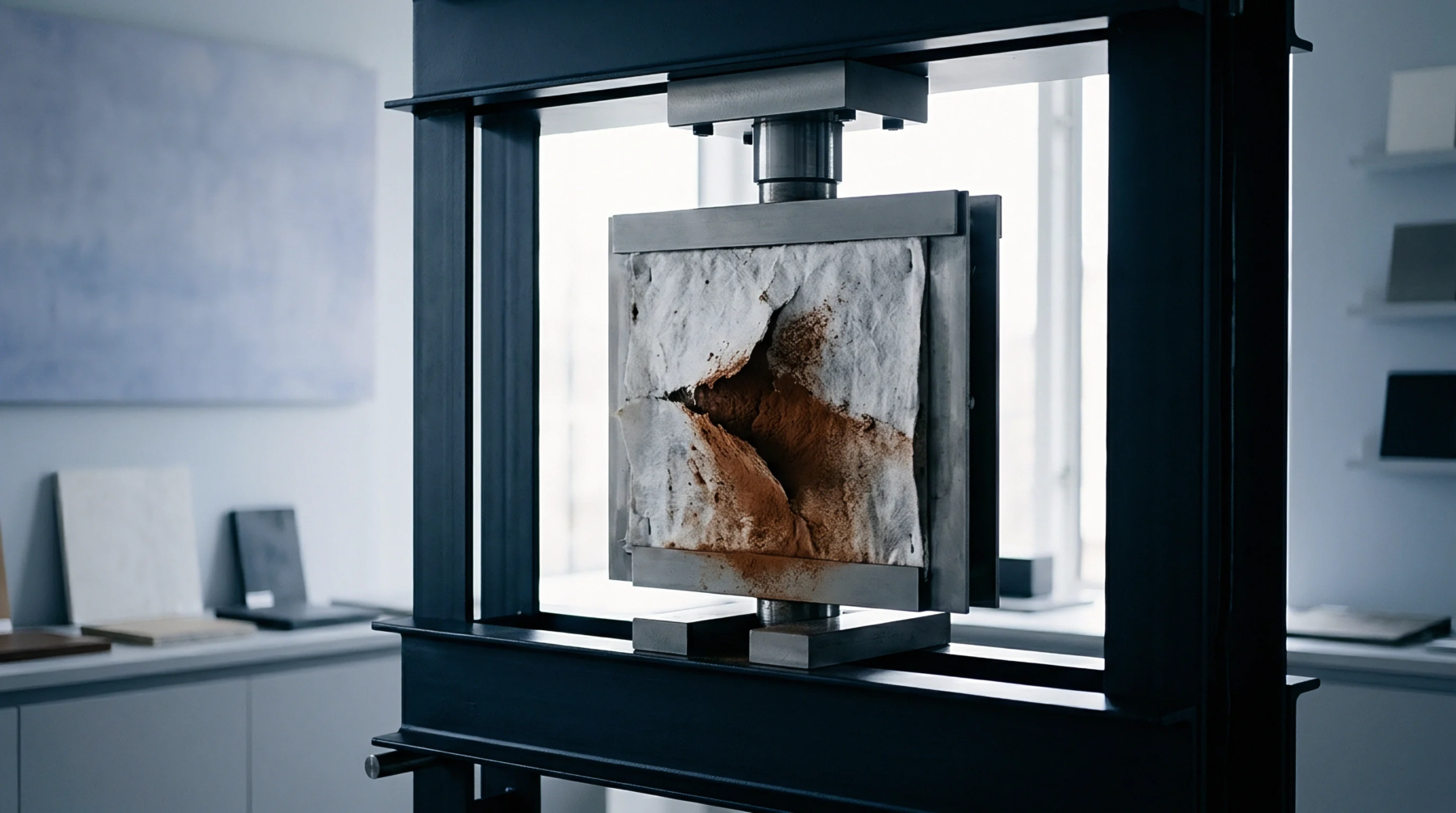
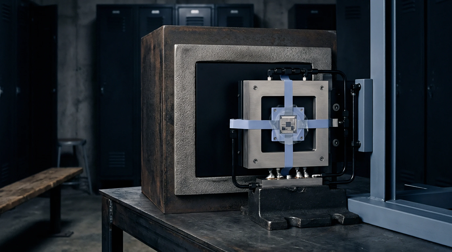
Thermal Spectroscopy
A measurement technique quantifies the viscoelastic properties of polymers by applying a periodic stress to a sample and recording the strain response to determine phase lag. Dynamic mechanical analysis isolates the storage modulus and loss modulus by detecting the timing difference between the deformation wave and the input force. This procedure operates within a controlled temperature or frequency sweep to generate a fingerprint of the material molecular mobility and structure.
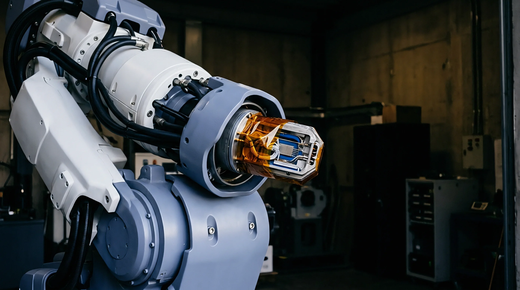
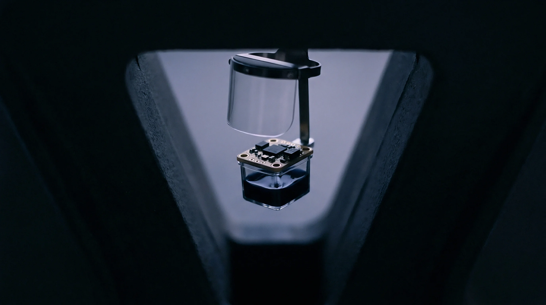
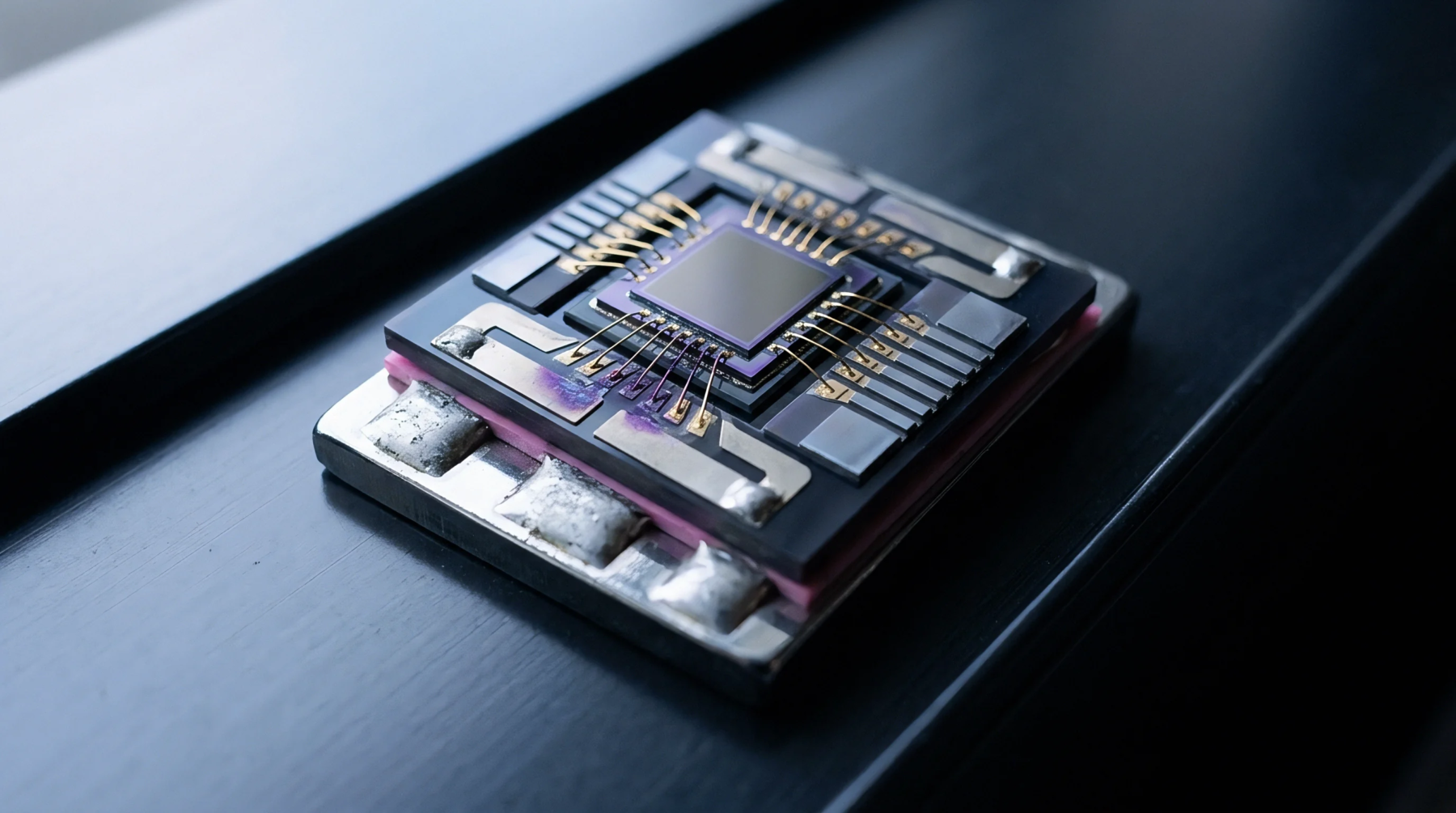
Analysts use these profiles to predict how plastics or elastomers perform under load because the phase difference provides data on energy dissipation. The instrument consists of a sample clamp, a drive motor, and a high sensitivity position sensor. A force transducer applies the oscillation, while the displacement probe monitors the result at the opposite end.
Digital signal processors convert the analog output into complex modulus values that characterize the damping capacity of a specimen.
Frequency Calibration
Mechanical testers compare recorded displacement against certified reference materials with known stiffness values to ensure validity. Periodic verification confirms that the motor output aligns with the force transducer input across the entire operational range. Drift often appears in the drive motor as friction increases or lubrication breaks down over extended test cycles.
Operators verify the phase angle accuracy by measuring a metal reed with negligible damping characteristics. Any deviation from the theoretical zero phase shift indicates a need for electronic recalibration or mechanical adjustment of the sample clamps. High humidity conditions within the laboratory environment introduce interference by changing the friction properties of the air bearings.
Standards set the allowable tolerance for these readings, which the manufacturer confirms during the qualification phase.
Sample Geometry
Precise preparation remains the limiting factor for obtaining reproducible modulus data during measurement. Dimensions must remain uniform along the entire length of the specimen to prevent stress concentration or irregular strain distribution. Analysts cut materials into strips or cylinders depending on the deformation mode required for the specific material class.
Surface irregularities cause the force to distribute unevenly, which generates a non-linear signal and inflates the measured damping factor. The mounting force inside the jaws also contributes to errors if the clamp pressure fluctuates during the temperature ramp. Thermal expansion of the fixture itself imposes a bias on the measurement, so the system subtracts the background compliance from the total signal.
Modulus Precision
Variations in the heating rate alter the peak tan delta position because the relaxation processes depend on thermal equilibrium within the bulk material. Consistent thermal conductivity across the sample thickness ensures that the sensor output accurately tracks the interior structural transition rather than surface temperature alone. Proper integration of the sensor output and the thermal control loop produces a signal with high repeatability.
Changes in the baseline noise floor happen when the drive motor encounters excessive stiffness or soft damping regimes. Valid results rely on the alignment between the oscillation frequency and the internal molecular transition speeds of the analyte. Quantitative stiffness values depend on maintaining a constant sample geometry through the entire test sequence.