Expansion Imbalance
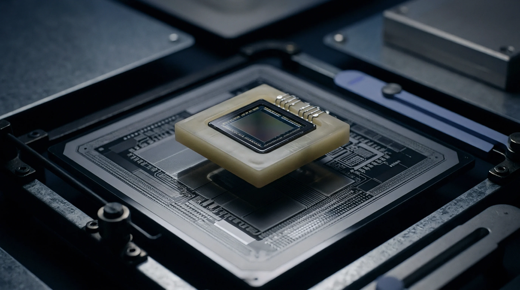
Internal tension grows when different materials joined together expand at different rates during a rise in local temperature. This thermomechanical stress measures the push and pull forces that act on bonded interfaces inside integrated circuits or circuit assemblies. It governs the structural stability of logic boards exposed to rapid cycling from winter storage to full operation at eighty degrees.
The phenomenon stops being defined if the material breaks apart entirely or undergoes a permanent shift in shape that resets the zero strain point. Metrologists use strain gauges or specialized digital correlation cameras to track the physical deformation that happens as components heat up. Precision at this level ensures that the materials chosen for the build can handle the intended lifetime of thermal movements.
Fatigue Mechanism
Cycle based loading occurs as every on and off event in the electronic device stretches and then relaxes the internal structure. When thermomechanical stress is high, it targets the interface where rigid silicon dies meet flexible plastic resin or composite boards. This mechanism creates microscopic fractures that grow into large cracks after hundreds of small shifts in the system heat level.
Consequence of these events includes lost signals or short circuits as internal conductive paths break or shift under the high load. Interference from mechanical vibration must be zeroed out during tests to ensure that every recorded strain relates purely to the thermal changes. Verification occurs in environmental chambers where researchers map the point of initial plastic failure under controlled ramp sequences.
Calibration Accuracy
Consistency in modeling these forces depends on the accuracy of the expansion coefficients recorded for the specific alloys and resins in use. The thermomechanical stress data provides the link between basic material science and the long term failure prediction models for high stakes hardware. Factors such as surface texture and the specific thickness of internal spacers shift the strain peaks found at the corners of high value items.
Drift in the measurement of these values happens if thermal sensors are not placed correctly near the primary high heat spots. Calibrating the test environment against ISO standards helps confirm that the observed movements result from true physical properties. Verification steps focus on repeating the test across twenty pieces to build a statistically valid target range for the design limits.
Structural Integrity
Documentation of fatigue life involves logging the number of cycles a joint survives before its electrical resistance shifts outside specified bounds. This thermomechanical stress signature provides proof that the assembly architecture can withstand the rigors of flight or high speed industrial use. Tolerance for variations in expansion is managed at the point of manufacture to maintain the integrity of the supply chain certifications.
Verification is checked during safety reviews to identify if a specific material mix is too rigid for the intended temperature range of the mission. This record keeping ensures that devices maintain their functional bonds for many years without cracking or lifting away from their target spots. Final acceptance depends on a clean report that shows the stress stayed within the geometric boundaries set in the engineering spec.