Residual Offset
An instrumentation signature maps the non-reproducible sensor output trajectory recorded during a full cycle of heating and subsequent cooling at a controlled rate within a closed system. The thermal hysteresis loop quantifies the divergence between ascending and descending temperature paths at an equivalent internal reference point. This variation emerges from internal structural stress, molecular reorganization delays, or mechanical expansion mismatch within sensitive electronic components during exposure to cyclical environmental shifts.
Manufacturers evaluate this deviation to determine the stability of absolute readings over repeated operation cycles. Drift during these cycles indicates the loss of sensor precision despite maintaining identical thermal states. Consistent cycles confirm the stability of material bonds inside the assembly.
Material Relaxation
Internal friction within the transducer body resists immediate response when temperatures change rapidly. The thermal hysteresis loop captures the lag between the applied stimulus and the conversion of physical expansion into an electrical signal. Discrepancies exist because the elastic deformation of the sensing element follows a different curve while the material regains its equilibrium state after cooling compared to the initial heating phase.
Engineers calculate this error by subtracting the output value at a fixed midpoint during cooling from the value detected at that same midpoint during the heating phase. Large areas inside the loop indicate structural fatigue or poor bonding between the sensing element and the substrate. Lowering the rate of temperature transition reduces the magnitude of this effect by allowing the internal structure time to achieve uniform equilibrium.
Calibration Drift
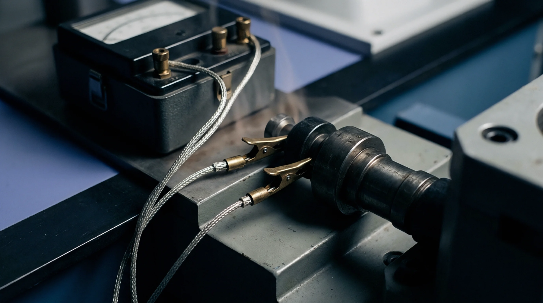
Metrological verification occurs by comparing the path of the thermal hysteresis loop against a certified reference probe within a climate chamber. Technicians record inputs at fixed intervals until the temperature range reaches its established limits. Standards set by industry bodies define the maximum acceptable gap in output voltage across the cycle.
Any point where the ascending and descending curves fail to converge represents a potential uncertainty in measurement. Field installations subject to rapid cycling endure higher risks of accumulation of these offsets compared to laboratory environments with stable temperatures. Verification of this parameter remains mandatory for high precision instrumentation used in aerospace or medical monitoring where accuracy holds consequences for equipment safety.
Signal Uncertainty
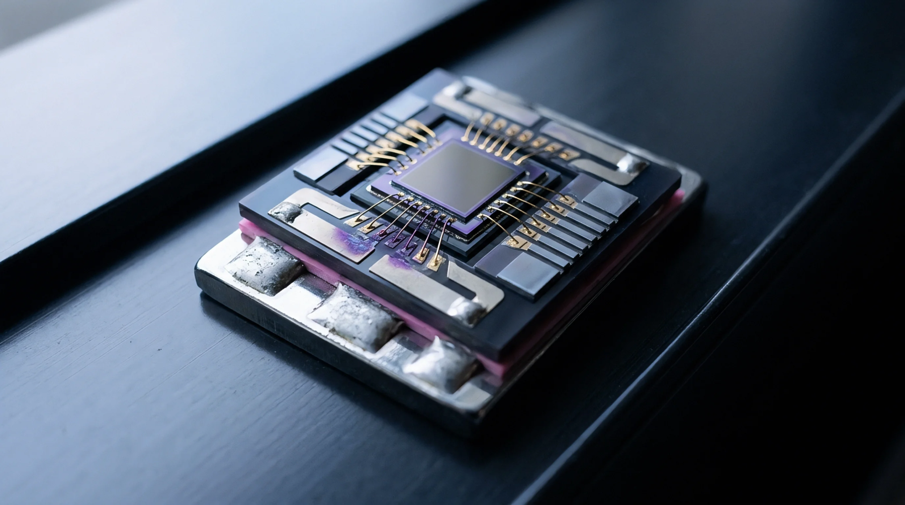
Sensor performance depends on the ability to minimize the influence of memory effects within the transducer assembly. A wide thermal hysteresis loop forces the integration of error bands into the final data interpretation to ensure the integrity of the measurement chain. Designers select materials with matched coefficients of expansion to prevent the mechanical tensions that generate such output patterns.
Reducing the thickness of the bond line between the sensor and the casing diminishes the path length for thermal transfer and helps the component reach temperature parity. Smaller loops facilitate tighter tolerances during the production phase and allow for more predictable corrections within the signal processing software. High levels of hysteresis indicate that the component requires replacement to maintain performance accuracy in demanding field applications.