Acoustic Imaging
High frequency acoustic wave propagation through solid interfaces allows non destructive inspection of internal structural integrity without requiring physical sectioning. Scanning acoustic microscopy operates by focusing high frequency ultrasound pulses through a coupling fluid onto a sample boundary, where acoustic impedance mismatches generate distinct echoes from internal discontinuities. Transducers operating between ten megahertz and two gigahertz convert these returning mechanical pressure waves into electrical radio frequency signals, mapping subsurface delamination, voids and microcracks with sub micron spatial resolution.
Transducer focal length determines the depth of field, while operating frequency sets the trade off between penetration depth and lateral resolution. Piezoelectric elements driven by short voltage spikes emit acoustic pulses, and the same element acts as a receiver during the quiet listening interval. Signal processing hardware digitizes the returning waveform amplitude and time of flight, translating raw voltage variations into a grey scale or false color acoustic micrograph that depicts hidden defects inside encapsulated components.
Wave Propagation
Acoustic impedance differentials dictate the fraction of wave energy reflected at any internal boundary, making density and longitudinal sound velocity the primary material properties governing contrast generation. Incident waves traveling through water encounter solid materials, and the ratio of acoustic impedances determines the reflection coefficient at that interface. Air gaps present nearly complete acoustic impedance mismatches, causing total reflection of the incoming sound beam and creating high contrast bright zones that reveal hidden delamination or cracking.
Epoxy resins, silicon dies and metallic lead frames exhibit characteristic acoustic velocities, allowing metrologists to identify material degradation or foreign inclusion by measuring signal phase inversion. High frequency attenuation rises sharply with frequency increase, limiting penetration depth in highly attenuating polymers and ceramics, so practitioners select lower frequencies to inspect thick assemblies despite the resulting loss in spatial lateral resolution.
Calibration Standard
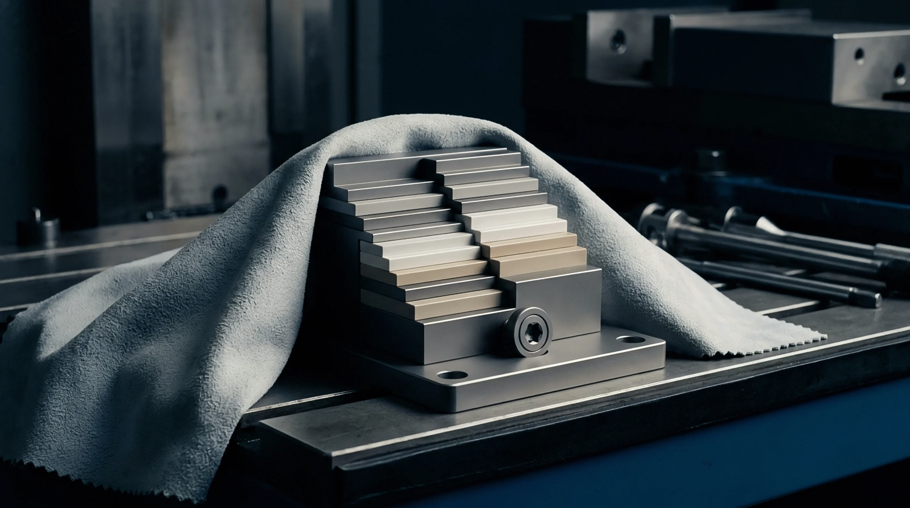
Metrological traceability relies on reference blocks containing known flat bottom holes or simulated delamination defects of certified dimensions, ensuring amplitude response repeatability across different testing sessions. Calibration procedures verify transducer focus, lateral scanning stage linearity and electronic gain stability by measuring baseline signal voltage from a polished quartz reflector placed at standard focal distance. Transducer beam profile distortion introduces measurement errors, so calibration routines map the acoustic field using a spherical target to quantify focal spot size and side lobe suppression.
Signal amplitude drift caused by thermal expansion in the mechanical scanning gantry or electronic component aging requires periodic verification against primary reference samples before production screening begins. Environmental temperature fluctuations alter acoustic velocity within the coupling water bath, shifting the focal plane relative to the sample surface and demanding real time acoustic velocity compensation based on measured bath temperature.
Resolution Limits
Diffraction physics dictates the ultimate lateral resolution boundary, restricting minimum detectable defect size to approximately half the acoustic wavelength in the propagation medium. High frequency sound waves yield finer spatial resolution but suffer from severe attenuation losses that restrict inspection depth within dense materials. Acoustic lens numerical aperture imposes another boundary, as highly focused beams provide superior lateral resolution at the cost of a shallow focal depth that struggles with warped or non planar samples.
Surface roughness on the entry face scatters the incoming acoustic beam, generating background noise that masks weak echoes from deep subsurface anomalies and degrades signal to noise ratios. Transducer bandwidth limitations restrict temporal resolution, preventing the separation of closely spaced reflections arising from thin adjacent internal layers within multi chip microelectronic packages. Acoustic impedance matching layers applied to the piezoelectric element face minimize internal reverberations, maximizing acoustic energy transfer into the coupling fluid and preserving the sharp pulse shape necessary for accurate time of flight depth profiling.