Resistance Shift
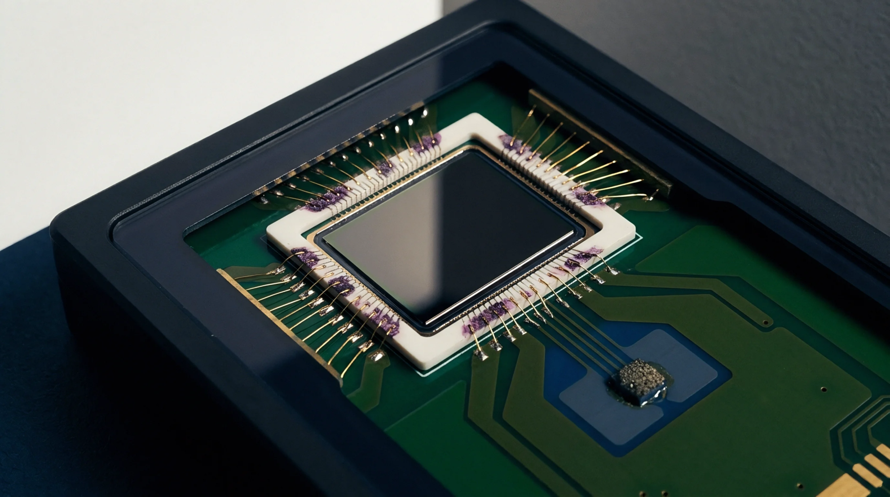
Strain measurement relies upon a specialized instrument converting mechanical deformation into electrical variation through semiconductor material properties. A piezoresistive transducer accomplishes this conversion by altering bulk resistivity under applied stress rather than changing geometric dimensions alone. Bulk semiconductor elements form the core sensing body where crystal lattice distortion shifts carrier mobility and consequently changes output resistance.
Silicon crystal orientation determines gauge factor magnitude, which dictates sensitivity performance across specific mechanical loads. Bridge circuit wiring translates small resistance shifts into measurable voltage differences under reference operating conditions. Thermal sensitivity gradients introduce measurement errors unless compensation resistors balance the bridge network across expected temperature ranges.
Overload boundaries limit maximum physical displacement before permanent crystal fracture occurs within the primary element. Calibration protocols establish initial offset values and linearity coefficients using deadweight testing equipment at standard laboratory temperatures. Signal conditioning electronics amplify low level voltage outputs while filtering high frequency electromagnetic interference picked up by connecting cables.
Field installations frequently experience zero drift caused by adhesive creep or mechanical hysteresis within mounting interfaces during prolonged cycling. Metrological verification requires periodic retesting against traceable standards to maintain specified accuracy classes inside industrial measurement loops.
Bridge Circuitry
Electrical balance across wheatstone configurations isolates resistive changes from extraneous environmental variables during operation. Constant voltage excitation supplies the bridge while differential amplifiers extract output signals proportional to applied mechanical strain. Power supply stability directly influences measurement resolution because voltage fluctuations alter output readings independently of physical deformation.
Resistor matching minimizes thermal zero shift by pairing elements with opposing temperature coefficients inside the sensing module. Shunt calibration resistors verify system gain without applying physical loads to the mechanical installation point. Wiring lead resistance introduces measurement errors in long cable runs unless four wire sensing configurations compensate for line losses.
Grounding shields eliminate common mode noise coupling into sensitive signal conditioning stages adjacent to the transducer body. Output linearity depends upon balanced bridge arm values across the entire operating range specified by the manufacturer. Signal impedance matching ensures maximum power transfer between sensing elements and subsequent data acquisition hardware.
Calibration Protocol
Metrological traceability demands rigorous verification procedures establishing measurement uncertainty limits under controlled environmental conditions. Reference standards apply known loads through mechanical fixtures while automated test systems record corresponding voltage outputs at multiple intervals. Nonlinearity corrections rely upon polynomial curve fitting algorithms programmed into digital signal processors following initial test runs.
Repeatability tests evaluate output consistency by cycling test loads repeatedly through identical operational sequences. Hysteresis errors appear as divergent output values between loading and unloading phases of verification routines. Temperature chambers subject the device to thermal extremes while logging zero output drift and sensitivity shifts simultaneously.
Calibration certificates document actual performance parameters against nominal design specifications at specific reference temperatures. Traceability chains connect local testing equipment directly to national metrology institutes through unbroken calibration hierarchies.
Installation Effects
Mechanical mounting practices dictate long term measurement stability by controlling stress distribution across the transducer interface. Adhesives secure bonded units to structural surfaces, and improper curing procedures cause premature debonding during thermal cycling. Torque specifications govern threaded installations to prevent housing distortion that induces parasitic strain readings on internal sensing elements.
Moisture ingress corrodes wire bonds and degrades insulation resistance between active circuits and grounded housings. Vibration isolation mountings protect sensitive sensing structures from high frequency mechanical shock loads encountered in heavy industrial environments. Thermal gradients across mounting brackets generate localized expansion forces that register as false mechanical strain signals.
Strain relief clamps prevent pulling forces on lead wires from transferring mechanical loads directly to the internal measurement cavity. Protective enclosures shield internal electronics from corrosive process fluids and explosive atmospheres present in chemical processing plants. Periodic inspection schedules identify mechanical degradation before catastrophic failure compromises measurement integrity across the operational network.