Quantifying Long Term Thermal Hysteresis Drift in High Density Process Transducer Deployments
Thermal hysteresis drift in high density transducer arrays stems from package microstructural strain relaxation and requires multi-cycle thermal preconditioning.


Creep
When piezoresistive pressure elements undergo thermal cycling, baseline offset displacement occurs as microstructural strain inside the package relaxes. In high-density mounting arrays, ambient temperature swings combine with heat generated by internal electronics to create thermomechanical stress cycles. Silicon sensor dies bonded to metallic headers expand at rates governed by their thermal expansion coefficients ~ silicon sits near 2.6 parts per million per kelvin, while stainless steel headers expand at rates exceeding 16 parts per million per kelvin.
Temperature ramps induce shear stress across the adhesive or metallic bond line joining the sensor element to its housing, causing silicon diaphragms to relax under thermal loading.
Thermomechanical stress within transducer assemblies dissipates through permanent microstructural rearrangements. Under cyclic stress, polycrystalline silicon strain gauges and internal metallization layers undergo localized dislocation slip. Over extended operational periods, glass frit seals and organic die-attach adhesives deform viscoelastically.
Because this inelastic behavior keeps the sensor structure from returning to its original geometry upon cooling, the resulting dimensional offset alters physical stress across the sensing diaphragm and shifts the uncompensated zero-pressure output signal.
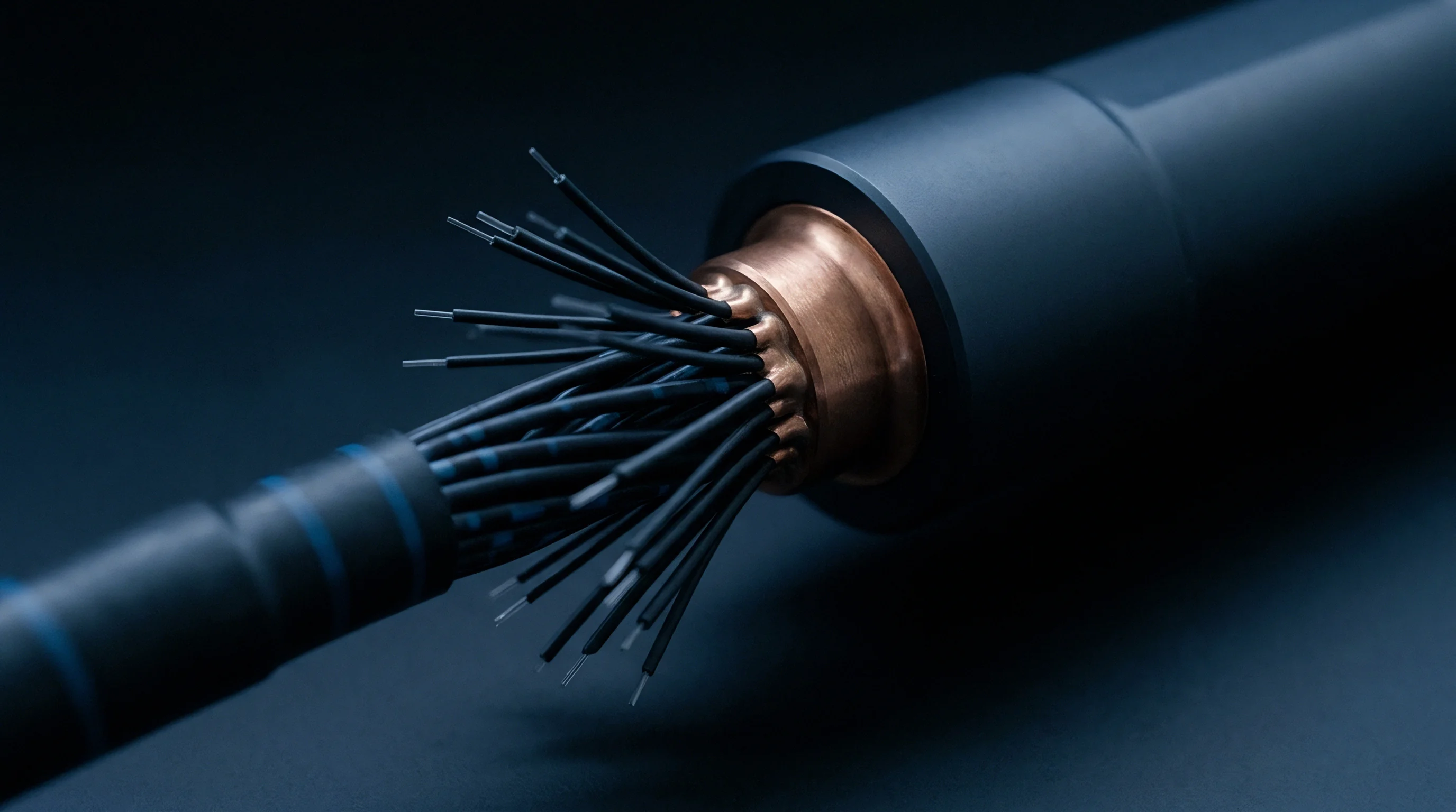
Structural Thermal Expansion Mismatch Mechanics
Silicon die attachment surfaces bonded to metallic header assemblies experience shear forces during temperature transitions. Header materials such as Kovar or 316L stainless steel, mismatched against monocrystalline silicon chips, set up a continuous strain field. Elevated process temperatures relax residual stresses introduced during high-temperature manufacturing steps like eutectic die bonding or high-temperature glass firing.
This relaxation shifts the zero-pressure baseline, creating an uncompensated output offset that remains permanent until subsequent thermal excursions induce further microstructural strain.
Transducers installed in dense process blocks undergo localized heating cycles that accelerate die bond relaxation. Repeated cycling between lower ambient limits and elevated process temperatures drives progressive creep in soft solder or organic adhesive layers. Over time, epoxies transition through localized glass transition zones, altering their elastic modulus and mechanical hysteresis.
Package stress ultimately dictates long term stability.
The primary packaging failure mechanisms driving long term thermal hysteresis drift include:
- Die Bond Viscoelasticity deformation occurs in polymer packaging materials subjected to continuous shear strain across thermal cycles.
- Header Metallization Dislocation movement shifts internal stress profiles in metallic sensor housings following repeated high-temperature exposure.
- Substrate Interfacial Delamination alters localized strain transfer between the piezoresistive element and the supporting mechanical structure.
- Glass Frit Microcracking releases built-in mechanical pre-loads required for stable low-pressure transducer baseline operation.

Adhesive Polymer Creep and Strain Relaxation
Epoxy compounds used for sensor mounting deform when exposed to elevated operating temperatures. Polymer chains slide past one another under internal structural strain, relieving pre-existing stresses while creating permanent geometric displacement. This molecular realignment alters the mechanical baseline transfer function of piezoresistive and capacitive sensing elements, and the loss of initial mechanical preload shows up as a persistent zero-point offset shift during post-exposure calibration checks.
Continuous thermal exposure in high-density installations accelerates polymer degradation mechanisms. Moisture entering adhesive interfaces promotes hydrolytic bond cleavage, reducing the shear modulus of structural bonds. A lower shear modulus decreases strain transfer efficiency from the sensing diaphragm to the internal transducer element, causing hysteresis error to accumulate across thermal excursions.
Thermal hysteresis manifests as a non-repeatable offset between ascending and descending temperature ramps.
Thermal cycling alters sensor baseline stability, though post-excursion zero offsets can also stem from external pipe strain rather than internal die bond relaxation.


Partition
Isolating permanent thermomechanical zero shifts from reversible thermal spans demands rigid test sequencing, as static calibration procedures fail to separate transient thermal shifts from permanent physical drift. Temperature coefficient errors are instantaneous, reversible changes in sensor output caused by temperature-dependent piezoresistive coefficients or amplifier gain shifts. Thermal hysteresis drift, by contrast, represents a permanent or semi-permanent baseline displacement dependent on thermal history and cycle direction.
Evaluating high-density process transducer arrays requires separating these error sources into independent uncertainty contributions.
Mathematically decomposing sensor error vectors requires multi-point thermal cycling across the full operating range. Reversible temperature effects follow predictable surface response equations, whereas hysteresis error displays path dependence and memory effects. Measuring transducer outputs at identical thermal equilibrium points during ascending and descending temperature ramps isolates the structural hysteresis loop; subtracting the reversible temperature coefficient model from raw output data then exposes the residual thermomechanical drift component.

Thermal Coefficient Separation Methods
Disentangling linear temperature shifts from structural hysteresis requires dual-ramp calibration profiles. Calibration systems ramp ambient temperature from minimum rated operational limits to maximum thresholds at controlled rates, incorporating dwell periods to ensure complete internal thermal equilibrium. Output measurements recorded at identical temperature setpoints during heating and cooling phases reveal residual mechanical hysteresis, with the difference between ascending and descending output values at any static temperature defining the thermal hysteresis margin.
Because static calibration fails to capture hysteresis, analyzing array data across successive cycles is necessary to separate initial stabilization shifts from long-term logarithmic decay. The initial thermal cycle typically generates the largest hysteresis loop due to the release of manufacturing pre-loads, while subsequent cycles produce smaller, highly repeatable loops until material degradation triggers accelerated drift.

Static Non Linearity and Hysteresis Decoupling
Polynomial curve fitting isolates higher-order sensor non-linearities from thermomechanical baseline shifts. Standard calibration routines fit third-order polynomials to transducer output data recorded at room temperature. Applying these static polynomials to data gathered across thermal ramps separates temperature-induced non-linearities from pure hysteresis offsets, and the residual error unaccounted for by temperature-compensated calibration matrices directly quantifies thermal hysteresis drift.
| Packaging Architecture | Diaphragm Material | Bonding Method | Thermal Expansion Mismatch (ppm/K) | Typical 1-Year Hysteresis Drift (% Span) |
|---|---|---|---|---|
Quantifying transducer stability across high-density banks requires systematic error budgeting. Metrologists combine expanded uncertainty terms from reference standards, environmental chamber gradients, and signal acquisition systems. Isolating sensor hysteresis from measurement system noise demands calibration rig stability three to five times higher than the target transducer specification limit.
A thin-film pressure sensor evaluated across a temperature excursion of 100 kelvin exhibits an uncompensated residual hysteresis shift of 0.08 percent of full scale span.
High-density process transducer arrays subjected to fluctuating process temperatures stabilize their hysteresis signatures after five continuous thermal cycles.


Array
Deploying high-density instrumentation banks introduces complex thermal coupling across adjacent transducer bodies. Compact cabinet layouts and crowded manifold blocks restrict airflow, creating localized heat build-up. Power dissipation from internal excitation circuits and signal conditioning electronics elevates transducer internal temperatures above ambient manifold levels, while adjacent sensors radiate thermal energy onto neighboring housings.
The resulting spatial temperature gradients across the process block distort process pressure readings.
Transducers operating in dense geometric configurations experience asymmetric thermal loading. Outer sensors lose heat to ambient cabinet air while center-mounted units sit in elevated microclimates. This thermal asymmetry causes non-uniform expansion across the manifold block, transmitting mechanical bending moments to individual pressure ports.
Structural strain from manifold distortion directly shifts sensor zero outputs, compounding internal packaging hysteresis drift.

How Do Mutual Heating Gradients Exacerbate Hysteresis?
Internal power dissipation within densely packed sensor enclosures creates localized temperature steps between adjacent units. Transducer excitation currents flowing through bridge circuits generate heat that must conduct out through the sensor body and process connection. When transducers are mounted on close center-line spacing, heat rejection paths become restricted, and elevated operational temperatures accelerate mechanical strain relaxation within internal seal polymers and die adhesives.
Mutual heating accelerates zero point wander, as array density directly correlates with elevated steady-state operating temperatures. A ten-transducer manifold block operating with 24-volt loop power can experience a 15-kelvin localized temperature rise over isolated baseline conditions. This elevated baseline shifts thermal cycling bounds higher, exposing internal materials to temperature zones where polymer viscoelastic creep occurs rapidly.

Microclimate Gradient Effects in Enclosed Racks
Stagnant ambient air within sealed DIN-rail housings establishes localized hot spots around power supply components. Temperature differentials between upper and lower housing sections induce variable hysteresis profiles across identical sensors installed in different rack positions: sensors located at the top of an enclosure experience higher continuous thermal stress than lower units, leading to divergent long-term drift trajectories across a single process monitoring array.
Thermal management in high-density installations relies on natural or forced convection patterns that vary spatially. Airflow blockage caused by dense wiring harnesses leads to stagnant boundary layers around specific transducer bodies, slowing down thermal dissipation during process warm-up and cool-down cycles and extending the time sensors spend within high-hysteresis thermal transition regions.
Uncontrolled thermal microclimates within dense sensor banks induce differential baseline wandering that corrupts multi-channel process differential pressure calculations.


Screening
Thermal preconditioning routines force early microstructural relaxation prior to field installation. Laboratory screening programs subject newly manufactured process transducers to controlled thermal cycling to accelerate initial non-linear hysteresis decay. Exposing transducers to temperature extremes outside standard operational ranges stabilizes adhesive bonds and glass frit seals before initial calibration runs, reducing early operational zero drift and producing predictable long-term performance.
Characterizing high-density transducer lots involves representative sample testing under simulated process stress. Calibration technicians use automated environmental chambers equipped with high-precision pressure controllers and traceable reference standards. The screening sequence records baseline sensor outputs across multiple thermal cycles to verify compliance with specified thermal hysteresis limits; units displaying expanding hysteresis loops across successive cycles indicate structural packaging defects and face batch rejection.

Laboratory Soak Cycle Construction
Environmental chamber programs designed for sensor stability testing specify dwell times based on packaging mass. Chamber air velocity must maintain rapid thermal transfer to achieve target transducer surface temperatures without introducing steep internal thermal gradients during ramp phases. Soak periods ensure complete thermal equilibrium across die bonds, sensor elements, and electronics assemblies ~ incomplete soak periods introduce artificial hysteresis artifacts into test datasets by misaligning internal component temperatures during output sampling.
Burn-in cycles reduce initial drift rates, with soak schedules for high-precision transducers specifying minimum dwell times of two hours at extreme temperature limits while data acquisition systems record transducer outputs continuously during dwell phases to detect isothermal strain relaxation. Pressure transducers showing output drift during static temperature soak phases demonstrate ongoing internal stress relaxation, signaling unsuitability for tight-tolerance process applications.

Accelerated Thermal Conditioning Regimes
Elevated temperature excursions shorten the time required to stabilize internal packaging stresses. Accelerated conditioning regimes increase thermal ramp rates and extend high-temperature soak limits within material design thresholds, forcing rapid polymer curing and strain relief in die attach interfaces. Screening protocols must validate that thermal ramp rates avoid inducing thermal shock defects such as substrate cracking or bond wire necking.
| Test Parameter | Standard Screening (IEC 60068-2-14 Nb) | Accelerated Stress Conditioning | High-Density Array Qualification |
|---|---|---|---|
Quantifying thermal hysteresis requires precise laboratory execution. The following procedure isolates long term hysteresis performance during batch acceptance screening:
- Mount transducers on a rigid, thermally mass-balanced aluminum calibration manifold inside the environmental test chamber.
- Connect transducers to automated pressure generation systems and multi-channel data acquisition instruments using low-noise cabling.
- Stabilize the test chamber at nominal reference ambient temperature (23 °C ± 2 °C) for a minimum of two hours.
- Apply zero and full-scale pressure calibration points to establish baseline output spans prior to thermal stress exposure.
- Execute ten continuous thermal cycles between specified minimum and maximum operational temperature bounds at a controlled ramp rate of 2 kelvin per minute.
- Record output signals at zero pressure and full-scale pressure at 10-kelvin increments during both ascending and descending temperature legs.
- Calculate hysteresis drift values by taking the maximum output difference between ascending and descending legs at matching temperature setpoints.
Compliance with IEC 60068-2-14 test schedule NB dictates continuous monitoring of output shift across ten consecutive thermal cycles.
Purchase specifications referencing ISO 10012 Clause 7.2 compel suppliers to furnish traceable multi-cycle thermal hysteresis verification certificates for each production lot delivered for high-density plant installation.


Drift
Time-dependent output instability follows a decay trajectory governed by internal material relaxation kinetics. Long-term thermal hysteresis drift in process transducers scales logarithmically with operational exposure time and cycle frequency: initial thermal cycles introduce substantial structural baseline shifts, followed by a declining rate of permanent deformation over subsequent months. Mathematically modeling this decay trajectory permits process metrologists to project calibration stability across multi-year operational cycles.
Long term stability models separate pure temporal aging from cycle-dependent thermal hysteresis accumulation. Temporal aging occurs continuously regardless of temperature variations, driven by baseline material oxidation, dopant diffusion, and structural outgassing, whereas cycle-dependent thermal hysteresis accumulates strictly during thermal excursions. High-density transducer installations experience both mechanisms concurrently, requiring logarithmic mathematical models to decouple time-based drift from cycle-based hysteresis offsets.

Logarithmic Aging Equations and Coefficients
Mathematical models describing long term baseline shift use logarithmic decay terms to represent strain relief. The total offset shift at operational time t equals the sum of initial manufacturing offset, logarithmic temporal aging, and cumulative thermal cycle hysteresis. Empirical parameters extracted from short-term laboratory thermal cycling tests provide the basis for calculating long-term drift coefficients, and fitting experimental transducer data to non-linear relaxation curves establishes operational stability bounds.
Uncertainty budgets require explicit hysteresis allowances. Calculating combined operational uncertainty requires integrating time-dependent hysteresis growth functions into standard static accuracy budgets. Because the continuous degradation of zero stability expands the overall measurement uncertainty band over time, operational drift models predict the precise month when cumulative transducer uncertainty exceeds process control limits, triggering scheduled recalibration intervention.

Extrapolation Risk in Multi Year Projections
Extrapolating short-term laboratory data across operational horizons introduces uncertainty margins, as material relaxation mechanisms that dominate early operational phases give way to secondary aging mechanisms over extended periods. Polymeric die bonds undergo slow chemical degradation under continuous thermal exposure, altering their mechanical stiffness properties after years of service. Linear or simple logarithmic projections fail to predict late-life drift acceleration caused by chemical bond degradation.
Thermal tolerance limits must be specified tightly, and reliability engineers must validate mathematical drift projections against field return data and periodic calibration audits. Incorporating confidence bands around empirical logarithmic decay curves accounts for statistical variance within component manufacturing lots. High-density deployments display broader drift distributions than isolated single-sensor installations due to variable internal microclimates across the array structure.
| Transducer Sensing Mechanism | Logarithmic Aging Coefficient (alpha) | Thermal Cycle Hysteresis Exponent (beta) | 3-Year Projected Zero Drift (% FS) | Upper 95% Confidence Limit (% FS) |
|---|---|---|---|---|
Long-term hysteresis prediction relies on accurate characterization of early-life relaxation kinetics under controlled environmental conditions.
Long term hysteresis stabilization occurs primarily during the initial thermal cycles following sensor packaging.
Determining whether sub-ambient thermal cycling permanently resets microstructural lattice strain in piezoresistive elements remains an open inquiry in process metrology.


Governance
Commercial specifications for process instrumentation omit thermal hysteresis tolerances from standard accuracy definitions. Datasheet accuracy statements typically group non-linearity, static hysteresis, and repeatability into a combined room-temperature tolerance figure, ignoring long-term baseline shifts induced by field thermal cycling. Buyers specifying transducers for high-density installations must mandate explicit thermal hysteresis drift limits within procurement documentation to avoid early operational failure.
Unverified hysteresis claims expose plant operations to unbudgeted maintenance costs. Process transducers that drift beyond control thresholds mandate frequent off-line laboratory recalibrations, increasing operational labor costs and plant downtime. Incorporating verified thermal hysteresis performance metrics into vendor selection matrixes establishes clear commercial accountability: suppliers offering lower purchase prices often utilize unconditioned, low-cost organic packaging adhesives that exhibit severe thermal hysteresis drift in high-density service.

Recalibration Economics and Drift Allowances
Establishing maintenance intervals for process instrumentation requires balancing recalibration labor against tolerance violation risks. Transducers displaying low thermal hysteresis drift permit extension of calibration intervals from 12 months to 36 months, reducing lifecycle maintenance expenditures. High-density process arrays containing hundreds of pressure loops compound these savings, justifying higher initial procurement costs for thermally stable transducer architectures.
Recalibration intervals depend on thermal exposure, making regular review of calibration test reports essential. Specifying high-stability transducers reduces overall cost of ownership despite premium initial unit purchase pricing. Procurement teams must evaluate total cost of ownership models incorporating field calibration costs, spare parts inventory, and process outage risks associated with sensor drift.
| Transducer Grade | Initial Unit Cost | Annual Hysteresis Drift Limit | Required Recalibration Interval | 5-Year Total Cost of Ownership |
|---|---|---|---|---|

Sourcing Contract Specifications for Dense Deployments
Procurement documents written for dense transducer installations specify explicit thermal hysteresis testing protocols. Sourcing contracts must mandate batch testing documentation detailing thermal cycle limits, ramp rates, and maximum allowable baseline drift. Including formal rejection clauses for delivered lots failing laboratory thermal preconditioning checks transfers technical compliance risks back to the device manufacturer.
Procurement teams managing high-density transducer deployments utilize the following verification checklist during vendor qualification:
- Traceable Thermal Certificates confirm vendor compliance with multi-ramp thermal hysteresis testing standards.
- Packaging Material Audits identify low-cost organic adhesive usage in high-temperature internal sensor interfaces.
- Batch Acceptance Testing verifies sample lot stability under accelerated thermal preconditioning regimes prior to shipment approval.
- Warranty Coverage Clauses explicitly extend baseline drift guarantees across the full operational temperature envelope.
Structuring technical specifications with explicit thermal hysteresis bounds ensures long-term process measurement integrity across high-density transducer installations.