Analytical Die Stress Modeling and Hysteresis Compensation in MEMS Sensors
Analytical die stress modeling isolates mechanical package strain from sensor signals while hysteresis compensation algorithms eliminate viscoelastic offset drift.


Bond
Package encapsulation and die attach media introduce mechanical coupling between external circuit boards and silicon sensing elements. When an encapsulated MEMS sensor experiences ambient temperature swings or structural flexing, mechanical forces travel directly through the leadframe and adhesive substrate into the silicon lattice. Silicon exhibits high mechanical stiffness.
The piezoresistive and capacitive structures microfabricated into the upper die surface respond directly to this localized strain, altering electrical zero offsets and scale factors independently of the measured physical quantity.
Thermal expansion mismatches form the primary baseline for permanent packaging stress. Single-crystal silicon carries a linear coefficient of thermal expansion near 2.6 ppm per degree Celsius at room temperature. Common organic substrate materials, such as FR-4 glass-epoxy laminates, present thermal expansion coefficients ranging from 14 to 18 ppm per degree Celsius.
Standard copper alloy leadframes expand at approximately 16.5 ppm per degree Celsius. When die attachment adhesives cure at elevated process temperatures, typically between 120 °C and 175 °C, the mechanical assembly locks into a stress-free equilibrium state only at that elevated curing point. As the assembly cools to ambient operational ranges, the differential contraction forces the thin silicon die into a concave bending state, imparting compressive surface stresses that easily exceed 100 MPa.
A die attach thickness below 15 micrometers elevates transferred packaging strain by 40 percent under minus 40 °C thermal soak.
Substrate forces distort sensor elements. Mechanical strain alters the atomic band structure of doped silicon, shifting carrier mobility along defined crystallographic axes. Piezoresistive pressure sensors rely on p-type diffusion resistors oriented along the 110 directions of a 100 silicon plane.
Compressive stress generated by packaging contraction decreases or increases piezoresistive values depending on longitudinal and transverse stress vectors. In capacitive accelerometer or gyroscope diaphragms, frame distortion warps the fixed anchor points, altering baseline gap distances and introducing parasitic tilt that degrades axis isolation.

Die Attach Mechanics and Thermal Mismatch
Silicone, epoxy, and eutectic die attachment layers possess distinct coefficients of thermal expansion relative to single-crystal silicon. Polymeric die attach adhesives reduce stress transmission through low elastic moduli, but introduce time-dependent viscoelastic creep. Eutectic gold-tin solder bonds supply hermetic stability and zero long-term creep, yet transfer nearly 100 percent of leadframe thermal expansion mismatch directly into the die base.
The mechanical behavior of the adhesive interface governs how ambient mechanical energy converts into active sensor offset drift.
Adhesive bondline thickness uniformity dictates stress field symmetry across the active sensing diaphragm. A non-uniform die attach layer causes asymmetric bending moments under thermal variation. When die attach fillet height varies across die corners, tilting moments induce localized shear stress gradients across embedded resistor bridges.
Shear loads shift offset voltages. The resulting output shift imitates an applied pressure signal, creating baseline offset errors that cannot be separated from real physical measurands using simple scalar temperature compensation.
- Direct leadframe shear transmission occurs when solder or glass-frit die attach layers transfer substrate thermal contraction straight into the lower silicon die surface without mechanical damping.
- Polymer gel stiffness modification develops during long-term thermal aging as soft silicone encapsulants undergo cross-linking, shifting their Young’s modulus from 1 MPa to over 10 MPa.
- Asymmetric fillet creep imbalance arises when uneven adhesive squeeze-out creates unequal lateral restraint along opposing die edges, producing twisting strain across sensitive flexure beams.
- Printed circuit board bending flexure propagates through structural solder joints directly into plastic-molded package bases, inducing low-frequency baseline noise under physical board vibration.

Piezoresistive and Capacitive Stress Coupling
Mechanical loads alter single-crystal lattice symmetry, shifting charge carrier mobility across integrated sensing bridges. In piezoresistive elements, the relative change in electrical resistance tracks localized stress components according to piezoresistive tensor matrix equations. Longitudinal stress components parallel to current flow modify resistivity through specific piezoresistive coefficients, while transverse stress components exert an opposing effect.
Unintended package stress generates stress differences across opposite arms of a Wheatstone bridge, producing zero-point shifts that drift with ambient thermal changes.
Capacitive sensing elements experience mechanical degradation primarily through geometry changes in microfabricated gap spaces. Differential package strain causes structural anchor pads to shift out of alignment. Fixed comb finger electrodes deflect relative to movable proof-mass fingers, altering baseline resting capacitance.
Thermal expansion creates residual strain. In surface-micromachined accelerometers, package-induced anchor displacement can shift cross-axis sensitivity from a nominal 1 percent up to 5 percent under extreme temperature boundaries, compromising multi-axis signal reconstruction.
Engineers who neglect multi-axial package stress distributions routinely produce sensor designs that pass ambient bench validation yet fail field thermal stability specifications. Unmodeled package strain forces post-assembly recalibration, drives higher field failure rates, and elevates total warranty costs during high-volume production deployments.


Laminate
Analytical formulations for internal silicon stress distributions demand planar elastic continuum models that account for multi-layer boundary conditions. A packaged MEMS die behaves as a composite laminated plate consisting of the circuit substrate, the adhesive die attach, the bulk silicon substrate, and surface passivation films. Calculating stress fields across this multi-layer structure requires solving partial differential equations governing plate deflection under thermal mismatch loads.
Classical plate theory assumes thin geometries and negligible transverse shear deformations. MEMS packaging geometries feature substrate thickness dimensions comparable to die length dimensions, invalidating pure Kirchhoff plate assumptions. Applying Timoshenko beam theory or Mindlin plate theory accounts for transverse shear flexibility within the relatively soft polymer adhesive layer.
The shear deformation of the adhesive layer absorbs a significant portion of the lateral displacement mismatch between the silicon die and the carrier substrate.
Calculations begin by defining force and moment equilibrium equations across the composite cross-section. Let subscript 1 represent the silicon die with thickness t1, Young’s modulus E1, and thermal expansion coefficient α1. Let subscript 2 represent the substrate layer with parameters t2, E2, and α2.
The die attach material forms an intermediate layer with thickness ta and shear modulus Ga. The governing differential equation for interface shear stress τ(x) along die length axis x, measured from die center x = 0 to die edge x = L, follows the classical Suhir formulation:
fracd2 τ(x)dx2 – k2 τ(x) = 0
The parameter k represents the compliance factor of the multi-layer assembly, defined through the mechanical properties of the constitutive layers:
k2 = fracGata left( frac1 – ν12E1 t1 + frac1 – ν22E2 t2 + frac3(t1 + t2)2E1 t13 + E2 t23 right)
Here, ν1 and ν2 represent Poisson’s ratios for silicon and substrate materials. Solving this differential equation with boundary conditions requiring zero axial force at die free edges x = ± L yields the spatial shear stress distribution:
τ(x) = fracΔ α · Δ Tκ · k fracsinh(kx)cosh(kL)
The parameter Δ α equals (α2 – α1), Δ T represents the temperature differential from die attach cure temperature, and κ represents interfacial compliance. Integrating interface shear stress along the die length provides the axial normal stress σ1(x) present within the silicon die surface:
σ1(x) = fracΔ α · Δ Tt1 left( frac1 – ν12E1 t1 + frac1 – ν22E2 t2 right) left( 1 – fraccosh(kx)cosh(kL) right)
Maximum normal compressive stress occurs precisely at the die center (x = 0), decaying to zero at the free die boundaries (x = ± L). The active MEMS diaphragm must sit in regions where spatial stress gradients remain minimal to suppress offset shifts.

Plate Theory and Multilayer Boundary Equations
Classical Mindlin and Timoshenko beam formulations describe cross-sectional shear deformation across composite stacks. Applying these mechanics to silicon dies bonded on alumina or organic substrates reveals that die curvature varies non-linearly with thickness ratios. Thinning a silicon die to reduce package height increases structural bending deflection under package strain.
Increased curvature amplifies surface-level strain on microfabricated sensing elements, increasing signal distortion.
Multi-layer analytical models incorporate passivation layers, metal traces, and silicon dioxide films present on the die surface. Compressively stressed oxide films grown at 1000 °C impart intrinsic wafer-level bow. When diced and mounted, combined intrinsic thin-film stresses and extrinsic packaging stresses produce complex biaxial stress states.
Analytical multi-layer formulations map these superimposed stress tensors directly into sensor output functions.
| Material Layer | Young’s Modulus (GPa) | Poisson’s Ratio | CTE (ppm/°C) | Shear Modulus (GPa) |
|---|---|---|---|---|
| Single-Crystal Silicon (100) | 130.0 | 0.28 | 2.6 | 79.6 |
| Alumina Substrate (96% Al2O3) | 300.0 | 0.21 | 6.5 | 124.0 |
| FR-4 Glass-Epoxy Laminate | 22.0 | 0.14 | 16.0 | 9.6 |
| Silver-Filled Epoxy Die Attach | 8.5 | 0.35 | 38.0 | 3.15 |
| Silicone Gel Encapsulant | 0.005 | 0.49 | 300.0 | 0.0017 |
| Eutectic Au80Sn20 Solder | 68.0 | 0.40 | 16.0 | 24.3 |

Anisotropic Stresses in Microfabricated Structures
Crystalline silicon exhibits elastic moduli that vary from 130 GPa along the 100 crystallographic direction to 169 GPa along the 110 orientation. Analytical stress transforms must apply transformed elastic stiffness tensor matrix elements Cij when converting volumetric mechanical strain into surface piezoresistive shifts. Piezoresistive coefficients π11, π12, and π44 depend heavily on doping concentrations and operating temperature.
Anisotropic mechanical properties cause square dies under isotropic package pressure to experience non-uniform strain fields along orthogonal axes. Stress fields concentrate at sharp die corners and interface step changes. Calculating piezoresistive bridge offset changes requires integrating localized stress tensors along the exact physical geometry of diffused or implanted resistors.
A fully closed-form analytical expression evaluates offset voltage Vout over bridge drive voltage Vin:
fracVoutVin = frac12 π44 left( σxx – σyy right)
Where σxx and σyy represent normal stress components along the orthogonal 110 axes of the piezoresistor bridge arms. Thermal variation modifies π44 with a negative temperature coefficient near minus 0.2 percent per degree Celsius. Modern analytical models couple temperature-dependent elastic moduli directly with temperature-dependent piezoresistive tensors, yielding closed-form multi-physics predictions of total zero-point shift.
Thick die attach layers with low shear moduli reduce transferred stress but increase die tilt risk during high-volume pick-and-place packaging.


Creep
Time-dependent strain relaxation in organic package interfaces creates severe long-term sensor drift during static mechanical loads. Polymeric adhesives, die attach epoxies, and plastic molding compounds exhibit viscoelastic deformation. Under constant packaging stress, polymer chains slide past one another, gradually shifting mechanical strain from the adhesive layer into the silicon substrate or relaxing initial packaging pre-loads over time.
This relaxation shifts baseline zero outputs over weeks or months, producing non-recoverable mechanical hysteresis.
Viscoelastic materials exhibit time-varying compliance described by generalized Maxwell or Kelvin-Voigt mechanical models. A Maxwell element models transient relaxation through a Hookean spring in series with a Newtonian dashpot. Applying constant strain ε0 produces an exponentially decaying stress response σ(t) over time t:
σ(t) = ε0 · E(t) = ε0 sumi=1N Ei e-fractτi
The term Ei represents elastic modulus contributions from distinct polymer chain relaxation modes, while τi represents associated relaxation time constants, defined as viscous damping ηi divided by modulus Ei. Polymeric die attach formulations contain multiple relaxation spectra spanning seconds to hundreds of hours. When a packaged sensor undergoes thermal shock, rapid expansion generates peak mechanical stresses that slowly dissipate as dashpot elements deform, creating time-dependent baseline drift at static holding temperatures.

Does Viscoelastic Relaxation Cause Dynamic Drift?
Polymeric adhesive matrices undergo molecular chain rearrangement under constant stress, producing an evolving strain profile over hundreds of hours. Dynamic temperature cycling accelerates viscoelastic movement by granting polymer chains thermal energy to overcome activation barriers. Operating near or above the glass transition temperature Tg drops polymer storage moduli by up to two orders of magnitude while increasing loss moduli, causing extreme creep rates and large baseline output hysteresis.
Polymer creep rates scale non-linearly with applied mechanical strain and temperature. Glass-transition transitions transform stiff, glassy epoxies into compliant, highly damping elastomeric states. When sensors undergo thermal profiling ramps from minus 40 °C to 125 °C, crossing Tg alters package boundary stiffness dynamically.
The path taken during heating differs mechanically from the path taken during cooling, generating open-loop thermal hysteresis loops in raw sensor output data.
Selecting low-viscoelasticity glass-frit or eutectic die attachment eliminates package-induced hysteresis across wide operating temperature bands.

Thermo-Mechanical Hysteresis Loops and Temperature Memory
Thermal cycling profiles induce non-reversible mechanical strain trajectories when heating rates exceed material relaxation time constants. Mechanical hysteresis manifests as a multi-valued output function where sensor readings at 25 °C differ depending on whether the temperature approached 25 °C from a cold baseline or a hot baseline. This temperature memory effect corrupts calibration parameters calculated from steady-state thermal characterization profiles.
Non-linear mechanical lag degrades bridge stability across operational life cycles. Glass-frit and metal solder bonds eliminate polymer relaxation but introduce micro-plastic yielding under high thermal stresses. Plastic deformation in eutectic solder layers creates permanent baseline offsets following severe thermal excursions.
Polymeric adhesives avoid plastic yield but exacerbate viscoelastic hysteresis. Supplier datasheets frequently state that zero-point offset stability holds within 0.1 percent across operating limits, omitting the qualification that thermal ramp rates above 5 °C per minute trigger transient packaging creep loops that double baseline shift error.
Packaging suppliers frequently explain baseline offset shifts after thermal exposure as normal stress relief, asserting that die attach materials stabilize fully after initial thermal seasoning cycles.


Inversion
Dynamic correction algorithms eliminate mechanical memory errors by calculating the mathematical dual of physical strain loops. Traditional linear or polynomial matrix calibrations compensate for static, single-valued thermal offset variations, but fail completely when sensor output depends on historical strain trajectories. Mathematical inversion models track stress history using history-dependent operators, calculating exact counter-adjustments in real time within embedded sensor microcontrollers.
The classical Preisach model represents hysteretic phenomena through an infinite ensemble of non-ideal relay operators γαβ. Each elementary relay accepts an input continuous signal x(t), such as sensor die temperature or raw bridge output, and outputs a binary state switching between plus 1 and minus 1. Switching thresholds depend on discrete parameter pairs α and β, where α ge β.
Threshold α dictates the up-switching point, while threshold β defines the down-switching value.
The continuous Preisach system output y(t) integrates these elementary operators weighted by a continuous density distribution function μ(α,β), known as the Preisach weight function:
y(t) = mathcalP = iintα ge β μ(α, β) γαβ , dα , dβ
The boundary separating active relay states in the (α, β) parameter plane forms a memory curve L(t) that shifts dynamically with input signal peaks and troughs. To compensate for package hysteresis, compensation firmware computes the mathematical inverse operator mathcalP-1. Applying inverse Preisach mappings directly to raw output readings Sraw(t) cancels hysteretic distortion, yielding true physical strain values Strue(t) = mathcalP-1.
Prandtl-Ishlinskii models present an alternative mathematical structure optimized for computationally constrained embedded microcontrollers. Instead of discrete relay operators, Prandtl-Ishlinskii formulations utilize continuous play operators Fr (t) parameterized by threshold radius r. The play operator equation models a mechanical backlash element with deadband width 2r:
y(t) = Fr (t) = max left x(t) – r, , min left x(t) + r, , y(t – Δ t) right right
Superimposing weighted play operators across a spectrum of threshold radii ri builds a continuous hysteresis model:
y(t) = w0 x(t) + sumi=1M wi Fri (t)
Where w0 and wi represent scalar weighting coefficients identified through bench characterization. The unique structural advantage of the Prandtl-Ishlinskii formulation lies in its analytical inversion property. The mathematical inverse of a Prandtl-Ishlinskii model with play operators is another Prandtl-Ishlinskii model containing modified threshold values ri’ and weights wi’ calculated via direct closed-form formulas:
ri’ = sumj=1i wj (ri – rj)
w1′ = frac1w0 (w0 + w1), quad wi’ = frac-wi(w0 + sumj=1i wj)(w0 + sumj=1i-1 wj)
This explicit analytical inversion eliminates iterative numerical solver loops, allowing low-power 16-bit or 32-bit automotive signal conditioning ASICs to perform inverse hysteresis compensation within microsecond clock cycles.

Operator Formulations for Non-Linear Memory Structures
Elementary play and stop operators aggregate weighted elementary hysteresis dead-bands to mirror complex hysteretic response curves. Selecting optimal threshold spacing for ri values dictates overall model fitting precision. Logarithmic threshold distributions allocate dense operator clusters near low-strain thresholds where polymer relaxation initiates, minimizing residual modeling errors below 0.05 percent full scale.
Model identification utilizes characterization data acquired during slow thermal ramps across sensor operating limits. Parameter identification algorithms employ non-linear least squares optimization to solve for weights wi. Memory space demands scale linearly with operator count M. Execution within embedded ASICs requires M memory storage locations to preserve internal operator states yi(t – Δ t) across power cycles, preserving historical mechanical state continuity.
| Hysteresis Model | Memory Depth | Analytical Inversion | Execution Overhead | ASIC Memory Footprint |
|---|---|---|---|---|
| Classical Preisach Model | Non-local memory | Numerical numerical mesh | High (2D integration) | Large (256+ state grid) |
| Prandtl-Ishlinskii Play | Local memory | Closed-form analytical | Low (Scalar additions) | Small (10-16 scalar weights) |
| Generalized Duhem Model | Differential state | Implicit differential | Moderate (ODE solver) | Medium (Derivative states) |
| Polynomial Lookup Table | Zero (Static mapping) | Direct table reverse | Ultra-low (Interpolation) | Medium (Static matrix points) |

Digital Signal Processing Implementations
Embedded firmware processes piezoresistive bridge signals through real-time lookup routines to eliminate mechanical strain distortion. Modern automotive pressure sensor signal chains execute digital hysteresis algorithms within dedicated digital signal processor blocks integrated inside the sensor interface ASIC. The signal processing chain executes compensation steps in strict sequential order to prevent transient memory corruption.
- Analog to digital signal conversion digitizes raw bridge output voltage and integrated temperature diode signals at 16-bit resolution with oversampling to suppress high-frequency thermal noise.
- Temperature signal linearization applies third-order polynomial corrections to raw temperature readings, generating accurate thermal inputs for dynamic hysteresis operator calculations.
- Play operator state updates evaluate current digitized temperature values against preserved internal operator threshold boundaries, updating state array variables in real time.
- Inverse operator matrix accumulation multiplies updated play operator states by inverse weighting coefficients wi’, summing terms to calculate exact baseline offset correction voltage.
- Primary signal extraction subtracts calculated offset correction voltages from raw digitized bridge values, yielding true stress-compensated pressure output data.
Compliance with AEC-Q103-002 automotive pressure sensor standards requires zero-point drift verification across 1,000 thermal shock cycles.
Consider a practical worked calculation for a piezoresistive pressure sensor die mounted on an organic substrate. Assume a die size of 2.0 mm by 2.0 mm by 0.3 mm with a nominal bridge resistance of 5.0 kΩ and longitudinal piezoresistive coefficient πL = 450 × 10-11 , Pa-1. Assume thermal cycling induces a residual biaxial package stress excursion Δ σ = 20 , MPa with an uncompensated baseline hysteresis loop width equal to 2.5 percent of full-scale span.
Without dynamic hysteresis modeling, this packaging strain introduces a 2.5 percent measurement error. Applying a 12-operator Prandtl-Ishlinskii inverse model reduces residual hysteretic offset shift to under 0.08 percent of full-scale span across a minus 40 °C to 125 °C operating range.
In accordance with ISO 26262 functional safety specifications, section 5.4.2 mandates that sensor microcontrollers verify the integrity of internal hysteresis state registers upon startup, triggering a diagnostic fault flag whenever calculated correction factors exceed upper physical plausibility limits.


Probe
Bench metrology systems isolate package strain contribution by combining controlled environmental profiling with high-precision optical or electrical monitoring. Characterizing analytical die stress models requires decoupled measurement setups capable of separating thermal zero shifts caused by piezoresistive temperature coefficients from zero shifts caused by thermo-mechanical packaging strain. Isolating these mechanisms demands multi-step environmental chamber characterization on unencapsulated dies alongside fully packaged assemblies.
Bench testing utilizes custom silicon test chips featuring integrated piezoresistive stress rosette sensors. A full four-element 0-45-90 degree stress rosette embedded directly adjacent to active MEMS flexure diaphragms measures in-plane stress tensor components σxx, σyy, and τxy in real time. Piezoresistive stress rosettes yield direct physical values for packaging stress profiles during adhesive curing, thermal shock profiles, and humidity preconditioning ramps.

Environmental Stress Profiling Protocols
Thermal chambers apply controlled soak ramps from minus 40 °C to 125 °C while digital multimeter arrays log bridge output voltages. Chamber ramp rates must hold at precise speeds, typically 1 °C per minute during steady-state parameter extraction and 10 °C per minute during transient viscoelastic characterization. Thermal soak times at temperature extremes extend to a minimum of 60 minutes, ensuring structural assembly components reach uniform thermal equilibrium.
Moisture absorption preconditioning elevates package strain through hygroscopic swelling of plastic encapsulation compounds. Polymer molding compounds absorb atmospheric moisture, expanding volumetric dimensions independently of temperature. Testing protocols execute JEDEC MSL-3 moisture sensitivity preconditioning, subjecting assemblies to 85 °C and 85 percent relative humidity for 168 hours prior to solder reflow simulation, mapping hygroscopic expansion stress back into the analytical die stress model.
Verification protocols follow a strict sequential execution sequence to extract exact material constants without introducing confounding environmental variables:
- Mount bare, unencapsulated piezoresistive test dies onto low-expansion invar carriers using non-stressing gel suspensions to establish intrinsic silicon temperature coefficients.
- Place unencapsulated assemblies into environmental test chambers and record baseline bridge resistance values across minus 40 °C to 125 °C thermal ramps at 10 °C increments.
- Assemble identical silicon test dies into target commercial packaging configurations using selected production die attach epoxies and plastic molding compounds.
- Subject fully encapsulated sensor packages to identical thermal ramps while continuously logging output voltage shifts from integrated stress rosettes.
- Subtract bare die baseline temperature coefficients from fully packaged sensor outputs to isolate absolute thermo-mechanical packaging stress curves.
- Perform time-dependent holding tests at 125 °C for 100 continuous hours to extract viscoelastic relaxation parameters and update Maxwell relaxation spectrum models.
Laser Interferometry and Strain Extraction
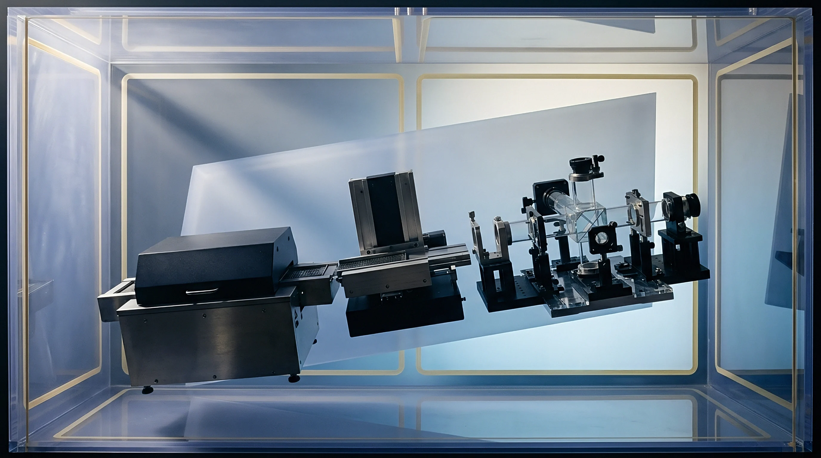
Coherent light displacement mapping resolves nanometer-scale surface deformation across bare silicon elements mounted on printed wiring boards. Digital holographic microscopy and electronic speckle pattern interferometry capture out-of-plane surface warpage profiles while packages undergo thermal cycling inside optical window chambers. Interferometric fringe pattern density directly reflects surface bending curvature, providing high-resolution experimental validation for analytical Mindlin multi-layer plate deflection models.
Double-sided interlocked strain gauges isolate true pressure signals from mechanical printed circuit board bending.
Optical displacement measurements correlate directly with electrical zero-point shifts recorded across Wheatstone bridge terminals. Comparing interferometric warpage maps against finite element stress models validates selected mechanical layer compliance constants. When optical warpage profiles indicate asymmetric die bow, sectioning and cross-sectional micro-imaging frequently reveal die attach voiding or inconsistent adhesive fillet heights along package edges.
What optical fringe resolution thresholds are required to distinguish between reversible elastic board bending and permanent viscoelastic die attach creep during high-g transient shock testing?

Yield
Wafer fabrication variations and assembly packaging tolerances dictate the final cost per calibrated unit in high-volume manufacturing. Small variations in wafer thinning processes, die attach dispense volumes, and molding compound cure cycles alter transferred stress levels across production lots. Uncontrolled packaging stress drives wide baseline offset distributions, requiring longer calibration times on automated test equipment and reducing total factory output yield.
Wafer grinding operations introduce residual subsurface damage that degrades mechanical silicon strength and alters surface piezoresistive response. Backside grinding processes utilize coarse diamond grit wheels to reduce wafer thickness from 750 micrometers down to 100 micrometers. Subsurface micro-cracks impart localized compressive residual stress fields spanning several micrometers into the silicon depth.
Chemical-mechanical polishing or chemical etching post-grinding removes damaged crystal layers, stabilizing mechanical baseline parameters and suppressing lot-to-lot offset variation.

Wafer-Level Stress Tolerances and Screening
Thin-film residual stresses across six-inch and eight-inch silicon wafers induce offset spreads before dicing and encapsulation. Silicon nitride passivation layers and aluminum metallization traces carry intrinsic tensile or compressive stresses depending on plasma-enhanced chemical vapor deposition temperature and gas flow ratios. Wafer bow measurements using laser deflection tools screen out wafer lots exceeding maximum structural curvature limits prior to assembly operations.
Wafer-level probe testing measures unencapsulated sensor bridge parameters, establishing baseline zero offsets prior to packaging. Advanced packaging facilities execute wafer-level stress compensation by trimming thin-film resistor networks using automated laser systems. Laser trimming compensates for intrinsic wafer stress, but cannot anticipate extrinsic stresses introduced later during die bonding and plastic molding encapsulation steps.

Commercial Sourcing and Multi-Foundry Allocation
Procurement specifications establish strict die-attach material lot consistency to prevent field failures from uncalibrated package strain. Changing die attach adhesive suppliers or shifting assembly lines to alternate packaging vendors alters material glass transition temperatures, thermal expansion coefficients, and viscoelastic relaxation spectra. A sensor design calibrated using dynamic hysteresis compensation tuned for an original adhesive formulation experiences severe offset drift if an alternate supplier material presents different relaxation time constants.
Second-sourcing strategies demand complete thermo-mechanical requalification. Sourcing practices must audit assembly vendor epoxy dispense systems, ensuring bondline thickness tolerances hold within plus or minus 3 micrometers across high-volume production runs. Inconsistent bondline thickness shifts Suhir interface shear compliance factors, rendering fixed firmware hysteresis compensation parameters ineffective across lot boundaries.
| Die Attach Formulation | Cure Schedule | Glass Transition Tg (°C) | Modulus @ 25 °C (GPa) | Relative Hysteresis Risk | Landed Cost Impact |
|---|---|---|---|---|---|
| Silver-Filled Conductive Epoxy | 150 °C / 60 min | 95 | 7.5 | High (Viscoelastic) | Baseline reference |
| Low-Stress Silicone Adhesive | 120 °C / 30 min | -50 | 0.005 | Low (Soft compliance) | +12 percent |
| Au80Sn20 Eutectic Preform | 310 °C / 2 min | N/A (Metallic) | 68.0 | Medium (Plastic yield) | +85 percent |
| Low-Temperature Glass Frit | 420 °C / 15 min | 380 | 60.0 | Zero (Brittle elastic) | +40 percent |
Selecting die attachment chemistry involves clear financial trade-offs between component cost, calibration test time, and field failure exposure. Low-cost organic epoxies minimize upfront bill-of-materials expenditure, but force extended environmental test chamber profiling to extract individual unit hysteresis parameters. High-cost compliant silicones or glass-frit bonds reduce packaging stress transmission, shortening factory test cycles and yielding predictable long-term zero-offset stability in demanding applications.