Interconnect Topology
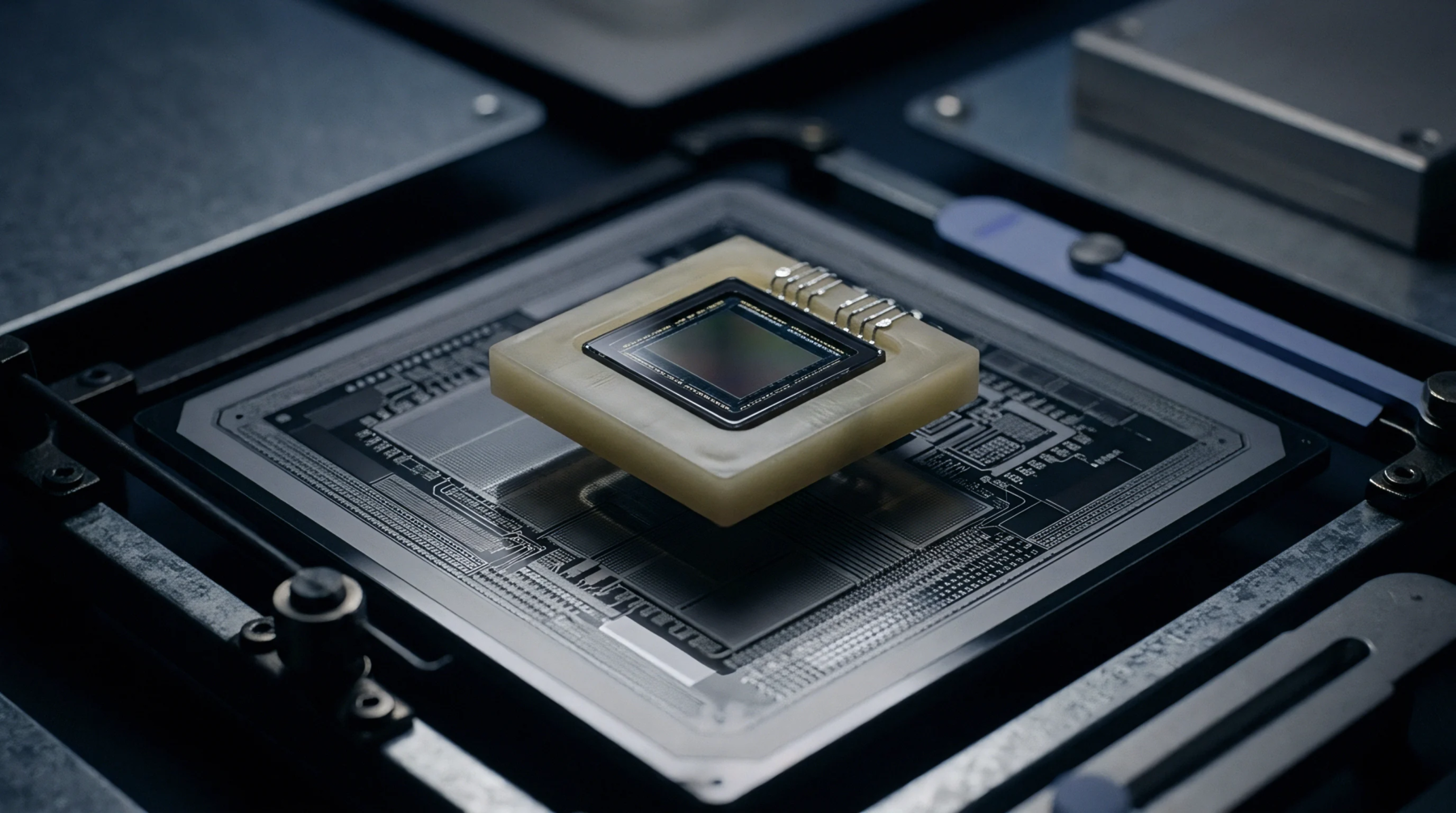
Functional interface structures within an integrated circuit package divert the electrical signals from the tight spacing of the silicon die to a wider footprint. The redistribution layer enables the use of standard printed circuit board tolerances for mounting advanced microchips.
Process Integration
Manufacturers deposit dielectric materials and conductive traces using lithographic techniques similar to those found in wafer fabrication. Creating a redistribution layer involves multiple steps of spinning and etching to build the necessary routing paths. This structure allows for the consolidation of multiple functions into a single package without increasing the total chip size.
Automated inspection tools verify the continuity of these traces before the final assembly steps. Precision in the alignment of these layers determines the overall yield of the packaging facility.
Electrical Performance
Shortening the distance between the die and the board helps to reduce parasitic inductance and resistance. A well-designed redistribution layer optimizes the power delivery and signal integrity for high-speed processors and memory modules. The choice of dielectric material impacts the capacitance of the traces, which affects the overall bandwidth of the system.
Package Reliability
Mechanical stresses arising from the mismatch in thermal expansion coefficients are often absorbed by the ductile metal in these layers. The redistribution layer protects the fragile silicon surface from the mechanical forces applied during the assembly and soldering process. It provides a flexible interface that enhances the durability of the final electronic product.