Physical Layer Signal Integrity Design for High Capacitance Sensor Networks
Active bus accelerators and differential transceivers preserve signal integrity across high-capacitance sensor lines by isolating slow capacitive RC edges.


Charge

Slew Degradation across Distributed Interconnects
Distributed capacitance along long sensor runs rounds off signal edges well before pulses arrive at receiver logic gates. Total capacitive loading builds from transceiver pin capacitance, PCB trace geometry, ESD diodes, and the intrinsic capacitance of the wiring harness. Open-drain architectures like standard I2C degrade rapidly once aggregated capacitance clears the nominal four-hundred picofarad specification limit.
Pull-up resistors return the line high along an RC exponential curve dictated by the pull-up value and lumped capacitance. As distance and tap counts increase, that exponential rise drags out into a shallow slope. Receiver input stages linger in the indeterminate switching band for excessive nanoseconds, leaving the line open to coupled noise and local ground bounce.
A distributed capacitive load of eighteen hundred picofarads expands a standard three-thousand ohm pull-up transition time beyond four microseconds, violating forty-four kilohertz timing constraints.
Low-side open-drain driver transistors introduce an asymmetric physical limit. Pulling down discharges the node briskly through a low-impedance channel, typically between ten and fifty ohms on modern silicon. Pulling back up to rail voltage relies entirely on passive pull-ups or active terminations.
Trimming pull-up resistance to sharpen rise times pushes the low-level output voltage upward: sinking twenty milliamperes through a standard four-milliammeter footprint driver drives the logic-low output past three-tenths of the supply rail, eroding noise margins against low-state ground transients. High-capacitance sensor buses therefore require strict decoupling between pull-up current injection and driver sink capabilities.

Capacitance Attribution in Multi-Sensor Assemblies
Lumped models break down when cables separate cluster nodes by more than three meters. Every element across the interconnect introduces dielectric displacement current that distorts edge transitions. Trace pairs on standard FR4 multilayers contribute roughly three picofarads per inch, whereas shielded twisted-pair industrial cable introduces between fifteen and thirty-five picofarads per foot.
An assembly of twenty environmental or industrial pressure sensors distributed across fifteen meters of shielded conduit routinely accumulates near four nanofarads of capacitive load.
| Interconnect Segment | Physical Contribution | Typical Loading Value | Tolerance Band |
|---|---|---|---|
| Sensor Package Pin and Die | Internal bondwire and electrostatic protection | 7.5 pF per node | ±2.0 pF |
| Printed Circuit Trace | Microstrip over solid ground plane | 3.2 pF per inch | ±0.4 pF |
| Shielded Twisted Harness | Polyethylene insulation jacket | 52.0 pF per meter | ±6.0 pF |
| TVS Diode Array | Transient voltage clamping silicon | 14.0 pF per line | ±3.5 pF |
| Terminal Header Block | Through-hole pin and socket receptacle | 2.8 pF per contact | ±0.5 pF |
Surface-mount transient suppression diodes add an underappreciated parasitic load. Standard clamping diodes routinely add fifteen picofarads each, an overhead that compounds quickly on multi-drop buses. Field packaging often places dual-rail TVS arrays across every tap point without accounting for cumulative capacitance.
Specifying ultra-low-capacitance diode arrays rated below zero point five picofarads protects edge rates across dense buses, though these components raise bill-of-materials costs up to four times over general-purpose silicon suppressors.
Adjusting pull-up resistance cannot offset cable capacitance once transit delays outrun edge rise times. Managing heavy capacitive loads requires active drive approaches rather than adjustments to passive pull-up resistors.


Buffer

Segmenting Loads via Active Accelerators and Repeaters
Isolating high-capacitance trunk cables from local branch drops prevents cumulative rise-time breakdown. Bus splitters, level-translating buffers, and rise-time accelerators break broad lumped topologies into isolated sub-domains. Bi-directional I2C buffers track direction using internal voltage offsets or current comparators.
An offset buffer maintains a forty to one hundred millivolt differential between its input and output logic-low levels, avoiding latch-up while delivering regenerated edges to down-stream sensor clusters.
Active pull-up circuits operate by sensing bus slew rates. Once the line crosses the low logic threshold with sufficient velocity, a switched internal source fires, injecting ten to thirty milliamperes into the interconnect for several dozen nanoseconds. The voltage climbs along a steep linear ramp instead of an exponential curve.
As the potential approaches ninety percent of the supply rail, the booster shuts down, letting a quiet static resistor hold the rail state without inducing thermal drift or ringing.

Differential Conversion for Industrial Cable Runs
Single-ended signals routed through three meters of industrial multi-conductor cable suffer frequent packet loss and timing violations from electromagnetic noise. Converting single-ended buses like I2C or SPI into balanced differential pairs using RS-485 or CAN physical transceivers resolves common-mode ground shifts. Differential lines terminate into matched loads, eliminating capacitive settling tails and swapping weak open-drain pull-ups for high-current push-pull stages that can drive thirty meters of twisted pair at five hundred kilobits per second.
Push-pull differential physical layers transform distributed wire capacitance into controlled transmission line impedance terminated by discrete matching resistors.
Differential conversion requires transceivers, local supplies, and termination networks at every drop. System architecture dictates whether bridges sit directly behind individual sensors or gather multiple drops onto an aggregator board. Installing a compact bridge transceiver inside an overmolded cable head minimizes parasitic stub length at the connector, preserving line balance along the main high-voltage harness.

Why Do Bus Buffers Mask Ringing Anomalies?
Repeaters isolate signal reflections by decoupling driver impedance from down-stream cable boundaries. When an unbuffered edge encounters an open stub, the reflection returns toward the host driver, appearing on an oscilloscope as an under-damped oscillation or plateau. The buffer receiver terminates that reflection, showing a static capacitive load to the upstream controller while launching a clean step down the secondary line.
This edge regeneration masks transmission line mismatches that would otherwise cause parity errors on unbuffered buses.
- Host transmission starts when the microcontroller pulls the primary bus low, sinking current through its local internal driver stage.
- Threshold sensing triggers as the voltage crosses the buffer internal comparator level, activating the secondary pull-down circuit.
- Secondary line discharge proceeds via an integrated low-side field-effect transistor designed to sink thirty milliamperes without thermal runaway.
- Release and rise acceleration engages when the master releases the bus, turning on internal current booster circuits to overcome branch capacitance.
Powering isolated nodes introduces ground loop risks. Ground differentials between remote machinery drive circulating currents through cable shields or reference wires, shifting local switching thresholds. Without galvanic isolation, common-mode offsets readily exceed the maximum ratings of low-voltage sensor silicon.
Placing digital isolators alongside bus buffers stops circulating ground currents and shields host logic from destructive plant-floor transients.
Inadequate power decoupling at the buffer leads to bus lockups, corrupted acknowledge bits, and dropped readings during concurrent sensor read cycles.

Drop

Physical Tap Topology and Stub Reflection
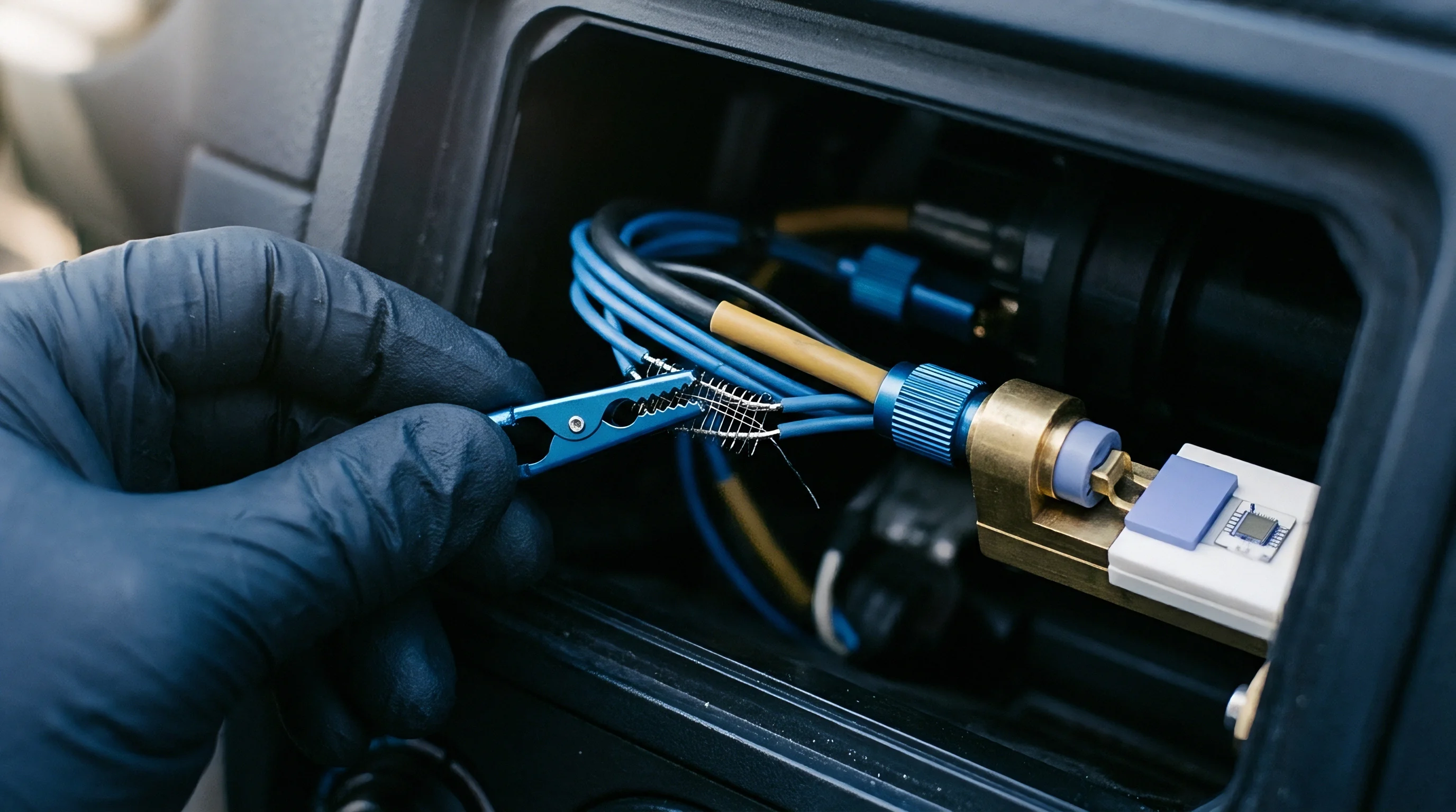
Harness geometry dictates where transmission line discontinuities occur. Splices, terminal blocks, and connector drops act as capacitive stubs branching off the main line, each introducing trace capacitance and pin inductance that create local impedance dips. When a fast edge hits a low-impedance tap, it reflects a negative pulse back to the transmitter, forming a shelf in the rising waveform.
Where that notch coincides with sensor receiver thresholds, logic blocks register false clock cycles.
Restricting tap length minimizes reflection energy. Sensor stubs must stay under one-tenth of the edge transition electrical length to behave as lumped capacitive loads instead of transmission lines. For a driver with a twenty-nanosecond fall time, the electrical length through PVC insulation is roughly four meters, meaning stubs over forty centimeters require termination or slew filtering to avoid errors.
Daisy-chained circuit boards featuring surface-mount entry and exit headers maintain far cleaner waveforms than tee-tapped pigtails.

Mechanical Strain and Package Reliabilities
Vibration across heavy trunk cabling translates directly into torque at sensor land patterns. Surface-mount LGA and QFN packages soldered directly to interface boards absorb this mechanical stress through their perimeter solder joints, where board flexing can crack brittle ceramic packages. Long harness runs often require thick, shielded multiconductor cables whose mass pulls on PCB assemblies through thermal cycles.
- Interconnect potting compounds isolate fragile solder joints from cable tension, transferring mechanical shear directly into the outer protective enclosure wall.
- Overmolded connector bodies lock conductor wires into rigid thermoplastic matrixes that prevent conductor wiggling at delicate terminal junctions.
- Right-angle board headers distribute insertion and extraction forces along horizontal shear vectors, protecting delicate copper pad adhesion on internal boards.
- Conformal silicone coatings block environmental moisture penetration across exposed conductor pins, avoiding dendritic metal growth under persistent DC biases.
Thermal expansion mismatches between the sensor package and the substrate cause subtle calibration drift. Plastic-encapsulated silicon dies absorb compressive stresses during lead-free reflow cycles peaking at two hundred sixty degrees Celsius; on piezoresistive pressure or MEMS acoustic dies, these residual packaging strains shift zero-point factory offsets. Clamping harness drop points mechanically protects both signal continuity and the internal calibration of the die.
Standard IPC-2221 section six mandates specific conductor clearance boundaries that dictate how closely high-voltage supply lines may approach capacitive sensor signal traces on uninsulated circuit boards.

Threshold
Noise Margin Vulnerability under Sluggish Edges
Prolonged rise times degrade noise margins at receiver input gates. When line capacitance stretches transition intervals, bus voltages linger in the indeterminate switching window for hundreds of nanoseconds. Transients from nearby variable-frequency drives, switching regulators, or relay coils couple into signal lines throughout this vulnerable period: even a fifteen-millivolt noise spike crossing the logic threshold can trigger burst clocking inside the sensor receiver.
| Logic Family | Low-Level Input Max | High-Level Input Min | Minimum Slew Rate | Hysteresis Width |
|---|---|---|---|---|
| Standard CMOS (3.3V) | 0.80 V | 2.00 V | 20 V/µs | None |
| Schmitt Trigger (3.3V) | 0.95 V | 1.75 V | Unrestricted | 800 mV |
| I2C Fast-Mode Plus | 0.30 x VDD | 0.70 x VDD | 10 V/µs | 0.05 x VDD |
| Industrial RS-485 | -0.20 V (Diff) | +0.20 V (Diff) | Unrestricted | 50 mV |
Schmitt-trigger inputs suppress indeterminate switching through built-in threshold hysteresis. By enforcing distinct trip voltages for rising and falling signals, the receiver ignores low-amplitude noise and avoids double clocking. Selecting sensors with integrated Schmitt-trigger inputs provides effective physical-layer noise suppression along capacitive buses.
Host controllers handling long trunks likewise benefit from external Schmitt buffers placed right at the terminal block to square up distorted inputs.

Crosstalk and Dynamic Supply Bounces
Parallel runs inside cable bundles couple electrostatic and magnetic energy into adjacent conductors. A fast falling edge on a serial clock line injects a negative displacement current pulse into the adjacent data conductor, with an amplitude proportional to mutual capacitance multiplied by clock slew rate and divided by total data line capacitance. Pulling heavy bus capacitance low also dumps current into shared ground lines, producing ground bounce across down-stream sensor dies.
Coupled cross-talk voltage spikes reach their maximum amplitude when adjacent conductors run in parallel over lengths exceeding two meters without interleaved ground shields.
Suppressing ground bounce requires symmetrical supply wiring. Using multiconductor cable where each signal lead twists around an independent ground return controls magnetic loop area, since cable vendors rarely guarantee harness impedance. Pairing power and signal lines in twisted combinations curbs common-mode noise across long sensor networks.
Component timing tolerances conform to standard specifications under five hundred picofarad test fixtures, though field wiring harnesses routinely subject silicon to far higher capacitive loads.

Settlement
Commercial feasibility balances bill-of-materials costs against field warranty exposure. Integrating active bus buffers, differential bridges, and transient suppression diodes increases expense at every node. An unbuffered surface-mount sensor in a standard DFN footprint runs approximately one dollar and twenty cents in lots of ten thousand.
Adding an RS-485 transceiver, dedicated LDO, and clamping diodes drives raw parts cost beyond three dollars and fifty cents per drop.
Harness assembly and cable termination labour frequently exceed component expenditure. Heavy industrial shielded cable, overmolded connectors, and strain-relief fittings demand dedicated crimping tools and careful routing through machinery. A basic single-ended ribbon harness costs five dollars to assemble, while a sealed industrial harness with molded breakouts and strain-relief glands tops forty dollars per line.
Sourcing choices weigh whether passive pull-up designs save enough harness cost to offset the risk of communication timeouts in the field.
Field maintenance creates substantial liabilities when marginal noise margins cause intermittent bus dropouts. These failures slip through factory test fixtures, surfacing only when plant humidity climbs or heavy motor drives switch under load. Dispatching a technician to replace an unstable sensor cluster quickly wipes out whatever savings came from omitting bus repeaters across a production run.
Long-term margin depends on weighing physical-layer robustness against initial hardware outlays.
Whether active bus termination can permanently displace differential transceivers over long, capacitive wiring without elevating field failure rates remains an active engineering dispute.