Quantifying Unresolved Thermal Boundary Layer Uncertainty in Multiphase Flow Sensor Calibration Disputes
Unresolved thermal boundary layers skew multiphase sensor calibrations by distorting near-wall fluid properties, expanding field uncertainty beyond certificate limits.


Discrepancy
Factory flow calibration certificates routinely quote liquid volume uncertainties within plus or minus 0.50 percent under steady single phase circulation. When those certified meters enter service on offshore production manifolds or high-pressure gathering lines, allocation discrepancies routinely expand beyond 3.5 percent. Laboratory water calibrations mask hydrocarbon behavior.
The divergence originates largely within the thermal boundary layer developing against the internal meter wall, where temperature differentials between ambient conditions and bulk flow remain unmodeled in standard calibration protocols.
Multiphase flow regimes intensify these boundary discrepancies through spatial phase segregation and localized velocity slip. Gas bubbles, hydrocarbon condensate, and formation water possess distinct thermal conductivities, volumetric heat capacities, and kinematic viscosities. In a stratified or annular flow regime, the slower, denser liquid phase concentrates along the pipe wall while gas travels through the core at velocities five to eight times higher.
The resulting boundary layer acts as a dynamic thermal choke, creating radial temperature gradients exceeding 4.5 kelvin per millimeter in uninsulated subsea spools exposed to 4 degrees Celsius seawater.
Conventional factory calibration methods ignore these radial gradients. Metrology standards such as ISO 17025 establish calibration baselines in isothermal fluid loops using tap water or low-viscosity mineral oils like Exxsol D80. In those closed loops, ambient laboratory air matches test fluid temperatures within 1.0 kelvin, eliminating wall heat flux.
Meter electronics compute phase fractions and mass rates using fluid property tables referenced to a single centerline platinum resistance thermometer. In field deployment, uninsulated flowline spools experience severe radial thermal stratification. Meter factors drift across temperature shifts.
Custody transfer agreements and joint venture operating deeds assign ownership based on these multiphase allocations. When partner companies audit quarterly production ledgers, fiscal reconciliations expose unresolved mass balance gaps worth millions of dollars. The manufacturer typically defends the accuracy stated on the calibration certificate, while the facility operator presents discordant field sampling and downstream separator logs.
The unresolved uncertainty in the thermal boundary layer turns into a legal dispute because standard test certificates treat the fluid film as a passive, isothermal medium rather than an active thermodynamic boundary.
Failure to quantify wall thermal impedance leaves field allocations defenseless during joint venture equity audits, triggering mandatory retroactive adjustments that reassign production revenue across field partners.

Film
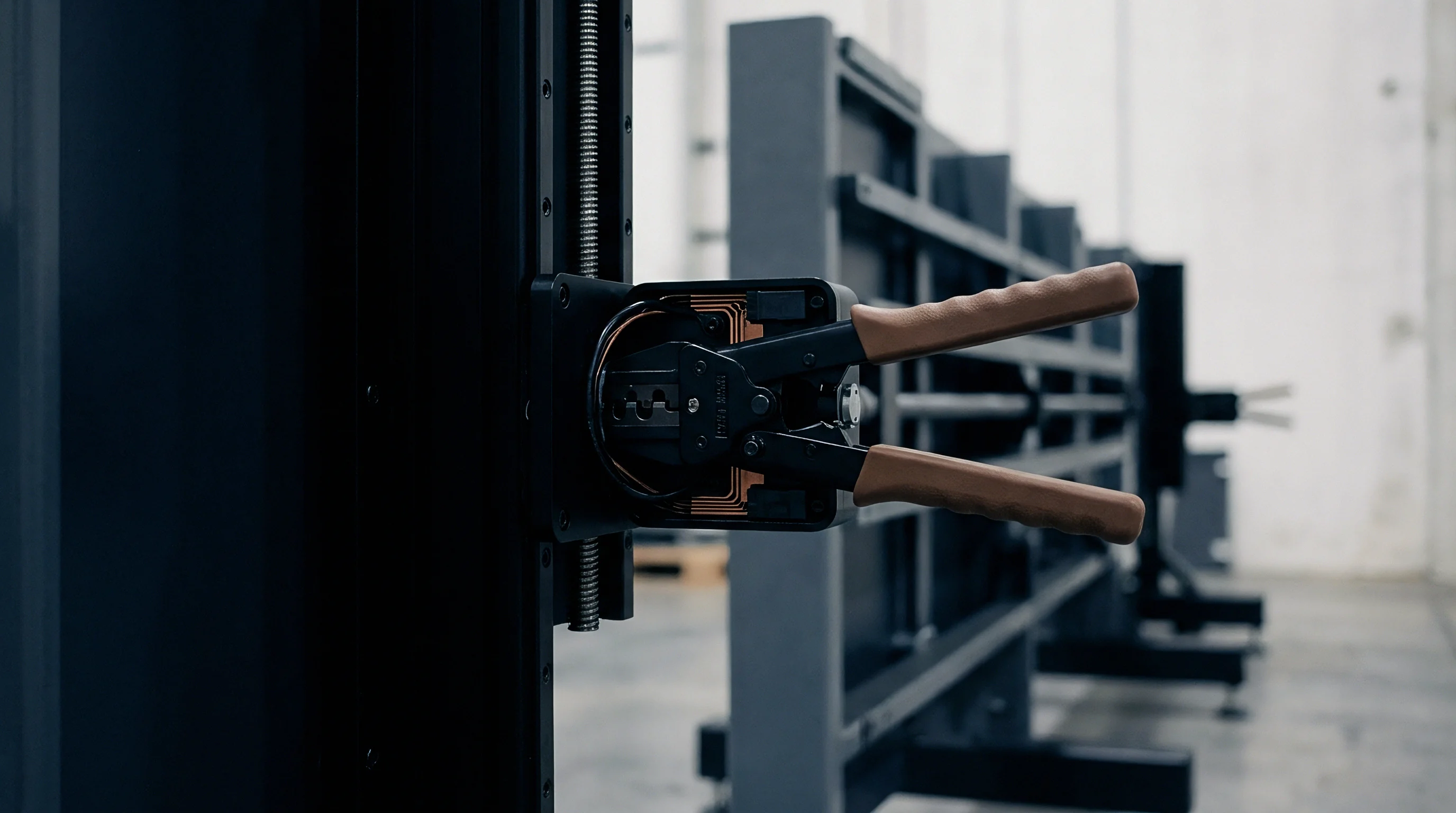
Liquid phase deposition along the internal pipe perimeter creates an insulating hydraulic sleeve. The thickness of this annular film depends on superficial gas velocity, fluid surface tension, and liquid wall shear stress. In wet gas systems with Lockhart-Martinelli parameters below 0.05, the wall film thickness varies between 0.15 and 0.85 millimeters.
Oil films suppress convective transfer. Within this thin band of liquid, the temperature profile transitions from the pipe wall temperature to the core stream temperature.

Where Do Viscous Sublayers Skew Phase Fractions?
Differential velocity between dense hydrocarbon liquids and continuous gas cores generates severe shear at the transport boundary. This shear thins the hydraulic boundary layer while thermal boundary layers expand or contract based on fluid Prandtl numbers. For light hydrocarbon gases, the Prandtl number hovers near 0.8, producing comparable thermal and hydrodynamic boundary layers.
For viscous crude oil films, the Prandtl number climbs past 85, confining the thermal gradient to an extremely thin sublayer adjacent to the steel wall.
Electrical impedance sensors, including dual-energy gamma meters and radio-frequency resonance probes, interrogate the pipe volume by projecting electric or electromagnetic fields across the cross-section. The measured dielectric permittivity and electrical conductivity of the multiphase mixture depend heavily on local fluid temperature. For formation water, conductivity changes by approximately 2.1 percent per kelvin.
When an uninsulated pipe wall chills the perimeter film, impedance meters overestimate the water film volume fraction because colder saline water exhibits reduced electrical conductivity that sensor calibration algorithms mistake for hydrocarbon volume.
A radial thermal gradient of 3.8 kelvin across the laminar sublayer produces an uncorrected fluid density error of 0.42 percent in heavy crude oil systems at 40 bar.
Phase slip alters radial temperature gradients. In gas-dominant flows, high-pressure natural gas experiences Joule-Thomson cooling across meter venturis or restrictive sensor throats. The localized temperature depression drops core temperatures by 3 to 7 kelvin relative to the upstream pipe wall.
Sensor elements positioned flush with the internal wall measure the insulated liquid boundary rather than the expanding core gas. The thermal discrepancy corrupts the equation of state computations that transform measured operational density into standard cubic meters.
| Flow Regime | Film Thickness (mm) | Radial Delta T (K) | Boundary Biot Number | Phase Hold-Up Bias (%) | Expanded Uncertainty (k=2) |
|---|---|---|---|---|---|
| Stratified Smooth | 1.20 to 3.40 | 5.20 | 0.14 | +1.85 | 0.62% |
| Wavy Annular | 0.45 to 1.10 | 3.80 | 0.38 | -2.40 | 0.88% |
| Dispersed Bubble | 0.08 to 0.25 | 1.10 | 1.25 | +0.45 | 0.31% |
| Slug Flow Body | 2.50 to 8.00 | 6.40 | 0.06 | +3.15 | 1.15% |
| Chrun Flow Mist | 0.20 to 0.60 | 2.90 | 0.55 | -1.60 | 0.74% |
Boundary conditions fluctuate wildly between pure single-phase flow and transient multiphase flows. Chilled pipe spools distort energy equations. Meter designs that assume logarithmic temperature profiles fail when the liquid film alternates between laminar conduction and turbulent wave breaking.
During liquid slug passage, the boundary layer strips away instantly, exposing the wall to bulk liquid temperatures before reforming as an insulating film in the subsequent gas pocket.
Thermal boundary errors manifest through distinct physical interactions within sensor bodies:
- Thermal Expansion Mismatch shifts internal flow tube dimensions in Coriolis multiphase meters, altering the structural moment of inertia when pipe skin resistance thermometers lag behind the oscillating fluid boundary.
- Conductive Shunting draws heat along sensor mounting bosses and thermowell stems, distorting the local fluid temperature profile before the stream reaches the active measurement junction.
- Permittivity Drift corrupts capacitance-based phase fraction sensing as cold wall oil films alter dielectric constants independent of actual gas volume fraction changes.
- Acoustic Refraction bends ultrasonic interrogation paths across steep sound-speed gradients caused by thermal boundary stratification in high-pressure gas streams.
Flow regimes govern local heat flux. Measuring multiphase fluids without compensating for wall heat transfer equates to treating a fluctuating thermodynamic heat exchanger as an isothermal pipe spool.


Shear
Velocity vectors across the pipe diameter collapse into steep profiles when fluid viscosity climbs past thirty centistokes. Viscous crude drags the thermal profile. In high-viscosity multiphase streams, internal viscous dissipation generates localized frictional heating within the near-wall boundary layer.
This shear-induced dissipation creates positive temperature spikes along the wall while the central flow remains colder, reversing the conventional direction of heat flux.

Whose Flow Facility Replicates Process Shear Conditions?
Accredited calibration loops typically operate with refined mineral oils or potable water under ambient pressure. Standard test benches circulate fluids at Reynolds numbers exceeding 100,000 to maintain turbulent conditions. Industrial production pipelines often operate in the transitional or laminar-turbulent boundary regime with Reynolds numbers between 2,500 and 15,000.
Under these transitional conditions, wall shear stress governs the boundary layer thickness, and factory flow loops cannot replicate the shear-dominated thermal profile encountered in the field.
Coriolis meters deployed on multiphase pipelines encounter particular difficulties. The meter operates by vibrating one or two curved or straight measuring tubes at their natural resonance frequency. The meter software computes mass flow from the Coriolis force phase shift and fluid density from the resonance frequency.
Tube stiffness is directly proportional to the Young’s modulus of the tube alloy, typically Titanium Grade 9 or Hastelloy C-22, which shifts by roughly minus 0.04 percent per kelvin. High viscosity slumps wall shear stress.
API Manual of Petroleum Measurement Standards Chapter 20 Section 3 penalizes undocumented fluid property shifts by disqualifying meter factors from commercial allocation.
To compensate for metal temperature changes, Coriolis meters mount resistance temperature detectors on the exterior tube skin. When a steep thermal boundary layer develops inside the tube, the external RTD tracks the tube outer surface temperature, while the internal tube surface experiences differing boundary temperatures governed by fluid shear. The resulting cross-wall thermal stress alters the structural stiffness of the tube.
The sensor electronics apply an erroneous modulus compensation factor, injecting a systematic bias into both the mass flow computation and the resonant density reading.
Evaluating multiphase sensor uncertainty demands rigorous review of operational calibration parameters:
- Apparent Viscosity Range verifies that calibration fluid viscosity envelopes the operational shear-rate spectrum of the process crude.
- External Heat Transfer Coefficient accounts for insulation performance, convection rates from ambient cross-winds, and conductive heat losses through pipeline support clamps.
- Wall Shear Rate Concordance confirms that the test loop matches operational wall shear stress rather than simple gross volumetric flow rate.
- Temperature Sensor Immersion Depth prevents thermowells from resting entirely within the thermal boundary layer without sampling the bulk velocity-weighted core stream.
- Dynamic Pressure Decompression models thermal shifts generated by localized Joule-Thomson cooling across internal differential pressure restrictions.
Wet gas regimes amplify boundary thinning. During disputes, manufacturers insist that external RTDs track process fluid temperatures within factory specifications whenever the flow tube remains encased in original thermal cladding.


Audit
Third party review teams dissecting allocation imbalances encounter calibration logbooks that record pure thermodynamic equilibrium. Steady states take hours to establish. In field audits, true thermal equilibrium between the pipeline wall and the multiphase flow stream almost never occurs.
Rapid production choke changes, intermittent gas lift cycling, and diurnal ambient temperature swings keep the thermal boundary layer in constant flux.

Boundary Layer Uncertainty Budget Formulation
Combining individual variance elements under JCGM 100 guidelines relies on rigorous partial derivatives for each thermal transfer coefficient. Single phase testing hides fluid coupling. To quantify the unresolved boundary layer uncertainty, the metrologist must isolate the thermal conduction error term across the pipe wall, the phase hold-up temperature sensitivity, and the structural sensor modulus drift.
Summing these terms in quadrature yields an expanded uncertainty that frequently dwarfs the nominal calibration uncertainty stated on the manufacturer certificate.
Matching the Reynolds number without matching the Prandtl number guarantees divergent thermal boundary layers.
The standard Guide to the Expression of Uncertainty in Measurement dictates that systematic biases with known signs cannot remain as uncompensated offsets; they must be corrected, and the uncertainty of the correction applied to the budget. If the thermal boundary layer profile is unmeasured, the correction cannot be computed. The entire boundary effect converts into a Type B rectangular distribution, heavily inflating the combined uncertainty.
| Facility Type | Test Fluids | Operating Pressure (bar) | Thermal Wall Control | Radial Delta T Matching | Traceability Link |
|---|---|---|---|---|---|
| Single Phase Water Loop | Fresh Water | 1 to 6 | None (Ambient Air) | Uncontrolled | National Standard Gravimetric |
| Atmospheric Oil-Gas Rig | Exxsol / Nitrogen | 2 to 10 | Passive Insulation | Zero Heat Flux Mode | Volumetric Master Meter |
| High Pressure Multiphase | Crude / Methane / Brine | 20 to 120 | Chilled Jacket Control | Simulated Field Gradient | Dual Gravimetric Weigh Tanks |
| Wet Gas Venturi Loop | Decane / Natural Gas | 40 to 90 | Active Fluid Tracing | Core-to-Wall Cooling | Cross-Checked Piston Prover |
Settling calibration disputes requires executing an audit sequence that exposes missing thermodynamic boundary terms before commercial claims reach formal arbitration:
- Extract continuous pipe skin and core fluid temperature logs across the disputed production period, identifying all episodes where radial differentials exceed 1.5 kelvin.
- Calculate the instantaneous operational Prandtl and Nusselt numbers for each distinct flow regime based on fluid sampling PVT analyses.
- Determine the boundary layer thermal resistance by modeling conductive heat transfer through the pipe wall, sensor liner, and internal fluid film.
- Recalculate sensor phase fraction outputs using the thermal boundary layer gradient corrections across the interrogation volume.
- Recompute cumulative mass and standard volume totals under the adjusted meter factors, generating revised balance sheets for joint venture partners.
Density imbalances accelerate annular stratification. API MPMS Chapter 5 Section 6 Clause 4.2 dictates that calibration proving procedures remain invalid if fluid operating temperatures diverge from proving temperatures by more than 0.5 kelvin without active mathematical compensation.

Exposure
Offshore production sharing contracts assign operating deficits based on raw mass allocation balances calculated at platform export manifolds. Pipe wall conduction skews boundary readings. When unquantified thermal boundary layers introduce systematic offsets into custody meters, the resulting equity imbalance compounds across months of baseline operation.

Fiscal Allocation Reconciliation across Equity Partners
Commercial agreements enforce pipeline tariffs through volumetric balancing models updated every twenty four hours. Uncorrected boundary profiles compound fiscal exposure. If an uninsulated subsea tieback meter underreports water cut by 2.0 percent due to cold wall impedance distortion, dry oil production is systematically over-allocated to that satellite field.
The downstream export terminal eventually identifies the excess formation water during bulk separation, forcing reconciliation audits where the operator of the dry asset pays the cost of the misallocated volume.
Unallocated hydrocarbon fractions inevitably transfer cash balances to the operator with the warmest flowline.
The magnitude of financial exposure depends directly on cumulative throughput, prevailing hydrocarbon spot prices, and the steepness of the radial boundary gradient. In multi-field trunklines handling 80,000 barrels per day, a 1.2 percent unresolved thermal boundary layer error shifts tens of thousands of barrels of oil equivalent over a single financial quarter.
| Production Stream | Gross Rate (BOE/Day) | Boundary Layer Bias (%) | Annual Volume Error (BOE) | Assumed Price ($/BOE) | Total Financial Exposure ($) |
|---|---|---|---|---|---|
| Deepwater Heavy Crude | 25,000 | -1.85% | -168,812 | 72.00 | 12,154,464 |
| Condensate Wet Gas | 45,000 | +1.10% | +180,675 | 65.00 | 11,743,875 |
| Subsea Marginal Tieback | 8,500 | -3.20% | -99,280 | 75.00 | 7,446,000 |
| High Water Cut Gathering | 60,000 | +0.75% | +164,250 | 70.00 | 11,497,500 |
| Trunkline Network Balance | 138,500 | Unweighted Mean 1.72% | 613,017 Total Vol | Mean 70.50 | 42,841,839 Cumulative Sum |
Factory certificates ignore viscous boundary layers. When calibration disputes land before formal arbitration tribunals, technical experts must prove whether stated factory uncertainties cover actual dynamic field boundary conditions or represent purely ideal isothermal loop behavior. What criteria will future multiphase calibration standards establish to mandate full boundary layer thermodynamic modeling on commercial calibration certificates?