Computerized Architecture
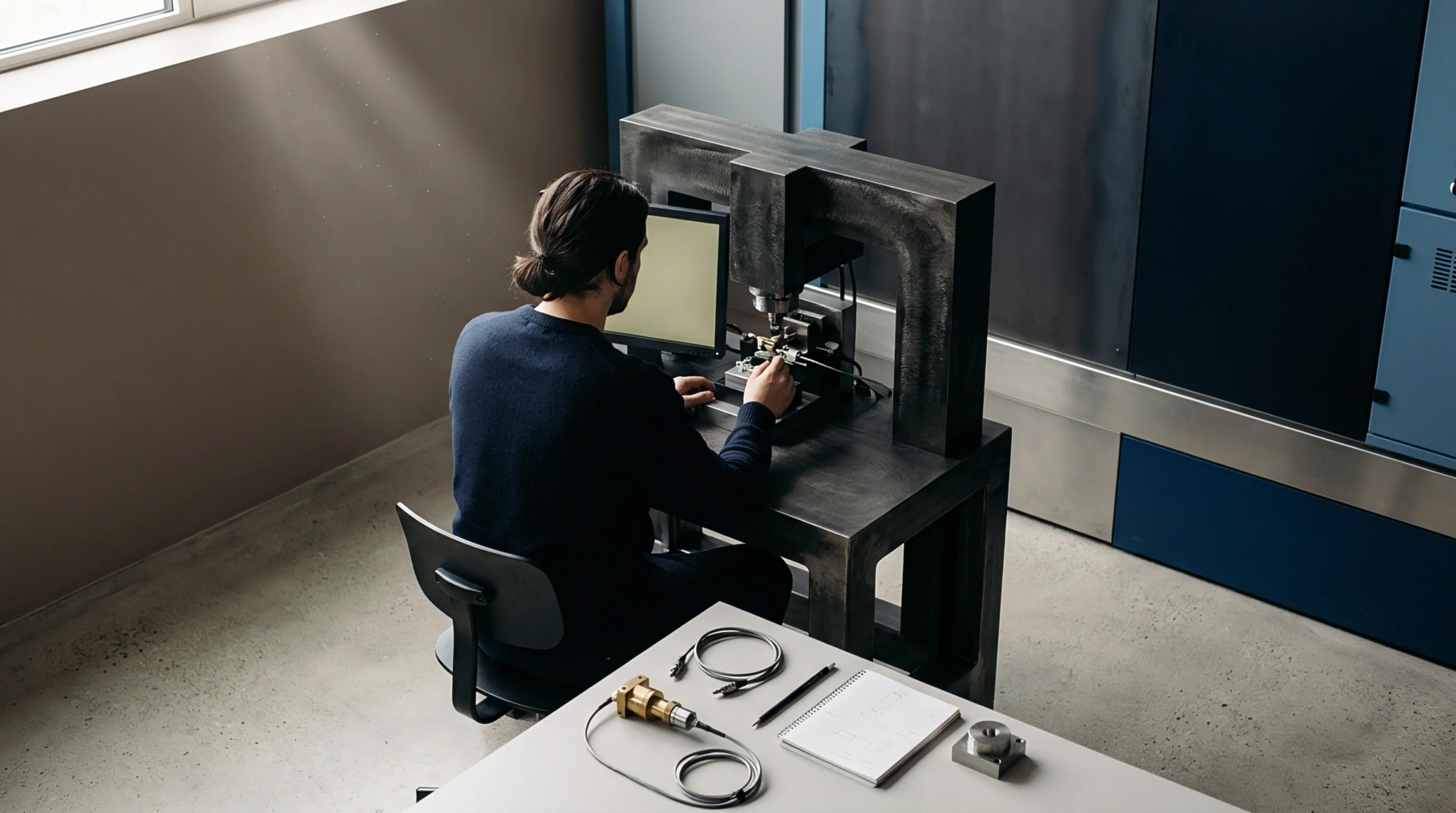
Centralized measurement hardware manages the high speed evaluation of electronic circuits using programmed sequences. In high volume manufacturing, automated test equipment coordinates the delivery of power, signals and load conditions to each device on the production line. This integration replaces manual bench checks with a repeatable software driven interface.
The system measures current, voltage and timing parameters against a predefined set of pass boundaries. It identifies failed components early in the workflow to prevent wasteful downstream processing. The scope of the hardware includes the test head, the mainframe and the specific interface adapters known as probe cards or load boards.
These components ensure that every connection is electrically sound and geographically aligned with the pads of the product.
Metrological Precision
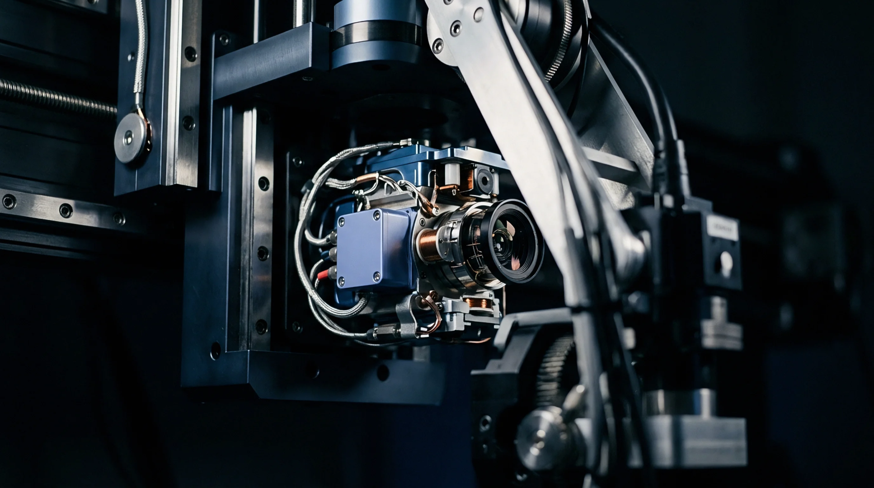
Signal accuracy determines the reliability of the binning process used to sort good units from bad ones. Inside the chassis, automated test equipment contains precision source measure units and digital pin cards. Every instrument undergoes regular calibration against traceable standards to minimize drift during long operation shifts.
If the timing jitter increases beyond the specification, the system might reject functional items due to false alarms. Sourcing these systems involves assessing the total measurement uncertainty at the specific frequencies used by the target chip. Temperature variations inside the test floor can degrade the accuracy of high resolution analog to digital converters.
Proper thermal control around the tester racks prevents these fluctuations from impacting the guard bands. Regular verification runs with golden samples confirm that the calibration stays within acceptable tolerances.
Integration Interface
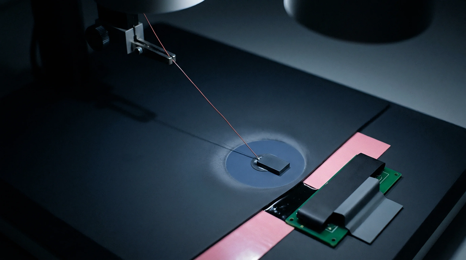
Probing mechanics link the electrical mainframe to the physical locations on the semiconductor wafer. For effective use, automated test equipment relies on low resistance paths through the interface hardware. If the contact force is inconsistent, the measured resistance will fluctuate and create phantom failures.
Sourcing reliable interface boards requires high specifications for impedance matching and thermal expansion resistance. Over many thousands of cycles, the pins of the tester head suffer from physical wear or accumulation of debris. This interference adds noise to the data streams and reduces the efficiency of the measurement path.
Maintenance protocols dictate the frequency of pin cleaning and replacement schedules. Engineers verify the integrity of the signal chain by executing loopback tests that verify each path without the device in place.
Diagnostic Outcome
Final reports aggregate the measurement results to provide a profile of the overall batch quality. After the sequence ends, automated test equipment assigns each unit to a logical bin based on performance metrics. These metrics follow specific logic paths defined in the test plan to ensure coverage of all critical failure modes.
If a pattern of failures emerges, it provides data for process engineers to adjust the fabrication steps upstream. The system stores these logs for traceability and future reliability analysis of the component family. Limits on the tester capacity dictate how many chips can be measured simultaneously without sacrificing signal power.
Advanced versions use massive parallelism to keep the throughput consistent with the speeds of the assembly lines. The unit functions as the primary gate for hardware quality control in the modern factory.