Strain Potential
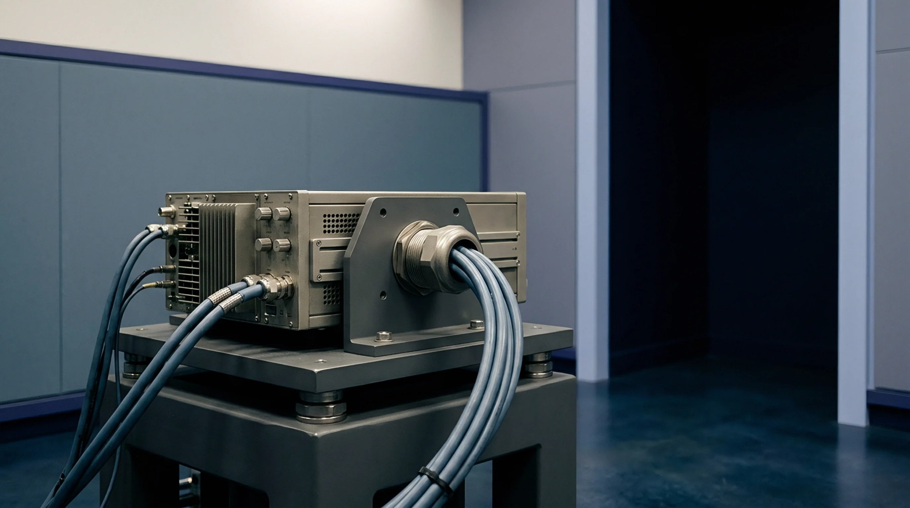
Internal interaction between applied mechanical stress and the electrical resistivity of a material converts physical force directly into a measurable change in current flow. Utilization of piezoresistive coupling forms the physical basis for many modern pressure sensors and strain gauges integrated into industrial equipment. In semi-conducting materials like silicon, this effect is significantly stronger than simple geometric shifts in lead wires.
When a crystal is stretched or compressed, the energy bands inside the lattice reorganize, which alters how easily electrons move through the structure. This creates a predictable shift in resistance that is proportional to the magnitude of the external influence. Measurement modules pick up these signals using high resolution bridge circuits to determine weight, pressure or acceleration.
High sensitivity makes this technique preferable for low pressure detection in cleanroom monitoring.
Signal Linearity
Consistency of the resistor response ensures that the resulting data translates accurately across the entire intended range of the sensor. Within the logic of piezoresistive coupling, the relationship between strain and resistance is mathematically modeled to minimize output errors. Designers place resistors along specific axes of the crystal lattice to maximize sensitivity while minimizing the impact of transverse noise.
If the orientations are incorrect, the device will respond to forces from the wrong directions, leading to contamination of the data stream. Temperature often acts as a complicating factor by altering the baseline resistivity of the sensor independently of the strain. Integrated compensation loops utilize nearby diodes to measure the temperature and subtract this drift from the final output.
Regular check-ins against standard references ensure that this linearity persists as the sensor ages.
Interface Bridge
Integration of four discrete resistors into a balanced layout helps isolate the desired signal from environmental interferences. Application of piezoresistive coupling frequently involves a Wheatstone bridge where two elements extend under pressure while the other two contract. This layout doubles the output signal while cancelling common errors like thermal expansion of the package body.
A stabilized voltage source provides excitation to the bridge, and the differential voltage at the center points represents the sensed load. If the resistances are perfectly matched at zero force, the bridge remains balanced with zero output. Deviations during manufacturing can lead to initial zero offsets that are trimmed out during factory calibration.
High performance amplifiers then bring these micro-volt shifts up to standard industrial ranges like four to twenty milliamps.
Measurement Boundary
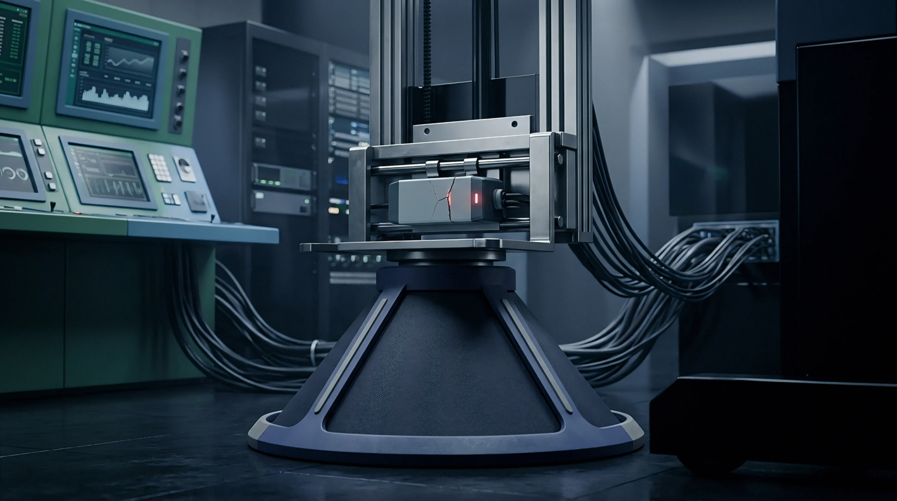
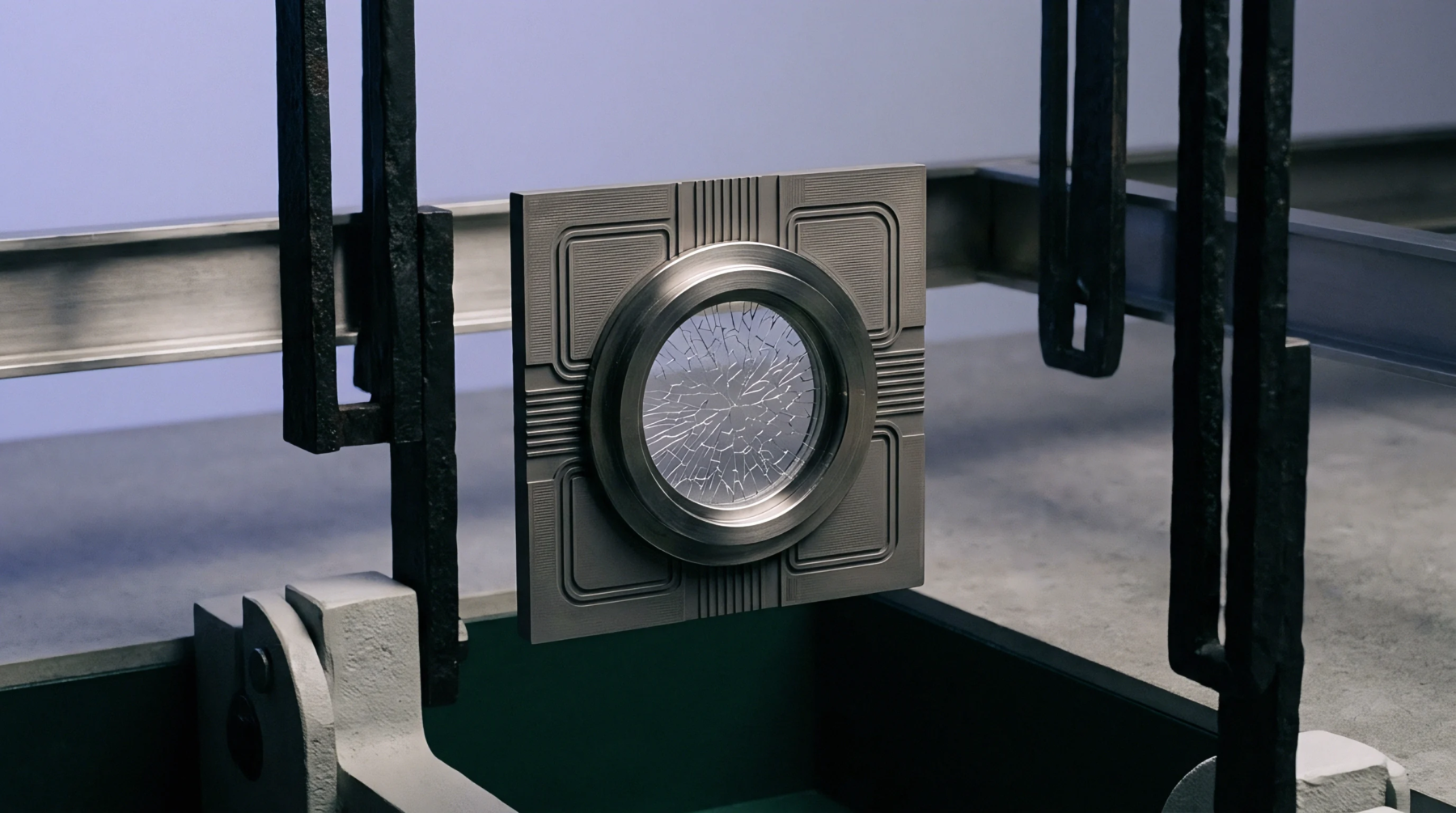
Accuracy limits for these sensors rest at the point where the material reaches its elastic limit or where noise floors obscure subtle changes. The effectiveness of piezoresistive coupling stops being useful when the material undergoes permanent deformation, which destroys the original calibration logic. At extremely high stresses, the resistance changes may become non-linear, requiring complex lookup tables to resolve correctly.
Thermal noise from the movement of atoms inside the sensor also limits the lowest detectable signal. Design boundaries specify the maximum allowable over-pressure to prevent damage to the delicate internal sensing beams. Verification of these limits requires test cycles where instruments are pushed near their breaking points to observe structural health.
Continued use within rated specifications guarantees stable performance over the design life.