Mitigating Package Strain in Wafer Level Accelerometers
Mitigating package strain in wafer level accelerometers requires decoupling the sensing core using silicon etch trenches, high-standoff bumps, and compliant RDLs.

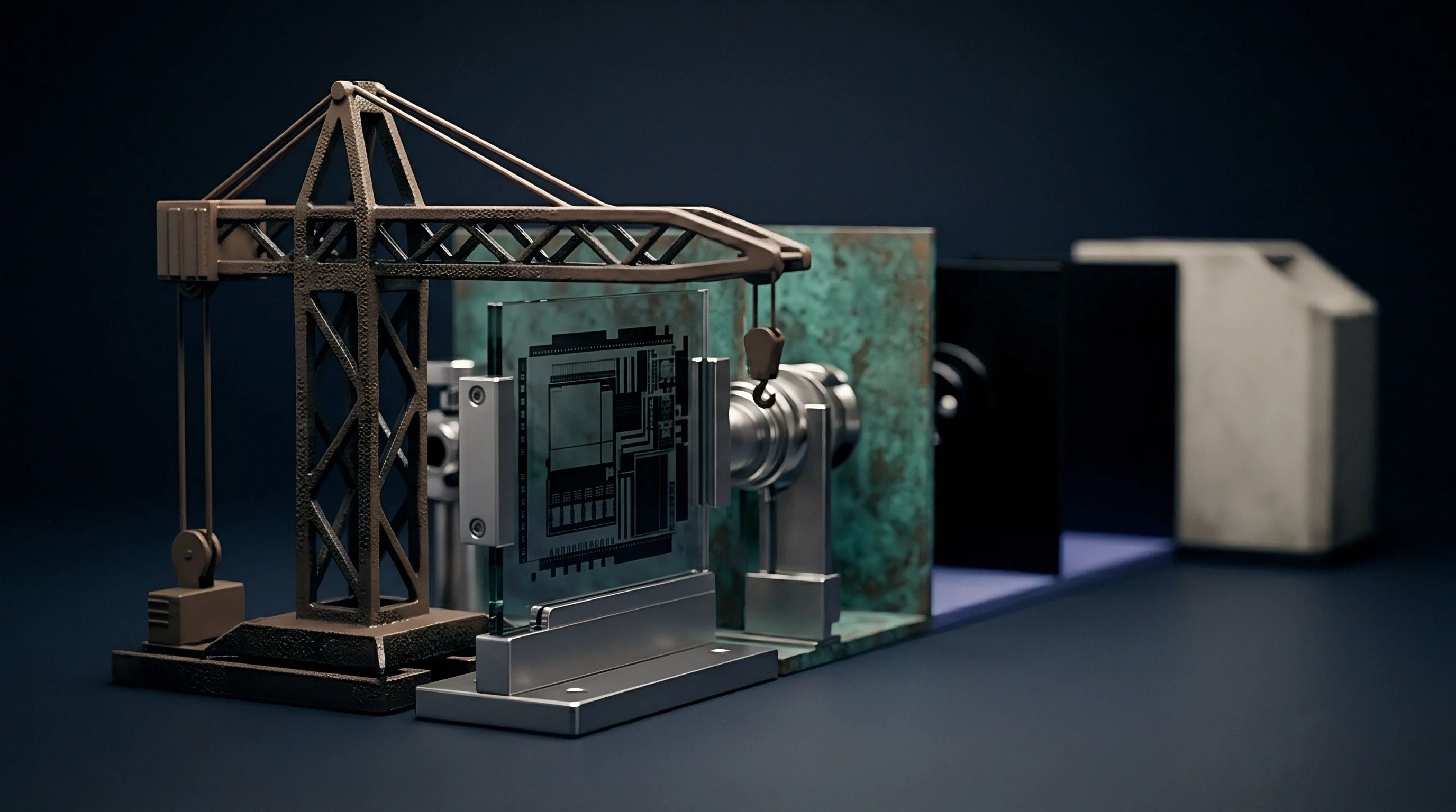
Offset
Directly soldering bare silicon onto an organic printed circuit board leaves the microelectromechanical sensing element exposed to unbuffered thermal and mechanical deformation. Wafer level chip scale packaging omits the protective mold compound and intermediate leadframe substrate found in standard quad flat no-lead assemblies to trim footprint and height. Silicon’s isotropic coefficient of thermal expansion is 2.6 parts per million per Kelvin, while standard FR4 laminate substrates range between 14 and 17 parts per million per Kelvin in-plane.
As the assembled board cools from the SAC305 liquidus temperature of 217 degrees Celsius down to ambient operational levels, this contraction mismatch loads the silicon die with severe compressive biaxial stress.
Reflow cooling freezes residual shear stress into the assembly, often exceeding 80 megapascals near the active sensor perimeter. For differential capacitive accelerometers, substrate deformation warps suspension anchors and pulls fixed sensing fingers out of alignment with the suspended proof mass. In a sub-two-micron sensing gap, an anchor shift of just two nanometers creates a measurable zero-g bias offset.
While differential architectures reject symmetric common-mode strain across opposing capacitor pairs, stress gradients across the die face still drive asymmetric variations in finger pitch.
A temperature shift of 40 degrees Celsius produces an uncompensated zero-g bias shift exceeding 35 milli-g in 0.8-millimeter WLCSP accelerometers lacking mechanical isolation.
Capacitive gaps shift whenever the substrate deflects. As thermal gradients travel across the host board during warm-up, transient asymmetric strains bypass factory calibration registers and register as physical acceleration. In systems that rely on long-term baseline stability ~ like dead reckoning or structural tilt monitoring ~ unmanaged package stress effectively renders the sensor specification sheet useless.

Piezoresistive Coupling to Die Curvature
Bending moments transmitted through solder joints change the electrical resistivity of doped silicon via piezoresistive coupling. Even on capacitive devices, integrated signal conditioning circuitry and on-chip reference resistors remain susceptible to mechanical modulation. The longitudinal and transverse piezoresistive coefficients of p-type silicon along the crystal orientation amplify shear stress components, shifting the quiescent reference voltage fed to the analog-to-digital converter.
Mechanical twisting of the sensor substrate rotates the sensitive axis out of its calibrated planar orientation, creating cross-axis coupling error that registers as lateral acceleration during pure vertical shock loads. Silicon has anisotropic elastic stiffness; Young’s modulus varies from 130 gigapascals along the direction to 169 gigapascals along the plane. Because of this crystal anisotropy, even isotropic thermal expansion mismatches produce non-uniform, asymmetric warpage profiles across square dies.
- Suspension anchor tilting rotates the proof mass hinge plane, shifting the zero-g output by several tens of milli-g per micrometer of substrate deflection.
- Capacitive gap modulation alters the nominal open-circuit pickoff capacitance, degrading electrostatic balance across closed-loop feedback nodes.
- Piezoresistive reference shift alters the bandgap reference bias current, inducing thermal scale factor drift up to 120 parts per million per Kelvin.
- Comb finger pull-in vulnerability reduces the mechanical shock threshold when external out-of-plane warpage closes differential electrostatic travel stops.
Thermal hysteresis leaves behind uncompensated errors. As an assembly cycles between minus 40 and plus 85 degrees Celsius, the solder interconnects experience ongoing plastic deformation and creep relaxation. Consequently, the stress profile inside the silicon never returns to its starting state after a temperature loop, creating a permanent offset shift that software calibration cannot reliably eliminate.
| Package Topology | Die Thickness (microns) | Peak Silicon Stress (MPa) | Post-Reflow Zero-g Shift (mg) | Thermal Hysteresis (minus 40 to 85 C, mg) |
|---|---|---|---|---|
| Standard WLCSP (Bare Die) | 400 | 115 | 45 to 80 | 12 to 25 |
| WLCSP with Thick Polyimide RDL | 400 | 68 | 22 to 38 | 5 to 11 |
| WLCSP with DRIE Stress Trench | 300 | 32 | 8 to 15 | 2 to 5 |
| Pre-Molded Cavity LGA | 500 | 18 | 4 to 9 | 1 to 3 |
| Overmolded Molded LGA | 500 | 54 | 18 to 32 | 4 to 8 |
Deploying wafer level accelerometers without controlling solder-induced curvature leads to systematic zero-g drift that can consume the host microcontroller’s entire calibration budget during initial assembly.


Trench
Etching physical isolation barriers directly into the silicon substrate interrupts the acoustic and mechanical path between external solder contacts and the central sensing element. Deep Reactive Ion Etching cuts narrow vertical slots partially or fully through the device wafer or encapsulation cap. These air gaps redirect the stress field, forcing mechanical strains from board bending to dissipate around the outer perimeter rather than reaching the proof mass anchors.
Forming micro-springs out of the monolithic silicon layer lets the internal transducer island float inside a rigid surrounding boundary frame. When board twisting pushes peripheral solder joints out of plane, compliant suspension beams deflect elastically to absorb the displacement. As a result, the central proof mass and counter-electrodes experience less than one-tenth of the external strain field.
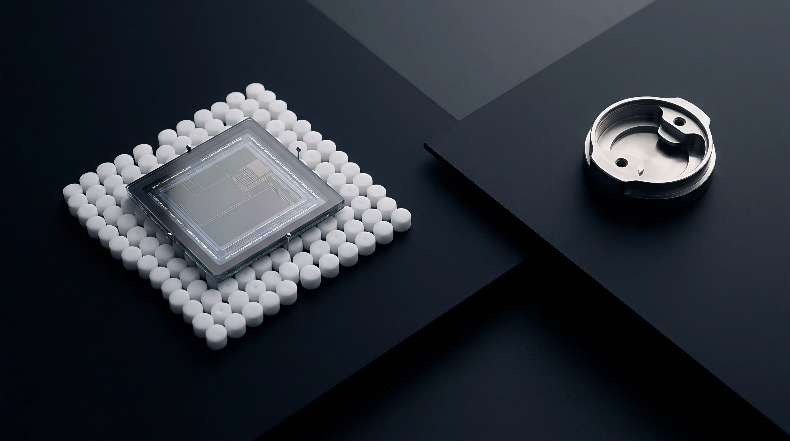
Through Silicon Etching for Mechanical Isolation
Deep silicon etching enables aspect ratios beyond thirty to one, yielding isolation channels five to ten micrometers wide through wafers three hundred micrometers thick. Alternating plasma etching steps between sulfur hexafluoride and octafluorocyclobutane passivation yields smooth, vertical sidewalls free of micro-notch stress concentrators. Notch imperfections along an etch profile weaken the fracture toughness of single-crystal silicon, making the die vulnerable to brittle fracture under shock or drop events.
Placing the suspension anchor along the neutral mechanical axis of the isolated island minimizes sensitivity to substrate bending. Symmetric slot layouts distribute thermal expansion stresses evenly across opposing sides, canceling common-mode translational movement before it can tilt or displace the capacitive pickoff plates.
- Monolithic isolation beams route board warpage around the central core, attenuating external strain transmission by more than twenty decibels.
- Perimeter barrier trenches intercept crack propagation paths originated at dicing street micro-fractures, improving mechanical drop survival.
- Cantilevered anchor islands decouple the sensing diaphragm from package shear stresses, maintaining zero-g offset stability over temperature.
- Corner stress reliefs prevent solder joint stress concentration from migrating inward toward fragile capping wafer seal rings.
Complete through-wafer trenches add manufacturing complexity by requiring temporary carrier wafer bonding during backside processing. Any particle contamination or adhesive void on the carrier compromises wafer planarity, leading to localized lithographic defocus during subsequent metallization steps.
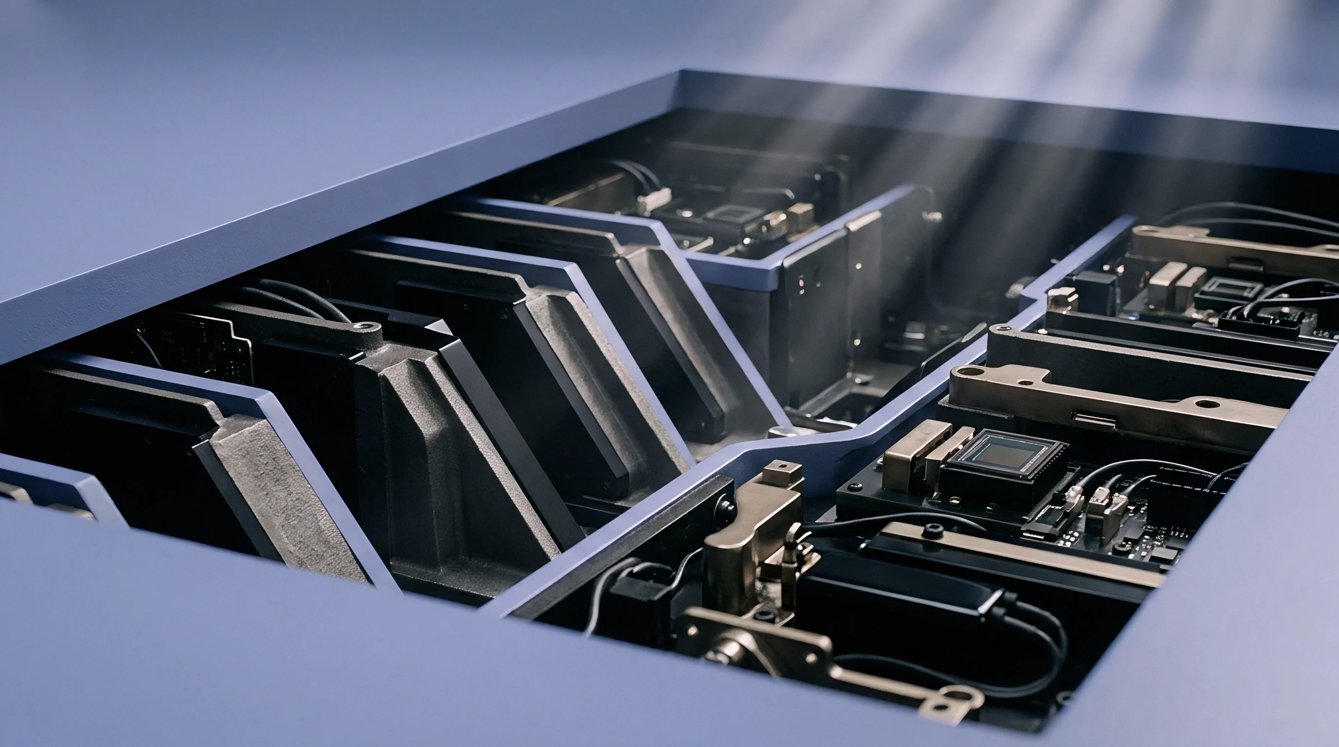
Cap Wafer Cavity Geometries
The capping wafer shields sensitive microstructures while acting as an active mechanical barrier. Silicon direct fusion bonding, glass frit bonding, and eutectic systems (like aluminum-germanium or gold-tin) create hermetic seals around the internal cavity. Glass frit bonding adds relatively thick intermediate layers with thermal expansion coefficients near 7 ppm/K, establishing a thermal expansion gradient against the silicon cap.
Narrow eutectic seal rings allow isolation channels to sit closer to the proof mass cavity, maximizing the die surface dedicated to strain attenuation. Step-etched recesses on the capping wafer keep the top of the package from coming into mechanical contact with mold compounds or external housings.
Whether wafer-level isolation channels can maintain vacuum cavity hermeticity through twenty years of continuous automotive thermal shock testing remains an open question.


Solder
Interconnect metallurgy and standoff height determine how efficiently mechanical strain transfers from the circuit board into the silicon die. Standard SAC305 ball grid array bumps (tin, 3.0 percent silver, 0.5 percent copper) have an elastic modulus around 50 gigapascals at room temperature, transferring displacement straightforwardly into the die. Shear strain within the joint is simply the differential thermal expansion displacement divided by standoff height.
Copper pillar bumps with solder micro-caps hold the die 60 to 80 micrometers above the board, easily outperforming collapsed sphere joints that manage standoffs of barely 35 micrometers. The solid copper column acts as a lever arm, taking up shear displacement through elastic and plastic flex in the solder cap while dampening the stress wave moving into the silicon.
A solder standoff increase from 40 to 75 micrometers cuts the transmission of board-level bending strain to the active MEMS cavity by 46 percent under monotonic bend testing.
The outermost corner bumps take the heaviest shear loads, accumulating plastic strain with every thermal cycle. When shear stress exceeds the yield strength of the bulk alloy, micro-voids form along the intermetallic compound boundary, causing open circuits or erratic bias jumps as stored stress releases.

Alloy Metallurgy and Standoff Geometry
Low-temperature alloys lower the residual stress baseline by reducing the solidification point. Bismuth formulations like Sn42Bi58 melt at 138 degrees Celsius, narrowing the temperature span during post-reflow cooling. This smaller thermal span cuts residual assembly stress by roughly 40 percent compared to standard SAC305 profiles.
The main metallurgical trade-off is brittleness: tin-bismuth alloys offer minimal ductile yield, making them vulnerable to high-g shock loads. In subsea and marine systems, similar lead-free joint embrittlement prompted extensive qualification testing to track intermetallic phase growth over long thermal dwells. For wafer-level sensors, picking an alloy comes down to balancing thermal drift reduction against mechanical shock survival.
| Interconnect Configuration | Standoff Height (microns) | Alloy Composition | Elastic Modulus (GPa) | Offset Shift Post-Reflow (mg) | Drop Test Survival (Cycles to Fail) |
|---|---|---|---|---|---|
| Standard Spherical Ball | 45 | SAC305 | 51 | 65 | 120 |
| High-Standoff Sphere | 75 | SAC305 | 51 | 38 | 210 |
| Copper Pillar Micro-Bump | 80 | Cu / SAC105 cap | 110 (Cu) / 42 (cap) | 28 | 450 |
| Low-Temperature Bismuth Bump | 45 | Sn42Bi58 | 44 | 22 | 45 |
| Polyimide-Buffered Copper Pillar | 85 | Cu / Sn-Ag cap | 3.5 (PI) / 110 (Cu) | 14 | 600 |
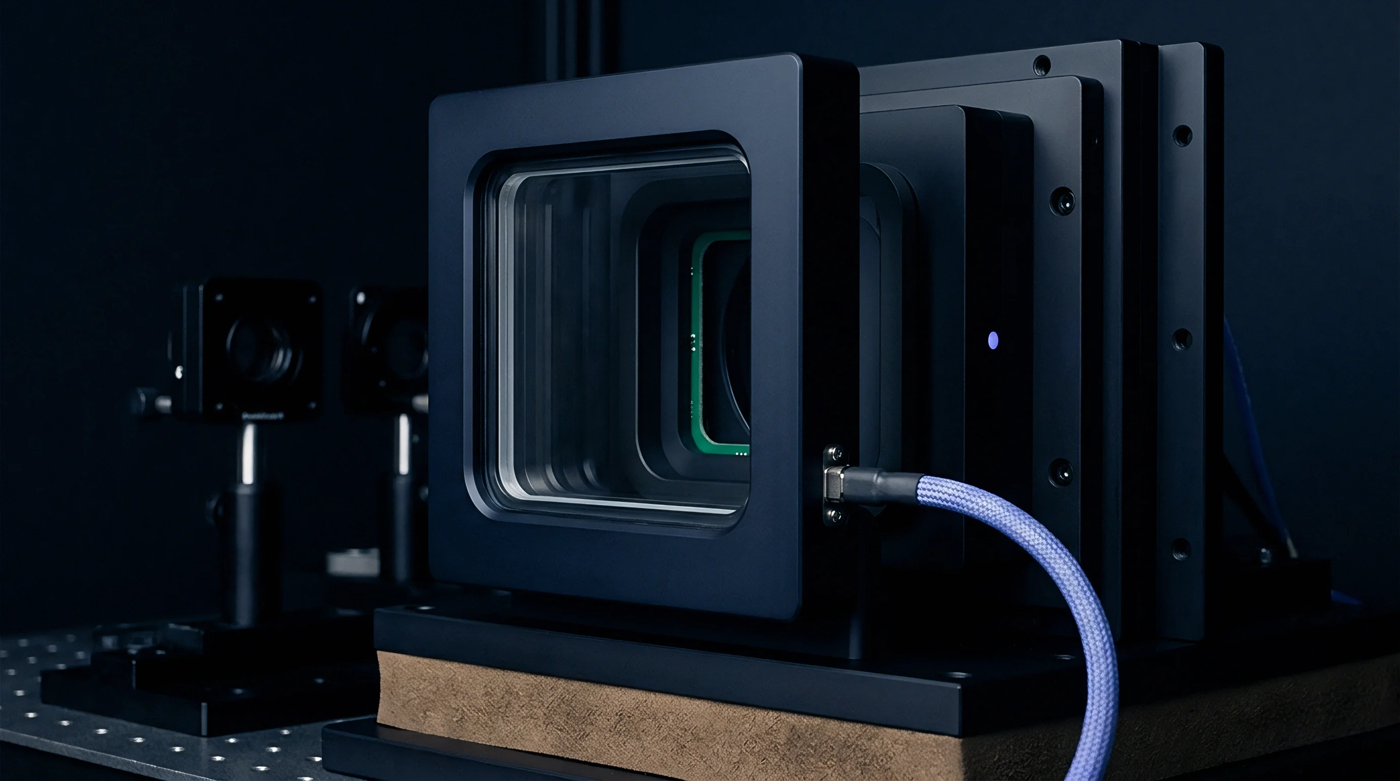
Polyimide Redistribution Layer Attenuation
Placing polyimide redistribution layers between the silicon substrate and under-bump metallization creates a viscoelastic mechanical buffer. Photosensitive polyimides have an elastic modulus between 2.5 and 4.0 gigapascals ~ two orders of magnitude lower than silicon. A thick polyimide cushion (five to twelve micrometers) permits local lateral flex at the solder pads without transmitting high peel forces to the passivation layer.
Using multiple redistribution layers allows signal routing to move away from high-stress die edges toward the quieter central region. Placing active solder balls solely in the central zone while leaving outer pads depopulated substantially shortens the moment arm through which board warpage can twist the internal accelerometer proof mass.
Industry literature frequently cites 30 megapascals as the threshold where package stress degrades capacitive comb alignment, though that figure originates from older four-millimeter packaging and does not hold up predictably on sub-millimeter wafer-level dies. Design teams should treat 30 megapascals as an unverified guideline and measure actual offset drift on their specific board stackup.
Standard redistribution layers reduce transmitted stress, but post-assembly calibration failures still occur when reflow ramp rates or mounting conditions induce uncompensated strains.


Underfill
Applying polymeric underfill beneath a wafer level chip scale package fundamentally alters the sensor’s mechanical boundary conditions. Capillary underfills ~ epoxy resins loaded with silica filler ~ are mainly used to improve drop-test durability by distributing shock loads across the full die footprint rather than individual solder joints. However, the polymer bonds the silicon die directly to the laminate substrate across its bottom face, stripping away the mechanical compliance of open air standoffs.
As underfill cures at elevated temperatures (typically 130 to 150 degrees Celsius), chemical cross-linking contracts the material by 1.5 to 3.0 percent by volume. This shrinkage exerts high triaxial tension on the die surface. Cooling back to room temperature magnifies the strain, since the underfill’s coefficient of thermal expansion (25 to 45 ppm/K) far exceeds that of silicon.
A contract clause mandating zero underfill dispense within three millimeters of an accelerometer package prevents board assemblers from treating the sensor like a standard digital microcontroller.
Direct mechanical coupling to the board shifts the structural resonance modes of the packaged silicon, sometimes driving parasitic package resonances straight into the operational bandwidth of the accelerometer. This acoustic path feeds high-frequency board vibration directly into the active sensing cavity, causing severe signal rectification errors.

Capillary Dispense and Viscoelastic Relaxation
Capillary action draws liquid underfill under the die, drawing on surface tension and substrate preheating to fill the gap without voids. Uneven dispensing creates unequal fillet heights along the die edges. An asymmetric fillet pulls unevenly on opposite sides, generating diagonal bending moments that warp the capacitive pickoff comb fingers.
The mechanical properties of epoxy evolve over time under continuous mechanical load. After assembly, cured underfill undergoes gradual molecular realignment, causing the sensor’s zero-g offset to drift over weeks of room-temperature storage. Thermal cycling speeds up this creep, making a stable baseline calibration difficult to maintain.
- Glass transition temperature clearance prevents the operating temperature envelope from intersecting the polymer phase change zone where modulus shifts tenfold.
- Silica filler concentration control tailors the coefficient of thermal expansion, balancing stress reduction against dispensing viscosity limits.
- Fillet height symmetry management balances lateral tension forces across opposing die edges, preventing induced diagonal warpage modes.
- Hygroscopic expansion mitigation curtails package swelling under high-humidity operating environments, suppressing seasonal zero-g drift.
Published figures for underfill-induced zero-bias drift range from 5 to 50 milli-g depending on cure profile and board thickness, making in-situ offset logging across fifty thermal cycles on the actual production board assembly necessary before finalizing manufacturing drawings.
Glass Transition Temperature Dynamics
The glass transition temperature marks the threshold where an underfill shifts from a stiff, high-modulus state to a compliant, rubbery one. Typical underfills have glass transition temperatures between 120 and 150 degrees Celsius. Crossing this threshold causes the storage modulus to drop by up to two orders of magnitude, while the thermal expansion coefficient jumps sharply from 30 ppm/K to over 90 ppm/K.
When glass transition occurs within or near the operational range of an industrial or automotive sensor (minus 40 to plus 105 degrees Celsius), mechanical boundary conditions change non-linearly. The resulting zero-g offset curve shows sharp discontinuities that polynomial calibration registers in the sensor ASIC cannot correct.
Dispensing small droplets of high-modulus structural adhesive strictly at the four corners of the wafer level package secures drop-shock resistance while leaving the active central cavity decoupled from the board laminate.
IEC 60749-10 defines mechanical shock test requirements for semiconductor devices; updating assembly files to specify corner bonding instead of full capillary underfill maintains compliance without compromising accelerometer DC stability.


Placement
Layout geometry and board construction dictate the external stress fields reaching a wafer level accelerometer. Circuit boards are anisotropic composites of woven fiberglass cloth and epoxy resin with patterned copper layers. Asymmetric copper distribution between top and bottom layers forces the board to bow and twist during thermal cycling, subjecting an accelerometer on an unbalanced stackup to substantial bending moments.
Connecting solder balls with traces of unequal width or mismatched routing directions creates localized stiffness variations and uneven wetting during reflow. Pad type also alters joint mechanics: non-solder-mask-defined pads let solder grip the edges of the copper land, producing a more symmetrical, compliant joint that distributes strain evenly.
Placing an unshielded wafer level accelerometer within thirty millimeters of a structural chassis mounting fastener guarantees sensor offset failure during automated torque-driver assembly.
Proper trace layout preserves the sensor’s internal rejection capability by ensuring external mechanical strains enter the die symmetrically along its primary geometric axes rather than diagonally across corner bumps.

Circuit Board Copper Balance and Trace Symmetry
Copper has a thermal expansion coefficient of 16.5 ppm/K, while FR4 resin expands at over 50 ppm/K out-of-plane and 15 ppm/K in-plane. Imbalanced copper coverage between top and bottom signal layers drives dynamic board warpage as systems warm up. Solid copper ground planes placed directly under the package act as local heat sinks, distorting reflow cooling across neighboring solder joints.
When trace routing requires varying line widths, teardrop transitions and solder mask dams prevent solder from wicking away from the pad. Unequal solder volume tilts the die relative to the board surface, introducing permanent off-axis errors into the output registers.
| Layout Parameter | Distance to Feature (mm) | Applied Mechanical Load | Zero-g Bias Shift (mg) | Substrate Curvature (1/m) |
|---|---|---|---|---|
| Structural Screw Boss | 5 | 0.4 Nm Fastener Torque | 85 | 0.142 |
| Structural Screw Boss | 20 | 0.4 Nm Fastener Torque | 14 | 0.022 |
| Structural Screw Boss | 35 | 0.4 Nm Fastener Torque | 2 | 0.003 |
| Board Cutout Slot | 2 | 1.0 mm Monotonic Flexure | 6 | 0.008 |
| Solid Board Edge | 2 | 1.0 mm Monotonic Flexure | 42 | 0.068 |
| Depaneling Punch Boundary | 3 | Mechanical Punch Shear | 120 | 0.195 |

Mechanical Keep out Zones around Fasteners
Mounting screws, snap fits, and enclosure tabs apply localized compressive loads that propagate through the board dielectric. Torquing a standard M2 chassis screw to 0.4 Newton-meters produces board deflections up to twenty-five millimeters from the screw hole. Placing an accelerometer within this radius exposes the sensor to permanent offset shifts during drop impacts or thermal expansion.
Milling a U-shaped slot through the board laminate on three sides of the accelerometer creates an isolated cantilever tab. This compliant tongue absorbs outer board flexure, shielding the sensor from enclosure-induced strain without adding secondary carrier substrates.
Mechanical punch depaneling or pizza-cutter singulation generates peak shear strains exceeding 1500 micro-strain near board edges. Using laser routing or low-stress tab routing during singulation protects factory zero-g calibration from immediate destruction.
Aligning the sensitive axes parallel to the enclosure’s main structural stiffeners minimizes parasitic bending moments over the product’s operating lifespan.