Interfacial Stress Transfer Mechanics and Dynamic Thermal Sensor Offset Drift
Substrate strain transfer across package interfaces generates dynamic thermal sensor offset drift during transient temperature ramps.

Shear
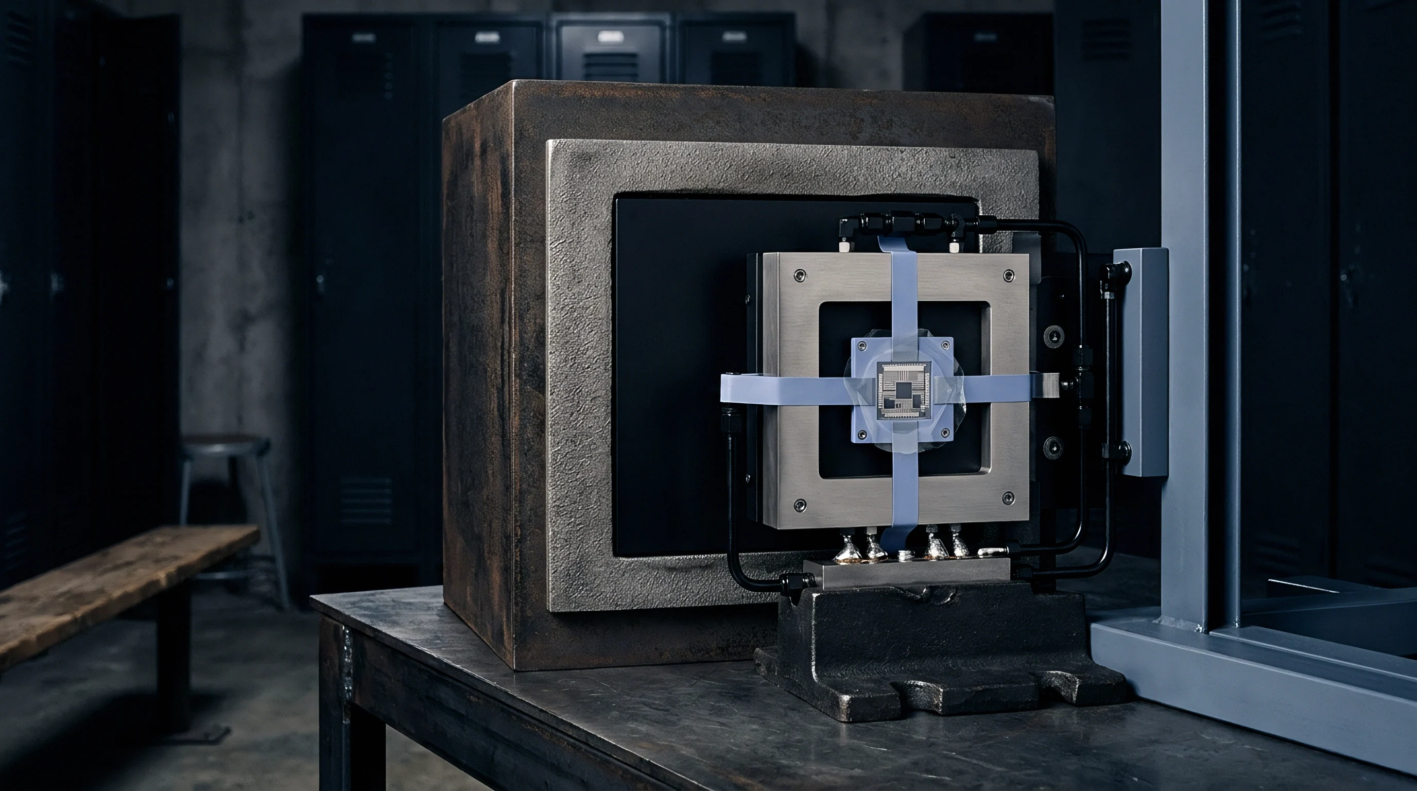
Surface-mounted thermal sensors endure mechanical forces transmitted from the underlying printed circuit board through solder joints, leadframes, die-attach adhesives, and plastic encapsulants. Differential thermal expansion arises because each material in the stack-up has a distinct coefficient of thermal expansion. Standard FR-4 substrate material expands at approximately fourteen to seventeen parts per million per Kelvin in the planar axis, whereas silicon expands at approximately two point six parts per million per Kelvin.
Solder alloys and epoxy mold compounds bridge this thermomechanical mismatch, creating interfacial shear stresses across the boundaries of the assembly.
Mechanical stress alters the electrical parameters of integrated silicon structures through the piezoresistive effect. In silicon bandgap thermal sensors, temperature measurement relies on matching the operating voltages of bipolar transistors running at different current densities. When planar shear stress and normal stress field gradients act upon the die, piezoresistive coefficients shift collector currents and alter resistor ratio balances.
| Material Stack Layer | Young’s Modulus (GPa) | Coefficient of Thermal Expansion (ppm/K) | Thermal Conductivity (W/mK) |
|---|---|---|---|
| Silicon Die Substrate | 130.0 | 2.6 | 148.0 |
| Silver-Filled Epoxy Die Attach | 5.5 | 35.0 | 2.5 |
| Copper Alloy Leadframe | 120.0 | 16.5 | 385.0 |
| Epoxy Mold Compound (EMC) | 22.0 | 12.0 | 0.8 |
| SAC305 Lead-Free Solder | 48.0 | 21.5 | 58.0 |
| FR-4 Glass-Epoxy Laminate | 24.0 | 15.0 | 0.3 |
Interfacial shear stress transmits according to shear lag models where the die-attach layer absorbs part of the mechanical strain. Thick, compliant adhesives with a low shear modulus reduce stress coupling between leadframe and silicon, whereas hard, highly filled epoxies carry planar strain straight to the active surface of the die. Below the glass transition temperature of the packaging polymer, elastic modulus rises sharply, transferring more strain onto the sensing elements.
Viscoelastic relaxation of the mold compound then produces time-dependent baseline shifts after large temperature swings.
Silver-filled epoxy die-attach adhesives exhibit a shear modulus jump from 1.2 GPa above glass transition to 6.5 GPa below eighty degrees Celsius.
Thermal ramp baseline shifts frequently stem from structural modulus shifts in encapsulating mold compounds rather than printed circuit board warpage.


Gradient

Transient Thermal Rates and Differential Expansion
Rapid atmospheric or structural thermal transients drive temperature gradients across sensor packaging boundaries. Heat moves inward from outer encapsulants toward the silicon die, creating temporary temperature differences between package leads, corner mold volumes, and the central semiconductor junction. During steep thermal ramps, the center of the die lags behind the peripheral mounting pads in temperature.
These thermal gradients induce uneven structural expansion, setting up localized bending moments across the silicon substrate. Differential planar stress components alter transistor current gains in sensitive analog signal paths, generating dynamic offset drift ~ temperature reading errors that appear during thermal ramps and fade once isothermal conditions return.

Piezoresistive Coupling to Bandgap References
The piezoresistive tensor for single-crystal silicon dictates that normal stresses along orthogonal crystal axes modify carrier mobility and junction barrier potentials. Consequently, bipolar junction transistors arranged in differential configurations experience asymmetric offset shifts when subjected to directional stress gradients.
- Transient asymmetry ~ Uneven heat ingress across die corners generates differential planar shear, bending the substrate differential pair.
- Glass transition hysteresis ~ Mold compound passes through glass transition during thermal ramps, producing non-linear modulus changes that lag temperature readings.
- Viscoelastic stress relaxation ~ Epoxy polymers settle slowly post-ramp, driving calibration drift that persists for minutes after isothermal stabilization.
- Package lead asymmetry ~ Differential thermal expansion across asymmetrical copper traces shifts anchor forces directly into the package frame.
Solder solidifies under high mechanical strain, while stress relaxation inside plastic packages follows an exponential decay profile. When temperature rates reach several degrees per second, dynamic stress forces push bandgap reference offsets past commercial accuracy limits. How effectively multi-die stacked packages isolate sensitive thermal references from substrate shear remains unquantified across high slew rates.


Layout

Does Board Relief Layout Reduce Dynamic Offset Drift?
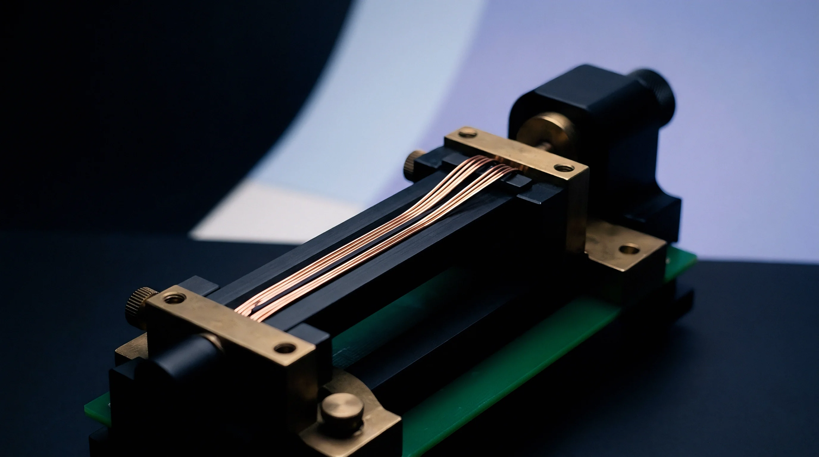
Printed circuit board design controls how much strain reaches the sensor terminals. Board thickness, copper weight, trace routing, and land pattern geometry dictate mechanical impedance around the package footprint. Heavy copper pours tied directly to sensor pins increase local stiffness, transferring board flexure into the component leadframe.
Integrating mechanical isolation slots around the sensor footprint decouples board flexure from the package. U-shaped or rectangular cutouts routed through the board laminate reduce strain transmission caused by structural flexing, thermal expansion from adjacent power components, and enclosure mounting points.
| Package Variant | Board Strain Coupling Ratio (%) | Dynamic Slew Drift (mK / K per s) | Solder Joint Shear Stress (MPa) | Package Footprint Area (mm²) |
|---|---|---|---|---|
| WLCSP-4 (Wafer Level) | 88.0 | 140.0 | 42.5 | 1.44 |
| DFN-6 (2×2 mm Exposed Pad) | 64.0 | 85.0 | 28.0 | 4.00 |
| SOIC-8 (Gull-Wing Leads) | 22.0 | 18.0 | 12.0 | 30.50 |
| Ceramic LCC-8 (Hermetic) | 12.0 | 5.0 | 18.5 | 9.00 |
Land Pattern Optimization and Footprint Geometry
Solder joint geometry directly influences stress delivery to package leads. Perimeter land patterns with enlarged outer toe fillets add mechanical strength but transmit greater planar shear into the package. Small land patterns without soldering on the center exposed pad reduce mechanical coupling, though they increase thermal resistance to the board.
Routing mechanical relief slots along three sides of a surface-mount sensor footprint reduces board-induced strain transfer by more than sixty percent.
- Isolation slot milling ~ Route keyhole slots around the sensor footprint to decouple board flexure strain from the land pattern.
- Symmetrical land pattern ~ Equalize solder pad areas and thermal relief traces to prevent asymmetric pulling forces during reflow solidification.
- Thermal mass balance ~ Connect sensor signal tracks to symmetrical copper trace geometries to eliminate directional thermal conduction pathways.
- Component placement radius ~ Maintain a fifteen-millimeter clearance from board mounting screws, stiffeners, and heavy connectors.
Omitting thermal isolation cutouts on thick multi-layer assemblies pushes dynamic thermal reading errors beyond published accuracy bands during rapid heating cycles.

Register

Bus Communication and Digital Compensation Mechanics
Digital thermal sensors transmit temperature data over standard serial buses, including I2C and SPI interfaces. Host microcontrollers read internal conversion registers populated by on-chip analog-to-digital converters, while internal digital filtering algorithms process raw ADC outputs to attenuate noise and thermal transients. Bus registers store these transient values, and clock speed dictates polling intervals.
Firmware can reduce dynamic offset drift by applying derivative compensation formulas. Evaluating the temperature rate of change over time allows host software to subtract stress-induced shifts calculated from characterized package strain coefficients, updating the compensated output according to modeled transient response curves.
Modelling this transient thermal response requires extracting the baseline thermal time constant of the package. The raw register reading undergoes digital high-pass rate detection combined with gain scaling to offset internal stress hysteresis, running continuous multiply-accumulate operations within host driver loops.
Offset Voltage Shift: Δ Vos = π44 · τxy + (π11 – π12) · fracσx – σy2
Firmware Temperature Calculation: Tcomp = Traw – Kstress · fracTraw – Traw Δ t
Higher polling rates over the I2C bus increase power dissipation inside the package, introducing self-heating thermal gradients across the silicon. Microcontroller firmware must balance update frequencies against thermal dissipation targets to prevent internal temperature offsets.
JEDEC standard JESD22-A104 Clause 4.2 dictates thermal slew rates between ten and fifteen degrees Celsius per minute for board-level stress qualification.
High-order digital filtering of transient sensor outputs adds firmware latency that degrades control loop phase margin in fast thermal systems.


Audit

Verification Methodologies and Test Bench Procedures
Empirical verification of dynamic offset drift requires environmental test chambers capable of precise linear temperature ramps. Instrumented circuit boards fitted with integrated strain rosettes measure mechanical strain concurrently with digital register telemetry, tracking surface deformation throughout the ramp.
Quantifying stress-induced offset drift requires controlled thermal cycling while logging differential temperature output errors against calibrated reference probes. The verification sequence tracks stress relaxation curves over extended dwell times.
- Mount populated sensor test boards into an environmental chamber equipped with digital strain monitoring.
- Apply a linear thermal ramp from minus forty degrees Celsius to one hundred twenty-five degrees Celsius at five degrees per minute.
- Log real-time differential temperature error outputs via SPI bus while recording rosette strain gauge values.
- Compare isothermal equilibrium offsets against transient slew offsets to compute the package dynamic stress coefficient.
- Subject test samples to five hundred thermal cycles before repeating the dynamic slew audit to measure hysteresis degradation.
Component qualification profiles follow standard environmental stress testing directives. AEC-Q100 standards define thermal cycling parameters for automotive-grade silicon devices, specifying the temperature ranges and cycle counts needed to evaluate packaging stress endurance.
Purchase specifications incorporating IPC-9701 performance test methods reject component lots exhibiting post-reflow dynamic offset shifts greater than two hundred millikelvin.


Outlay

Commercial Trade-Offs and Package Selection Strategy
Thermal sensor sourcing involves selecting package forms that balance unit procurement price, printed circuit board processing complexity, and firmware development requirements. Semiconductor manufacturers offer identical sensor silicon across multiple packaging variants, ranging from wafer-level chip-scale packages to metal-can housings. Unit cost often dictates selection at high volume, though packaging choices ultimately govern final yield.
| Packaging Format | Unit Cost at 100k Volume (USD) | Post-Assembly Calibration Yield Loss (%) | Firmware Bring-Up Effort (Weeks) | Total Landed Cost per Placed Unit (USD) |
|---|---|---|---|---|
| WLCSP (Wafer Level) | 0.32 | 4.5 | 3.0 | 0.48 |
| DFN-6 (Plastic Surface Mount) | 0.45 | 1.2 | 1.5 | 0.58 |
| SOIC-8 (Leaded Package) | 0.68 | 0.3 | 0.5 | 0.79 |
| Ceramic LCC-8 (Hermetic) | 2.85 | 0.05 | 0.5 | 3.05 |
Wafer-level chip-scale packaging provides the lowest component purchase price and smallest footprint. However, physical substrate strain couples directly into the unencapsulated die, requiring strain relief slots in the board and digital rate-of-change compensation drivers in firmware. Assembly yield directly impacts the final landed cost.
Leaded packages such as SOIC-8 or gull-wing SSOP forms increase unit component cost while isolating internal silicon from PCB bending forces. Flexible copper leads absorb thermal expansion mismatches, reducing dynamic offset drift without requiring specialized board routing or complex host compensation algorithms.
Selecting an unencapsulated wafer-level package reduces component unit price while shifting mechanical strain management entirely onto the board layout.
Selecting the appropriate packaging tier ultimately balances initial acquisition price against total landed manufacturing yields and system-level firmware effort.