Minimizing Surface Mount Sensor Baseline Drift through Substrate Routing Slots
Milling substrate routing slots around surface mount sensors isolates package pads from board bending and CTE mismatch strain to prevent baseline drift.


Shear
Surface mount MEMS elements experience mechanical displacement when the underlying laminate expands or contracts under thermal load. Differential thermal expansion creates severe stress. Standard FR-4 glass-epoxy laminate exhibits an in-plane coefficient of thermal expansion ranging from 14 to 17 ppm/K. Silicon sensor dies feature an in-plane thermal expansion coefficient of approximately 2.6 ppm/K. When components undergo reflow or operating ambient temperature shifts, this coefficient differential generates lateral strain across solder joints.
Surface mount packages such as Land Grid Array (LGA) and Quad Flat No-Lead (QFN) mount directly to PCB pads with thin solder joints. Die stress alters electrical output. Up to 80 percent of mechanical strain in the PCB passes into the encapsulation mold compound and sensor cavity.
In piezoresistive pressure transducers and MEMS gyroscopes, this mechanical stress flexes the internal silicon diaphragm or proof mass suspension. The mechanical deformation alters piezoresistive element values, resulting in zero-point baseline drift.
| Package Type | Footprint Area (mm) | Substrate Strain Transfer Ratio (%) | Zero-Point Shift per 100 µm Flex (FS) |
|---|---|---|---|
| WLCSP-8 | 1.5 x 1.5 | 35 to 45 | 0.12 % |
| LGA-12 | 2.0 x 2.0 | 60 to 70 | 0.35 % |
| QFN-16 | 3.0 x 3.0 | 75 to 85 | 0.68 % |
| SOIC-8 | 4.9 x 3.9 | 20 to 30 | 0.08 % |
Fastener torque flexes the board. Tightening PCB mounting screws to 0.4 Nm in an aluminum enclosure induces mechanical deflection spanning 50 to 200 micrometers across a ten-millimeter span. This mechanical bending produces baseline offset shifts that easily exceed datasheet initial calibration tolerances.
Placing an isolation cut between structural mounting holes and sensitive package pads prevents enclosure strain from reaching the sensor cavity.
Ignoring thermal expansion mismatch between board materials and sensor packages leads to baseline drift values that breach system accuracy limits in operational fields.


Bridge
Substrate isolation cutouts physically detach the component landing area from surrounding laminate strain fields. Router bit diameter dictates slot width. Milling open slots around three sides of a sensor footprint creates a cantilevered PCB island.
Mechanical stress traveling through the main board panel cannot easily cross open air gaps, forcing strain lines around the isolated section.

Mechanical Island Topologies
Mechanical island suspension relies on narrow PCB bridges to carry power, ground, and communication traces. Bridge width dictates both strain attenuation and mechanical resonance. Narrow bridges reduce strain transmission.
A bridge width measuring 1.2 mm to 1.5 mm provides structural stability during surface mount placement while attenuating low-frequency bending strain by 14 dB to 20 dB. Slot widths created by standard 1.0 mm or 1.6 mm end mills prevent mechanical contact between the island and the outer board panel under 2 g vibration loads.

Slot Geometry Parameters
Slot path design governs total flex isolation. A continuous C-shaped slot isolating three sides of a square footprint forms a flexible cantilever arm. A dual U-slot design isolates four corners while leaving two narrow connecting bridges on opposing edges.
Under an applied board flexure of 1.0 mm per 100 mm span, mechanical strain at the center of a solid board reaches 650 microstrain. On a slotted cantilever island measuring 5.0 mm by 5.0 mm, strain drops to 85 microstrain, representing an 87 percent reduction in mechanical coupling to package landing pads.

Trace Routing across Isolation Cutouts
Copper bridges carry power signals. Traces crossing substrate isolation slots run across the mechanical bridges. Routing signal conductors over open substrate slots causes trace fracture during thermal cycling due to differential expansion across the gap.
Inner layer copper planes on the mechanical island require electrical isolation from the main board reference plane, using single-point ground ties across the bridge to prevent ground loop noise while maintaining signal return paths.
- Bridge Fracturing occurs when panel depaneling tools apply torsional loads across narrow mechanical suspensions without sacrificial support tabs.
- Trace Fatigue happens when signal lines cross unrouted substrate slots without solid laminate backing underneath the copper layer.
- Impedance Discontinuity develops when differential communication pairs cross isolation trenches without continuous ground reference planes.
A dual-slot cantilever layout reduces strain transfer by 78 percent under a 100-micrometer substrate deflection test condition.
Fabricators frequently assert that mechanical slots below one millimeter in width cause premature end-mill breakage and increase panel scrap rates.


Offset
Digital sensor die architectures incorporate internal digital-to-analog converters and gain stages to correct zero-point deviations prior to data output. Physical strain alters baseline values. When strain reaches the silicon sensing element, the zero-point voltage shifts, introducing offset error into the digital output word.

How Does Host Firmware Distinguish Strain from Signal?
Software filters cannot remove stress. A host processor reading I2C registers cannot differentiate between genuine environmental pressure changes and mechanical strain induced by circuit board warp. Physical strain mitigation at the substrate level lowers stress-induced drift below the LSB threshold of high-resolution analog front ends.
Physical strain alters baseline values across temperature bands. Digital interfaces like SPI and I2C allow register-level zero-point offset writing. Writing baseline calibration values to non-volatile sensor registers compensates for static reflow offset.
Static register adjustments fail to compensate for dynamic mechanical stress caused by thermal cycling or enclosure chassis flex. Isolating the sensor footprint using substrate slots keeps dynamic zero-point drift within ±0.5 percent of full-scale span across operating temperatures from -40°C to +105°C.
Clock lines require solid return paths. When routing digital lines over substrate bridges, SPI clock lines operating at 10 MHz require adjacent ground return traces on the bridge to prevent EMI emissions and signal degradation.
- Power on the sensor assembly and establish I2C communication at 400 kHz.
- Read the raw zero-point register value after allowing five minutes for thermal stabilization.
- Apply target enclosure screw torque while streaming sensor output registers to quantify mechanical strain transfer.
- Verify that residual zero-point variation stays within two least significant bits of nominal rating.
IPC-2221A Section 9.2 specifies minimum conductor spacing to slot edges to prevent insulation breakdown under mechanical stress.
The long-term stability of digital calibration registers under continuous cyclic vibration remains an unquantified variable across high-volume production batches.

Reflow
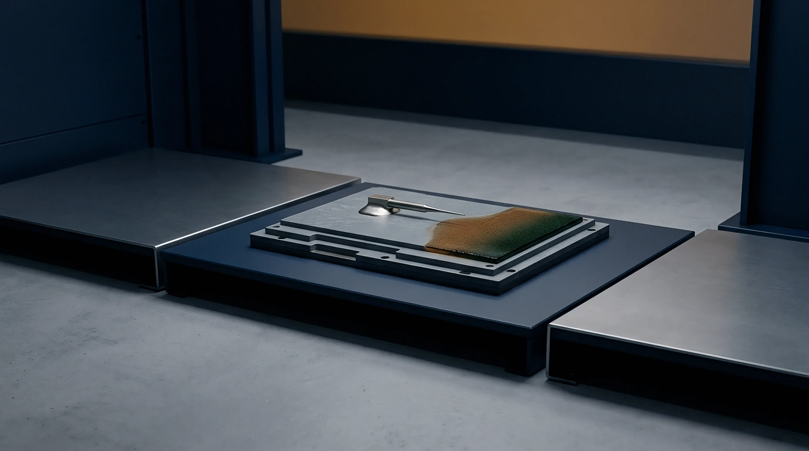
Solidification of lead-free SAC305 solder creates static stress fields inside surface-mount package terminations. Thermal cycles shift solder geometry. During reflow assembly, board laminate and leadless packages heat up to 260°C peak temperatures.
As liquid solder cools below 217°C, differential thermal contraction locks mechanical tension into the solder joints.

Land Pattern Geometry Controls
Land pattern design alters stress distribution across package corner leads. Extending copper landing pads 0.15 mm past the package footprint perimeter allows solder fillets to form complete toe surfaces, distributing strain away from fragile die interconnects. Thermal pads under LGA packages require segmented solder paste apertures to avoid excessive solder volume that lifts package corners during reflow.

Stencil Design for Stress Reduction
Reduced paste volume lowers stiffness. Stencil aperture design influences solder joint volume and height. High solder joint height increases compliance, absorbing differential expansion between package pads and substrate copper.
Standard stencil thickness of 127 micrometers combined with 1:1 pad aperture ratios yields rigid solder fillets that transmit high stress. Reducing stencil aperture area to 85 percent of pad area using rounded square patterns reduces solder volume, yielding optimal fillet geometry for stress absorption.
| Aperture Area Ratio (%) | Stencil Thickness (µm) | Stand-off Height (µm) | Post-Reflow Baseline Offset Shift (LSB) |
|---|---|---|---|
| 100 | 127 | 35 ±5 | 14.2 |
| 90 | 127 | 42 ±4 | 9.6 |
| 85 | 100 | 48 ±3 | 4.1 |
| 75 | 100 | 55 ±4 | 3.8 |
Substrate routing slots allow isolated PCB islands to expand freely during reflow without resistance from surrounding panel areas. Thermal expansion isolation prevents asymmetric package tilting and solder bridging on bottom-terminated components.
Solder fillet height directly modulates the mechanical stiffness of bottom-terminated sensor packages.
Solder stencil designs that reduce paste volume on inner ground pads decrease mechanical baseline shift without compromising thermal dissipation.

Tooling
Panel layout design determines the manufacturing expenditure incurred during printed circuit board fabrication. Board fabricators enforce minimum radii. Incorporating substrate routing slots into PCB master artwork introduces mechanical milling or UV laser ablation processes during panel fabrication.

CNC Milling versus Laser Ablation
Mechanical routing using standard 1.0 mm or 1.6 mm end mills represents the most economical slotting process for volume manufacturing. CNC routing adds 12 to 18 seconds of machine time per panel, increasing raw board unit costs by 6 to 12 percent. Laser cutting creates narrow slots down to 0.15 mm ±0.02 mm width without mechanical force, ideal for ultra-compact sensor designs, but increases fabrication unit costs by 25 to 40 percent.
Laser cutting allows narrower slots. Board fabricators enforce minimum radii on mechanical router paths to prevent cutter binding.

Panelization and Breakaway Tabs
Routing tabs add manufacturing steps. Breakaway panelization requires mouse-bite perforation holes or V-score lines placed clear of isolation slots. Depaneling punch tools or snap-section fixtures must not apply mechanical torque across substrate bridges.
Locating mouse-bites at least 5.0 mm away from sensor isolation slots prevents edge burrs and mechanical strain injection during panel depaneling operations.
| Process Type | Minimum Slot Width (mm) | Width Tolerance (mm) | Unit Cost Impact (10k Units) |
|---|---|---|---|
| Standard CNC End-Mill | 1.60 | ±0.10 | + 5 % |
| Fine CNC End-Mill | 0.80 | ±0.08 | + 12 % |
| UV Laser Ablation | 0.15 | ±0.02 | + 35 % |
| Data reflects multi-up panel fabrication quotes on standard 1.6 mm FR-4 Tg 170 substrate. | |||
- Router Bit Radius belongs on fabrication master drawings as a clear minimum feature size to prevent processing holds.
- Panelization Mouse-Bites require placement at least five millimeters away from isolation slots to prevent localized strain propagation during depaneling.
- Copper Keep-Out Distance needs a minimum offset of 0.30 millimeters from unplated slot edges to avoid exposure during mechanical milling.
Sourcing managers evaluating high-precision sensor designs weigh the fractional increment in bare PCB fabrication against the substantial engineering expense of post-assembly software calibration cycles.