Decoupling Microelectromechanical Pressure Sensors via Anodic Glass Mounts
Anodic glass pedestals isolate silicon pressure sensors from packaging stress, locking thermal zero drift within 0.1 percent full scale across service life.
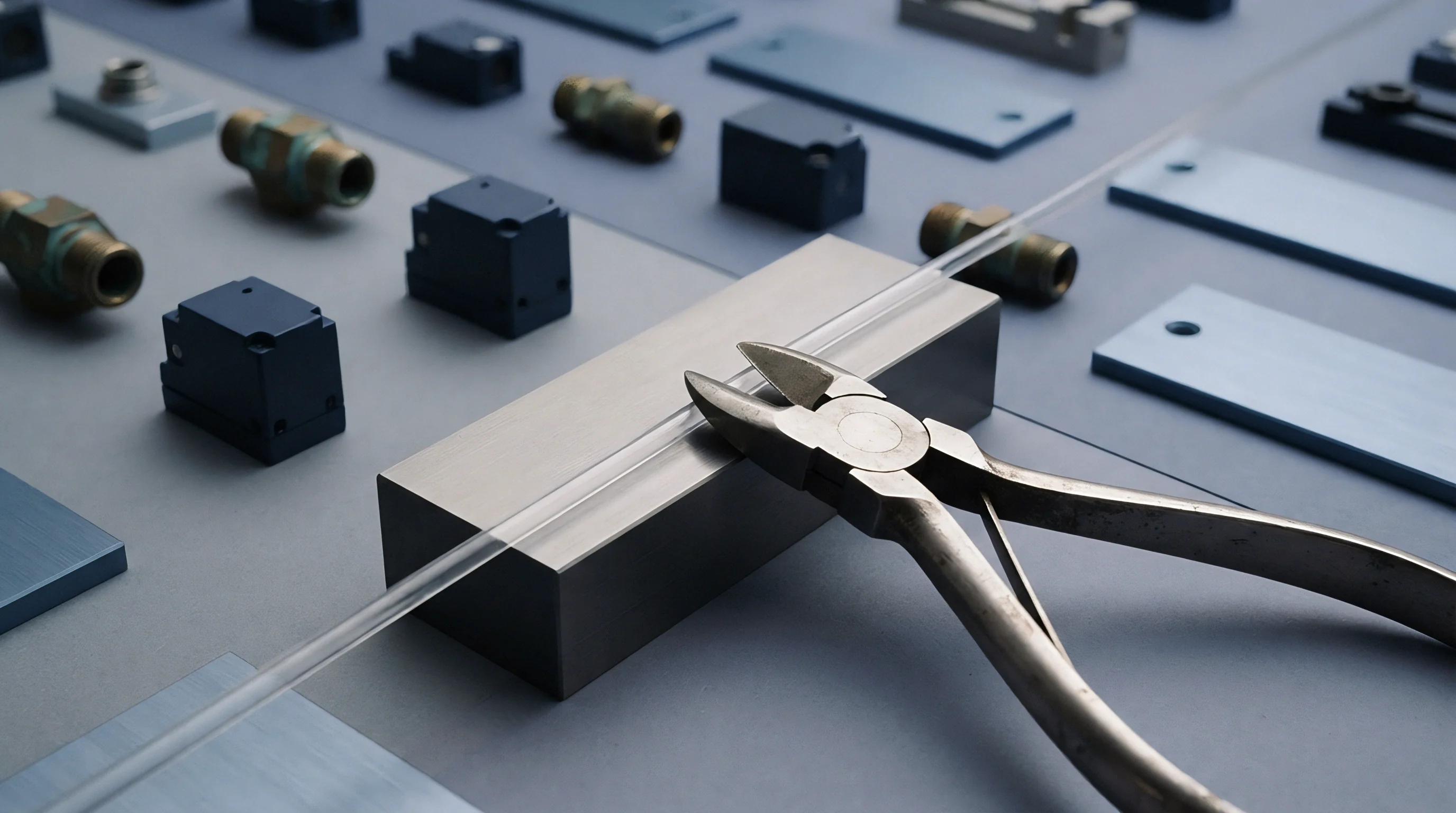

Stress
Parasitic mechanical strain transmitted from protective housings corrupts micromachined silicon diaphragms during operational pressure measurement. Piezoresistive and capacitive MEMS sensing elements detect deflection down to nanometer scales. Unintended structural deformation alters baseline electrical resistance or capacitance, producing output errors indistinguishable from true pressure changes.

Packaging Parasitics in Piezoresistive Diaphragm Assemblies
Pressure transducers utilizing piezoresistive silicon elements exhibit high sensitivity to external dimensional forces. Piezoresistive coefficients in single-crystal silicon depend on crystallographic orientation and local crystal lattice strain. When external mounting torque compresses the sensor die, piezoresistor values drift away from calibrated zero states.
Parasitic forces degrade pressure readings.
Interfacial shear stress between the silicon element and mounting adhesives introduces non-linear offset shifts across operating temperature bands. Epoxy adhesives expand at rates exceeding forty parts per million per Kelvin, creating severe thermal expansion mismatches against silicon at two point six parts per million per Kelvin. As temperature fluctuates, polymer curing strain releases non-uniformly across the chip perimeter.

Mechanical Strain Transmission Paths
External loads enter the sensor body through thread torque, fluid fitting connections, and mounting bracket flexure. Thermal expansion divergence between silicon dies and metallic housings compounds these mechanical vectors. Stainless steel housings expand at rates exceeding sixteen parts per million per Kelvin.
Direct attachment of silicon to metal yields thermal shear stresses exceeding die fracture thresholds under wide temperature excursions. Temperature shifts alter mechanical zero.
Left unmitigated, mounting strain converts structural housing motion directly into pressure measurement drift. Industrial applications subject sensors to ambient temperature sweeps from minus forty degrees Celsius to one hundred twenty-five degrees Celsius. Uninsulated pressure diaphragms experience localized thermal gradients during fluid transients, accelerating non-repeatable zero drift.
Failure to isolate the active diaphragm from packaging shear forces results in calibration loss before completing initial service cycles.

Substrate
Borosilicate glass serves as an intermediate thermal buffer between raw silicon die and metal sensor housings. Placing a high-purity glass mount between the silicon diaphragm and the header isolates piezoresistive elements from mounting torque. Glass pedestals absorb external strain.

Borosilicate Composition and Thermal Matching
Matching thermal expansion coefficients between silicon and support structures minimizes interfacial shear strain. Corning Pyrex 7740 and Schott Borofloat 33 offer thermal expansion curves that closely match single-crystal silicon from minus fifty degrees Celsius up to three hundred degrees Celsius. Chemical formulation determines thermal expansion trajectories.
Thicker glass pedestals reduce package-induced deformation at the cost of assembly height and thermal response rate.
Glass matrices containing roughly eighty-one percent silica, thirteen percent boric oxide, and four percent sodium oxide maintain structural stability across extreme operational envelopes. Alkali metal oxide content supplies mobile sodium ions necessary for electrostatic processing while governing high-temperature electrical resistivity. Thermal matching prevents interface failure.

Technical Selection Parameters
Evaluating candidate materials demands precise measurement of ionic conductivity at high processing temperatures. Electrical resistivity decreases rapidly above two hundred degrees Celsius, allowing sodium ion drift under applied electric fields.
- Thermal Expansion Coefficient Match requires alignment within zero point two parts per million per Kelvin across the full temperature range to prevent interfacial shear.
- Sodium Oxide Content provides mobile alkali ions for field-assisted bonding while keeping dielectric breakdown strength above fifteen kilovolts per millimeter.
- Surface Roughness Peak Height stays below five nanometers root-mean-square to eliminate microscopic void spaces during glass-to-silicon contact.
- Internal Void Density demands inspection under optical polarimetry to verify freedom from bubbles that disrupt stress redistribution.
| Material Designation | CTE at 20°C (10^-6 / K) | CTE at 300°C (10^-6 / K) | Na2O Weight Content (%) | Resistivity at 250°C (Ohm cm) |
|---|---|---|---|---|
| Single-Crystal Silicon | 2.56 | 3.25 | 0.00 | 1.00 x 10^3 |
| Pyrex 7740 Borosilicate | 3.25 | 3.28 | 4.00 | 1.00 x 10^8 |
| Borofloat 33 | 3.25 | 3.25 | 4.00 | 1.20 x 10^8 |
| SD-2 Anodic Glass | 3.10 | 3.15 | 5.50 | 8.00 x 10^6 |
Suppliers frequently state that glass expansion variances under two percent introduce negligible zero drift across standard industrial temperature ranges.


Bonding
Field-assisted joining creates atomic-level sealing between polished glass and single-crystal silicon surfaces. The process unites substrate surfaces without organic adhesives or metallic intermediate layers. Sodium ions migrate under voltage.
Depletion zones form high fields.

Interface Field Mechanics and Chemical Kinetics
Applying high direct-current potential across glass and silicon at four hundred degrees Celsius drives positive sodium ions away from the interface toward the negative cathode. Depleted region formation creates an intense electrostatic field across the microscopic gap between silicon and glass. Field strengths reaching ten million volts per centimeter pull the polished surfaces into intimate atomic contact.
ISO IEC 17025 Section 7.8.2 specifies that calibration records retain raw zero-offset deviation values recorded before and after thermal stress screening, transforming unverified drift claims into auditable traceability metrics.
At elevated temperatures, oxygen ions within the glass matrix migrate across the contact interface under electrostatic attractive forces. Oxygen reacts with surface silicon atoms, producing a chemical layer of silicon dioxide spanning the physical boundary. Anodic bonds yield Hermetic joints.
The resulting joint exhibits mechanical tensile strength exceeding twenty megapascals, transferring structural loads smoothly without creep.

Validation Routines for Joint Integrity
Verifying mechanical strength and joint integrity requires structured evaluation routines.
- Position cleaned glass and silicon wafers in alignment tooling inside the vacuum chamber.
- Evacuate the chamber to a pressure below one millibar to prevent gas trapping in sealed cavities.
- Ramp assembly temperature to four hundred degrees Celsius using uniform radiant heating elements.
- Apply eight hundred volts direct current across the wafer stack for twelve minutes.
- Monitor current decay until charge transport drops below five microamperes per square centimeter.
- Cool the bonded stack down to room temperature at a rate under three degrees Celsius per minute.
ISO IEC 17025 compliance requires calibration laboratories to document environmental screening steps, ensuring traceable measurement records for verified packaging batches.


Clamp
Geometrical decoupling structures isolate sensitive piezoresistive diaphragms from assembly torque. Extending the mechanical path between housing contact surfaces and the active sensing region attenuates external bending forces.

What Pedestal Geometry Optimizes Thermal Strain Decoupling?
Increasing the pillar aspect ratio attenuates bending moments transferred from external housings. Tall, narrow glass pedestals absorb lateral shear through elastic compliance rather than transferring displacement into the silicon chip. Geometry controls strain attenuation.
Long pedestals delay thermal response.
At 125 degrees Celsius, thermal expansion divergence between un-decoupled silicon and brass housings generates 18 megapascals of mechanical shear stress across the diaphragm.
Pillar height calculations trade mechanical strain isolation against thermal resistance and fluid cavity volume. A square glass pedestal with a four-to-one height-to-width ratio reduces housing strain transfer by ninety-four percent compared to direct die mounting. The increased glass volume adds mechanical impedance, dampening high-frequency acoustic shock waves traversing the fluid medium.

Housing Isolation and Mechanical Interfacing
Floating mount architectures support the glass pedestal within elastomer gaskets or metallic diaphragms. Silicone gel encapsulation protects internal wire bonds while transferring hydrostatic pressure cleanly to the sensing surface. Decoupled mounts protect pressure sensors across fluid delivery networks.
Anodic glass mounts featuring central through-holes allow differential and gauge pressure routing directly to the underside of the sensing diaphragm. Glass chemistry resists corrosive chemical media, protecting external reference ports against oxidative decay. Dimensional stability of borosilicate glass maintains fixed reference cavity volumes across years of continuous pressure cycling.
Increasing pedestal height improves mechanical isolation up to the point where structural vibration modes match the application resonance profile.


Hysteresis
Reversible and irreversible zero shifts occur when thermal cycling introduces micro-yield events in sensor joints. Piezoresistive diaphragm networks register internal strain variations as span shift and baseline drift.

Thermal Shift and Micro-Yield Mechanisms
Thermal cycling between minus forty degrees Celsius and one hundred twenty-five degrees Celsius exposes elastic mismatches. Micro-yield events in adhesive layers, solder preforms, or glass interfaces release stored strain non-linearly. Thermal cycles induce micro-yield.
Sodium ion drift inside the glass matrix under high humidity causes long-term zero-point drift in high-temperature installations.
Microscopic plastic deformation changes piezoresistor balance at zero differential pressure. Anodically bonded glass mounts store energy elastically, returning to origin state after thermal transients resolve. Eliminating organic mounting glues removes viscoelastic relaxation behaviors responsible for long-term calibration drift.

Comparative Drift Benchmarks
Long-term laboratory testing compares structural stability across distinct mounting configurations. Uncalibrated drift increases field risk. Calibration frequency scales with tolerance.
- Direct Epoxy Die Mounts exhibit zero offset drift up to zero point eight percent of full scale after one thousand thermal cycles.
- Soft Silicone Gel Encapsulation limits housing stress transfer but leaves the die vulnerable to swelling under solvent absorption.
- Anodic Glass Pedestals maintain zero drift within zero point zero five percent full scale across identical cycling conditions.
- Double-Pedestal Decoupled Stacks isolate top and bottom die faces, holding total hysteresis below zero point zero two percent full scale.
| Mounting Architecture | Thermal Zero Shift (% FS / 100 K) | Pressure Hysteresis (% FS) | Long-Term Drift (% FS / Year) | Operating Limit (°C) |
|---|---|---|---|---|
| Direct Epoxy Header Mount | 0.65 | 0.12 | 0.25 | 105 |
| RTV Silicone Pedestal Seal | 0.35 | 0.08 | 0.15 | 125 |
| Anodic Glass Pedestal Mount | 0.04 | 0.01 | 0.02 | 400 |
| Dual Glass Decoupled Stack | 0.02 | 0.01 | 0.01 | 450 |
Unresolved laboratory measurements leave open whether long-term sodium ion redistribution within the glass depletion layer contributes significantly to zero drift after ten years of continuous DC bias exposure.


Outlay
Manufacturing cost structures reflect wafer-level processing steps, dicing tool wear, and individual calibration requirements. Direct die attachment presents low initial assembly costs but incurs high field failure rates under severe thermal cycling. Yield losses drive unit costs.

Packaging Yield and Process Economics
Processing glass and silicon stacks at wafer scale reduces individual die handling costs. Wafer-level anodic bonding combines hundreds of sensor chips in a single thermal and electrical cycle. Alignment accuracies within two micrometers preserve reference pressure cavities and through-hole port geometries across entire eight-inch wafer surfaces.
Specialized dicing blades equipped with dense diamond matrix grit slice composite glass-silicon wafers without chipping delicate glass pedestal edges. Higher blade wear increases consumable costs per wafer pass by roughly twenty-two percent compared to silicon-only dicing. High yield rates during subsequent thermal screening offset these mechanical tooling expenses.

Grade Economics and Lifecycle Calibration Expenditure
Tighter accuracy specifications increase testing thermal dwell times and rejected unit volumes. Thermal calibration across three temperature points adds bench time and equipment expenses to every shipped sensor. Investing in glass pedestal decoupling reduces thermal compensation complexity during final calibration screening.
Sensors incorporating anodically bonded glass mounts pass zero-shift verification screening at rates exceeding ninety-eight percent. Un-decoupled assemblies yield pass rates below eighty-two percent under industrial grade zero-shift tolerances. The initial capital investment in anodic glass bonding infrastructure lowers overall lifecycle costs for high-precision pressure measurement applications.