Pinout Allocation and Bus Pull-Up Selection for Microcontrollers
Pin allocation and pull-up resistor sizing dictate microcontroller bus rise times, noise margins, and layout routing feasibility across operational packaging formats.


Pin
Assigning silicon I/O pads to package terminals sets the physical limits for PCB trace routing, escape density, and channel-to-channel coupling. Most microcontrollers map internal peripherals ~ serial communication blocks, pulse-width modulators, analog-to-digital converters, and timer capture inputs ~ across a shared pool of external package pins. Placing high-speed digital switching lines right next to sensitive analog inputs couples switching noise directly into measurement channels.
Pin allocation therefore requires separating fast clock and bus signals from analog references and crystal oscillator circuits before layout begins.

Peripheral Multiplexing Architecture
Internal matrix registers determine which peripheral engine drives a given package terminal. On current microcontrollers, a single pin can often serve four or more alternate functions through software-configured mux registers. Sticking with default pin assignments during schematic capture frequently forces trace crossovers and extra vias later during routing.
Working through pin multiplexing options early allows engineers to place open-drain serial buses near board perimeters or target headers without crossing other signal paths.
Package geometry dictates the routing strategy. Gull-wing Quad Flat Packages permit simple visual inspection and wide trace fan-outs, while Quad Flat No-Lead packages demand tighter pad clearances and dedicated thermal pad grounding. Wafer-Level Chip-Scale Packages remove lead-frame inductance altogether, though routing out of them requires fine-pitch HDI microvias.
Picking a package means trading footprint area against fabrication tolerances and the cost of extra PCB layers.
| Package Format | Lead Pitch (mm) | Package Parasitic Capacitance (pF) | Trace Escape Layers | Reflow Solder Yield (%) |
|---|---|---|---|---|
| LQFP-48 | 0.50 | 1.2 to 1.8 | 2 | 99.85 |
| QFN-32 | 0.50 | 0.6 to 1.1 | 2 | 99.70 |
| WLCSP-25 | 0.40 | 0.2 to 0.5 | 4 (HDI) | 99.20 |
| BGA-64 | 0.80 | 0.4 to 0.8 | 4 | 99.50 |
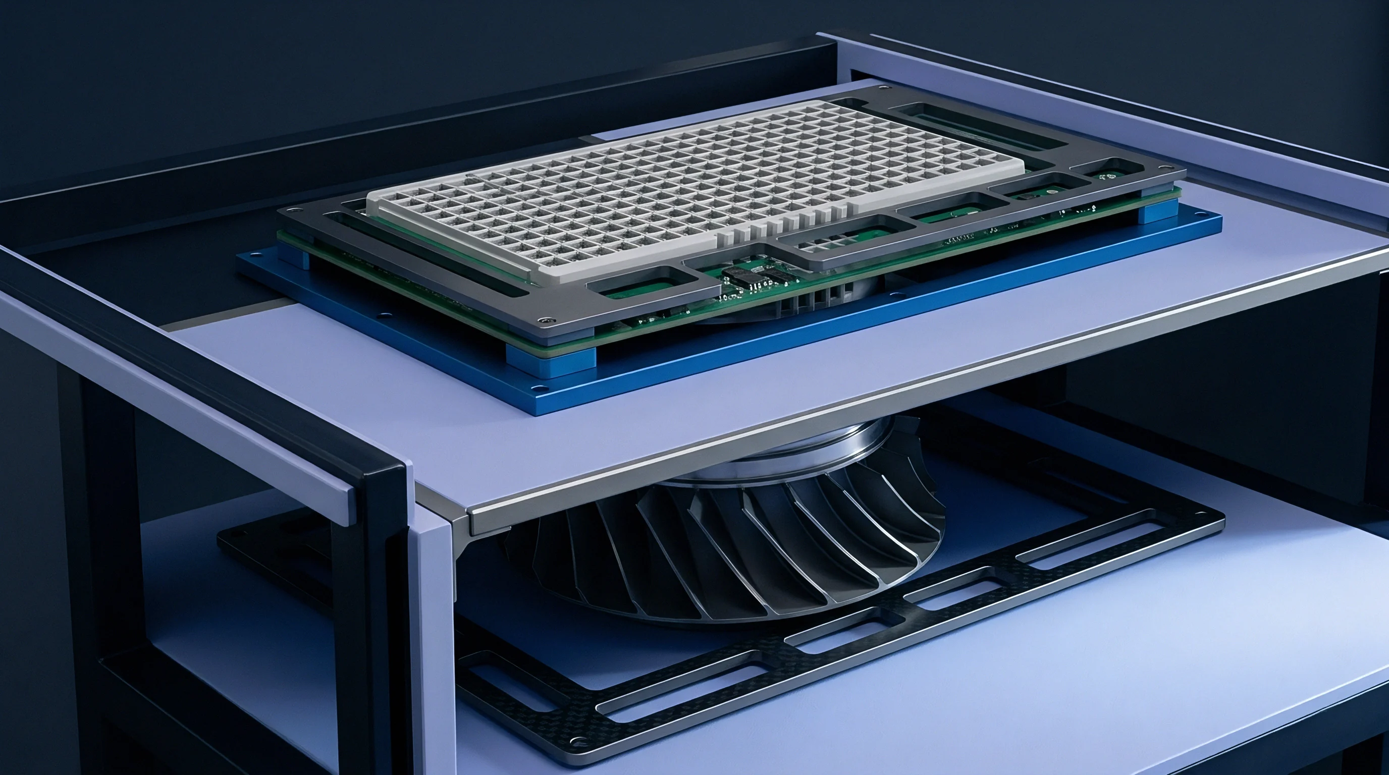
Package Terminals and Spatial Isolation
Physical separation between traces remains the simplest defense against mutual inductance and capacitive crosstalk. Routing a fast serial clock next to a high-impedance analog trace couples edge transients directly into measurement circuitry. Separating open-drain lines with grounded package pins ~ or even unassigned GPIOs tied low ~ provides effective isolation between sensitive domains.
In addition, flooding the board perimeter with continuous ground copper keeps return loops short and helps contain stray fields.
The exposed center pad on bottom-terminated packages provides both heat sinking and a low-impedance RF ground. Stitching this pad to internal ground planes with a tight array of plated through-vias suppresses ground bounce when multiple outputs toggle together. If pin layout ignores return paths and physical isolation, the resulting ground shifts and radiated harmonics frequently cause timing dropouts or fail EMC certification.


Capacitance
Parasitic capacitance on open-drain buses rounds off pulse edges, lengthening rise times and chewing into noise margins. Every trace segment, connector pin, component package lead, and solder pad adds capacitance to the line. Once total bus capacitance exceeds the protocol ceiling, rising edges cannot reach the logic-high threshold before the next clock edge.
Calculating these parasitic contributions during layout prevents intermittent communication issues later on the bench.
Parasitic Sources across Printed Traces
Copper traces add capacitance based on their length, width, and spacing to reference planes. For standard surface microstrip on an FR-4 board, capacitance depends on substrate dielectric constant, copper thickness, and height above the nearest reference layer. Typical 50-ohm microstrip geometry contributes roughly 1.2 to 1.8 pF per inch.
At each node, a microcontroller I/O pin adds roughly 5 to 10 pF, and attached slave IC pins contribute another 5 to 8 pF each.
Standard I2C bus specifications establish a maximum line load of 400 pF for operation up to 400 kHz.
This accumulated capacitance directly slows the rising edge, because the pull-up resistor alone supplies the current needed to charge the line. Falling edges are fast because the driver’s internal low-side MOSFET actively pulls the bus down to ground, but the rising transition follows an RC exponential curve. When capacitance runs high, the slow slope causes timing jitter, clipped ACK bits, and framing errors during Fast-mode transfers.

Bus Loading Dynamics
Checking bus margins involves totaling the individual capacitive contributors across the net. The standard layout audit follows these steps:
- Measure trace length in inches from the microcontroller pin out to the farthest peripheral transceiver.
- Multiply that length by the board’s calculated unit capacitance per inch from the stackup data.
- Add the input pin capacitance specified in the datasheets for the master and each attached slave IC.
- Include stray capacitance introduced by ESD protection diodes, connectors, and test points along the run.
- Check the resulting total against the maximum load permitted by the bus specification at the target clock rate.
Running an open-drain line past its capacitance budget invites intermittent dropouts as temperatures shift or rail voltages sag. When field failures trace back to excessive bus loading rather than defective silicon, claims fall outside component warranty coverage.
Resistor
Pull-up resistor sizing is a compromise between rise-time requirements and output driver current limits. Open-drain buses like I2C and 1-Wire rely entirely on these resistors to pull the line high once drivers release the bus. If the resistance is too high, the rising edge drags, violating setup and hold timing.
If it is too low, drivers must sink excessive current to hold the line down, which elevates V_OL and risks thermal stress on output stages.

Rise Time Calculations and Current Sinking
The upper limit on pull-up resistance is set by total bus capacitance and the protocol’s rise-time ceiling. In I2C Fast Mode running at 400 kHz, the rise time cannot exceed 300 ns. Because the standard measures rise time between 30 percent and 70 percent of VDD, the RC exponential curve yields a constant multiplier of 0.8473.
The formula for maximum resistance is:
R_max = t_r / (0.8473 C_bus)
For example, with a calculated bus capacitance of 150 pF and a target rise time of 300 ns, R_max works out to 300e-9 / (0.8473 150e-12), or roughly 2360 ohms. In practice, this points to a standard E96 resistor of 2.32 kΩ, or 2.2 kΩ from the E24 series.
The lower limit on resistance protects drivers from overcurrent and ensures the low level stays within specification. Drivers must be able to sink the pull-up current without their output voltage rising past V_OL, which is typically specified as 0.4 V at 3 mA. The minimum pull-up value is calculated as:
R_min = (V_DD – V_OL) / I_OL
On a 3.3 V rail with V_OL rated at 0.4 V and I_OL at 3 mA, R_min equals (3.3 – 0.4) / 0.003, or 966.7 ohms. The chosen resistor must fall between this lower threshold and R_max.
Stronger bus pull-ups decrease rise times at the expense of elevated current drain during active low signal states.
Which Bus Pull up Sizing Prevents Bus Degradation?
Choosing a workable value means trading power consumption against edge speed across the full operating environment. In battery-powered gear, higher resistances cut current draw whenever the bus is pulled low. Yet surface contamination, flux residues, and ambient humidity can introduce leakage paths that distort weak pull-up levels over time.
Standard E24 values such as 2.2 kΩ or 4.7 kΩ generally provide enough noise immunity without imposing an excessive current penalty.
Mismatched pull-up resistors generally fail in predictable ways:
- Bus Hangs During Slave Acknowledgment occurs when pull-up resistance is too high for the bus to recover to a valid high level before the next clock pulse.
- Output Driver Overheating results when an undersized resistor forces the driver’s low-side MOSFET to sink currents beyond its thermal rating.
- Logic Threshold Violations happen when excessive pull-up current pushes the low-level output voltage above the receiver’s V_IL threshold.
- Spurious Clock Edge Generation arises when a slow-rising edge lingers in the switching threshold region long enough for ambient noise to trigger double clocking.
Balancing edge speed against driver sink capacity keeps the bus within specification over thermal swings and supply variations.
Crosstalk
Fast edges on adjacent traces readily couple into open-drain lines whenever the bus is floating high. Mutual capacitance and inductance transfer energy from fast aggressors directly into quiet victim nets. Running an unshielded I2C line parallel to a high-speed SPI clock, for instance, frequently introduces glitches that cause false clock pulses or corrupt data bytes.
Preventing this coupling requires deliberate trace spacing and layer management.

Trace Spacing and Differential Coupling
Separation distance dominates coupling behavior. The standard 3W layout rule calls for a center-to-center distance equal to three times the trace width. Opening clearance to 3W cuts mutual coupling by roughly seventy percent compared to running traces at minimum manufacturing spacing.
Where board space permits, placing a continuous, grounded guard trace between signal lines establishes a direct return path that shunts capacitive coupling to ground.
| Mitigation Strategy | Minimum Trace Spacing | Coupling Attenuation (dB) | Board Area Overhead (%) | Required PCB Layers |
|---|---|---|---|---|
| Standard Spacing (1W) | 0.127 mm | -6 | 0 | 2 |
| Expanded Spacing (3W) | 0.381 mm | -14 | 15 | 2 |
| Coplanar Guard Traces | 0.254 mm | -22 | 30 | 2 |
| Orthogonal Layer Routing | 0.127 mm | -30 | 5 | 4 |

IO Bank Isolation and Supply Decoupling
Microcontrollers group pins into discrete I/O power domains. Driving heavy capacitive loads or fast buses from one bank can cause local rail sag and internal ground bounce on that domain. Placing ceramic bypass capacitors right at each VDD and VDDA pin keeps switching transients off the supply rails.
Splitting noisy digital peripherals and analog circuits into separate I/O banks further isolates sensitive nodes from supply rail noise.
IPC-2221A Section 6.4.3 mandates a minimum 3W center-to-center conductor spacing to limit mutual capacitive coupling below negative twelve decibels.
When dense board areas leave no room for 3W spacing on the same layer, changing routing direction between adjacent layers helps. Orthogonal routing on alternating layers eliminates long parallel runs and holds inductive coupling to a minimum. Interleaving solid reference planes between routing layers confines return currents and shields open-drain lines from fast digital nets.
What layout alterations maintain signal integrity when high-density BGA fan-outs prevent minimum 3W trace clearances?


Bringup
Checking bus waveforms on an oscilloscope during initial board bring-up uncovers analog defects that logic analyzers routinely mask. A logic analyzer can decode frames without error even when edge rates are marginal or ground bounce approaches threshold limits. Scope captures show actual rise and fall times, undershoot, and rail margins under real bus traffic.
Viewing the analog waveform directly confirms whether the chosen pull-up resistance and routing geometry work together as intended.
Bench Oscilloscope Inspection
Probing open-drain nets requires low-capacitance active probes; standard passive probes distort the very rise times being measured. A common 10x passive probe adds 10 to 15 pF right at the test point, which can represent ten percent of the entire bus budget. Active FET probes load the line with less than 1 pF, preserving real edge dynamics.
Rise times are measured from 10 percent to 90 percent of VDD to evaluate compliance against protocol limits.
| Operating Voltage (V) | Bus Speed Mode | Max Bus Capacitance (pF) | Recommended Pull-Up (kΩ) | Nominal Rise Time (ns) |
|---|---|---|---|---|
| 1.8 | Standard (100 kHz) | 400 | 2.2 | 740 |
| 1.8 | Fast (400 kHz) | 200 | 1.0 | 170 |
| 3.3 | Standard (100 kHz) | 400 | 4.7 | 880 |
| 3.3 | Fast (400 kHz) | 200 | 2.2 | 370 |
| 3.3 | Fast Plus (1 MHz) | 150 | 1.0 | 125 |
| 5.0 | Standard (100 kHz) | 400 | 10.0 | 950 |
| 5.0 | Fast (400 kHz) | 200 | 3.3 | 280 |

Firmware Configuration of Drive Strengths
Most GPIO controllers include configuration registers for driver impedance, slew rate, and internal bias resistors. Dialing output drive down from 20 mA to 4 mA softens the falling edge and dampens ringing on longer traces without compromising bus timing. Internal pull-ups, which typically span 20 kΩ to 50 kΩ, should be switched off whenever precision external resistors are fitted to manage bus timing.
Bring-up validation requires measuring several core electrical parameters against design targets:
- Voltage Margin Verification confirms that V_OL stays below 0.4 V and V_OH clears 0.7 VDD under full bus loading.
- Rise Time Compliance Check confirms that edge transitions stay within the protocol’s minimum and maximum rise-time limits in each configured speed mode.
- Transient Noise Auditing measures peak ringing and coupled noise spikes on idle lines while adjacent bus pins switch simultaneously.
- Thermal Drift Monitoring tracks pull-up value shifts and driver saturation voltages across the target temperature range in an environmental chamber.
Internal microcontroller pull-up resistors present high nominal tolerances ranging between twenty and fifty percent.
Under IPC-A-610 Class 3 criteria, any solder joint showing incomplete wetting or surface cracks after thermal shock verification fails inspection.

Valuation
Total bill of materials cost across production runs reflects the trade-off between silicon integration and discrete passive networks. Microcontroller package choice sets the floor for silicon cost, pin availability, and routing complexity. Specifying a package with unused pins inflates piece price and can force extra routing layers.
Conversely, choosing too small a package often requires offloading signals to external multiplexers or I/O expanders, adding discrete parts and pick-and-place cycles.

Discrete Resistor Arrays versus Internal Microcontroller Pull-Ups
Internal programmable pull-ups save board space and eliminate SMD placements. But with loose tolerances spanning 20 kΩ to 50 kΩ, their practical use is limited to static strapping pins or slow inputs. Fast serial buses need discrete 1 percent thin- or thick-film resistors to hit predictable rise times across production tolerances.
In production volume, discrete 0402 or 0603 resistors cost a fraction of a cent each. Four-element isolated resistor arrays cut down placement counts and feeder slots during SMD assembly, lowering insertion costs. Designing pads that accept both single discrete chips and quad-resistor packages provides sourcing options during supply pinches.

Package Variants and Total Assembly Expense
Unit cost differs substantially across package variants for the same underlying silicon. A 48-pin LQFP offers lower base part cost and straightforward visual inspection compared to a 25-ball WLCSP. Yet the ultra-compact WLCSP requires high-density interconnect board fabrication with laser-drilled microvias, which can raise bare-board costs by thirty to sixty percent.
Landed cost analysis weighs raw silicon pricing, passive component costs, pick-and-place fees, and board layer counts together. Below five thousand units, leaded packages paired with standard discrete passives keep tooling low and avoid specialized inspection setups. Past one hundred thousand units, the board space saved by chip-scale packaging and resistor arrays overcomes the premium for high-density board fabrication, driving total unit cost down.