Non Ferrous Inductive Target Thickness Selection Principles for Precision Displacement Sensors
Target thickness for non-ferrous displacement sensors must equal at least three skin depths at the probe operating frequency to eliminate measurement errors.


Sheet
An eddy current probe driven at 1 megahertz interrogating an aluminum 6061 target requires a minimum material thickness of 300 micrometers before the measured impedance decouples from the dimension of the target itself. Placing a 100-micrometer foil under that same probe reduces sensor output voltage by 42 percent across a 1.0-millimeter measuring range, introducing a false displacement offset of 180 micrometers into the signal conditioner. The transducer detects boundary penetration rather than true position.
Thin conductive layers fail to confine the alternating electromagnetic field, allowing magnetic flux to bleed into open air or underlying mechanical structures.
Precision displacement measurements rely on complete eddy current containment. High-frequency current circulating through the sensing coil projects an oscillating magnetic field into the target face, inducing counter-acting currents that oppose the incident field, lower coil inductance, and elevate effective resistance. As target thickness drops below the depth where these counter-acting loops form, the return signal loses amplitude and calibration curves established on semi-infinite reference blocks collapse into non-linear transfer functions.
A non-ferrous target must present a minimum thickness equal to three standard skin depths at the operating frequency of the probe to prevent dimensional thickness variations from registering as false displacement.
Operating manuals frequently omit the mathematical boundary where a target transitions from an electrically thin foil to an electrically infinite half-space. Precision displacement sensors operating on inductive or eddy current principles run between 500 kilohertz and 2.5 megahertz. High-frequency units crowd current loops into shallow surface bands, permitting thinner target stock, whereas low-frequency systems throw broader electromagnetic fields that penetrate millimeters into structural alloys.
The physical conductor must absorb the entirety of this field energy to maintain sub-micron repeatability.
Thinner materials exhibit acute sensitivity to batch variations in sheet rolling tolerances. Commercial aluminum shim stock specified at 0.25 millimeters standard thickness carries an allowable rolling variation of plus or minus 10 percent under standard mill specifications. When sensor field penetration extends through the sheet, a 25-micrometer variance in stock thickness produces an immediate three-micrometer calibration shift across identical production assemblies.
Designers isolate the measurement from bulk thickness fluctuations by specifying targets exceeding the three-skin-depth threshold.
Select target thickness from the electrical skin depth calculated at the lowest permissible excitation frequency of the sensor channel.

Decay
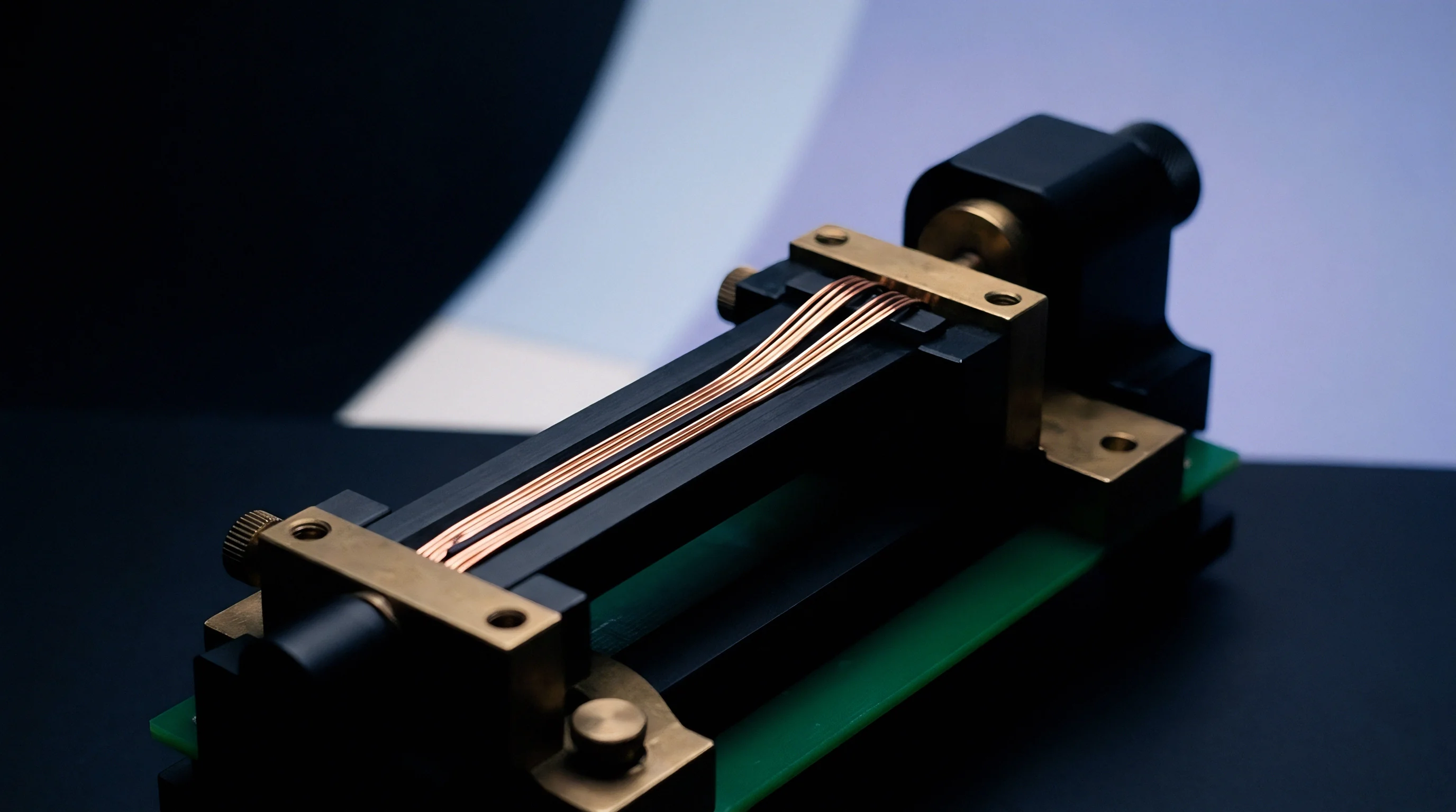
Electromagnetic fields propagating into a conducting half-space lose amplitude through ohmic dissipation. The standard penetration depth, designated as skin depth, defines the plane where current density falls to 36.8 percent of its surface value. Because eddy currents decay exponentially, this attenuation follows the classical relationship governed by excitation frequency, magnetic permeability, and volume electrical conductivity.
Non-ferrous targets share a relative magnetic permeability of unity, isolating conductivity and frequency as the operative variables.
The standard skin depth equation evaluates directly from material properties:
Skin depth equals the square root of electrical resistivity divided by the product of pi, excitation frequency, and magnetic permeability. Expressed through conductivity, skin depth equals the reciprocal of the square root of the product of pi, frequency, magnetic permeability of free space, and target electrical conductivity. At an excitation frequency of 1.0 megahertz, copper exhibits a skin depth of 66 micrometers.
Aluminum 6061 exhibits a skin depth of 102 micrometers. Cartridge brass exhibits a skin depth of 130 micrometers. Grade 5 titanium, possessing substantially higher resistivity, yields a skin depth of 680 micrometers under identical excitation.

Why Do High Excitation Frequencies Permit Thinner Targets?
Sensor drive electronics operating at 2.4 megahertz compress the penetration zone toward the immediate component face, allowing the secondary field to mirror the coil field with minimal volumetric depth. An aluminum target evaluated under a 2.4 megahertz carrier achieves field saturation at 195 micrometers, whereas a 500 kilohertz industrial bridge circuit requires 450 micrometers to establish identical impedance stability.
Energy confinement scales through successive multiples of the calculated skin depth:
- Single skin depth absorption confines 63.2 percent of circulating eddy current density, leaving substantial electromagnetic flux unattenuated across the rear face.
- Two skin depths absorption captures 86.5 percent of total current energy, yet permits measurable sensitivity shifts when backing substrates alter.
- Three skin depths absorption dissipates 95.0 percent of circulating energy, establishing the practical threshold for industrial displacement accuracy.
- Five skin depths absorption attenuates 99.3 percent of the incident field, satisfying laboratory metrology requirements where sub-nanometer stability governs acceptance.
When target thickness falls below two skin depths, the phase relationship between sensor drive voltage and inductive bridge current rotates. Signal conditioning electronics interpret this phase shift as target lift-off, confounding distance changes with target gauge shifts. Inductive bridge circuits balance inductive reactance against resistive loss; thin targets alter that ratio, skewing the calibration polynomials mapped into sensor firmware.
Calibration curves lose mathematical validity when target thickness shifts fall within the active three-skin-depth electromagnetic zone.
Consider an instrument installation specifying a 1.0-millimeter measuring range with a target face positioned at a 500-micrometer nominal standoff. Assume a sensor carrier frequency of 1.0 megahertz and a copper target machined to a thickness of 100 micrometers. The skin depth of copper at this frequency equals 66 micrometers, meaning the physical target represents only 1.5 skin depths.
Unattenuated field energy penetrates the target rear boundary, coupling into mounting brackets or surrounding air. If the target flexes during motion, modulating its rear-air boundary or mechanical fixture proximity, the signal conditioner detects apparent front-face motion without physical translation. The system records electrical noise indistinguishable from mechanical vibration.
The physical interaction leaves open the question of whether multi-frequency excitation circuits can dynamically calculate target thickness variations during active operation without sacrificing signal bandwidth.

Alloy
Electrical conductivity dictates the minimum permissible target dimension across all non-ferrous metals. High-conductivity metals like copper generate tight, shallow current loops that reflect field energy near the outer boundary. Resistive alloys, by contrast, permit the sensor field to propagate deep into the material matrix, mandating heavy section thicknesses to avoid rear boundary transmission errors.
Substituting an alloy without adjusting target thickness alters both sensor sensitivity and linearity.
| Alloy Designation | Conductivity (% IACS) | Resistivity (10^-8 Ohm-m) | Skin Depth (microns) | Minimum Thickness (3x, mm) | Metrology Thickness (5x, mm) |
|---|---|---|---|---|---|
| Copper C10100 (OFHC) | 101.0 | 1.71 | 65.8 | 0.20 | 0.33 |
| Aluminum 1100-H14 | 59.0 | 2.92 | 86.0 | 0.26 | 0.43 |
| Aluminum 6061-T6 | 43.0 | 4.00 | 100.7 | 0.30 | 0.50 |
| Aluminum 7075-T6 | 33.0 | 5.22 | 115.0 | 0.35 | 0.58 |
| Cartridge Brass C26000 | 28.0 | 6.16 | 124.9 | 0.37 | 0.62 |
| Titanium Ti-6Al-4V (Gr5) | 1.0 | 172.0 | 660.0 | 1.98 | 3.30 |
| Austenitic Steel 316L | 2.3 | 74.0 | 432.8 | 1.30 | 2.16 |
Conductivity variations introduce immediate scale shifts. Aluminum 6061-T6 provides an exceptional baseline target material due to structural rigidity, machinability, and uniform electrical traits. Swapping aluminum 6061-T6 for aluminum 7075-T6 reduces conductivity from 43 percent International Annealed Copper Standard to 33 percent, expanding the calculated skin depth from 101 micrometers to 115 micrometers.
A 0.30-millimeter target thickness, completely stable on an aluminum 6061 installation, fails to satisfy the three-skin-depth requirement on aluminum 7075 stock, inducing rear-boundary coupling errors.
Thermal coefficients compound the mechanical thickness requirement. Conductivity decreases as metal temperature rises, driving the skin depth deeper into the material during thermal cycling. Copper shifts electrical resistivity by 0.39 percent per Kelvin.
When an operating enclosure heats from 20 degrees Celsius to 70 degrees Celsius, copper target resistivity rises by 19.5 percent and skin depth expands proportionally by 9.3 percent. A marginal target thickness selected for room-temperature equilibrium permits flux leakage at high operating temperatures.
Machined components exhibit localized microstructural variations. Cold working alters grain boundary dislocation densities, depressing localized electrical conductivity. An unannealed drawn brass sheet exhibits conductivity bands varying up to 4 percent across its surface.
A sensor scanning along a thin drawn section records thickness-coupled conductivity waviness as physical displacement. Thermal stress relief or specifying annealed stock stabilizes the internal resistivity profile.
Specifying high-resistivity metals such as titanium Grade 5 or 316L stainless steel demands massive targets, requiring several millimeters of solid cross-section to isolate the measurement. Lightweight structures utilizing thin titanium shells cannot sustain precision eddy current sensing without bonding secondary high-conductivity target plates to the measurement zones.
Ignoring alloy conductivity dynamics during target selection produces chronic drift that forces extensive structural redesigns after tooling fabrication finishes.

Backing
Electromagnetic fields passing through thin targets intercept whatever substrate supports them. When a thin non-ferrous metal skin rests against a ferromagnetic carrier, the underlying steel draws magnetic flux and sets up two competing physical mechanisms: eddy currents in the thin top layer depress coil inductance, while magnetic permeability in the steel carrier amplifies it. The two responses work in opposition, creating non-monotonic voltage-to-distance relationships.
Substrate interference generates severe output anomalies. An inductive displacement probe calibrated for pure aluminum exhibits inverted sensitivity curves when tracking a 50-micrometer aluminum foil glued to a structural carbon steel beam. At long standoffs, the low-frequency boundary of the sensor field penetrates directly to the steel, pulling the oscillator frequency down.
At short standoffs, surface eddy currents in the aluminum dominate, driving the oscillator frequency up. The slope of the demodulated output inverts midway through the measurement span.
| Backing Substrate | Substrate Permeability (ur) | Substrate Conductivity (% IACS) | Signal Deviation at 0.5 mm Standoff | Linearity Deviation (% Full Scale) |
|---|---|---|---|---|
| Air (Free Space) | 1.0 | 0.0 | Baseline Calibration | 0.12 |
| Structural Steel A36 | 100 to 400 | 10.0 | +18.4% Output Offset | 4.85 |
| Ferritic Stainless 430 | 300 to 600 | 2.8 | +22.1% Output Offset | 6.20 |
| Austenitic Steel 304 | 1.02 | 2.4 | -3.6% Output Offset | 0.85 |
| Copper C11000 Plate | 1.0 | 100.0 | -12.2% Output Offset | 2.40 |
While backing metals distort returning inductance, non-metallic substrates introduce their own distinct failure modes. Air gaps behind thin foil targets allow structural resonance: acoustic waves or machine vibration cause unbonded foils to drum against backing blocks, altering the instantaneous foil-to-probe gap independently of structural motion. Adhesive layers bonding thin targets introduce thermal expansion artifacts as well, since epoxy adhesives expand at rates between 40 and 80 parts per million per Kelvin, widening the gap between target and substrate and driving baseline drift.
A standard mill report stating nominal target thickness provides zero protection against substrate interference when mechanical tolerances run negative.
The progression of substrate coupling follows discrete mechanical steps:
- Field emergence begins at the rear boundary when target thickness drops below three skin depths.
- Substrate eddy generation develops as transmitted magnetic flux induces secondary circulating currents within conductive mounting structures.
- Flux concentration occurs if backing materials contain ferromagnetic iron, altering probe coil self-inductance and suppressing the bridge carrier voltage.
- Bridge imbalance distorts the linearization tables stored inside the receiver electronics, producing unrecoverable measurement errors.
Although air gaps yield zero reflection and eliminate magnetic return paths, field energy still radiates uselessly through the target, depressing the quality factor of the probe resonant tank. The oscillator loses calibration stability. To secure reproducible displacement readings, the non-ferrous sheet must serve as an absolute electromagnetic shield, extinguishing field energy prior to the substrate interface.
Technicians often assume any metallic sheet provides an adequate displacement target if it looks flat and covers the diameter of the probe coil.
Stock
Procuring raw material for precision target faces requires explicit dimensional and metallurgical controls. Mill run sheets purchased without precision rolling callouts carry thickness variations that consume substantial portions of a precision measurement budget. Foil and thin strip stock produced under ASTM B209 for aluminum or ASTM B152 for copper permit gauge variations exceeding 10 percent on thin gauges.
The incoming inspection protocol verifies both absolute thickness and local flatness.
Design documentation must define target requirements through functional engineering parameters:
- Target alloy specification defines the metallurgical temper and chemical composition, establishing the exact electrical conductivity baseline.
- Minimum target thickness establishes the finished cross-section after machining, maintaining the required skin depth threshold at the lowest operating frequency.
- Surface roughness limits restrict peak-to-valley heights to less than 0.4 micrometers Ra, preventing surface texture from modulating the high-frequency current path.
- Backing material constraints mandate non-conductive bonding layers or specify identical substrate alloys when target inserts reside within larger mechanical housings.
Machining thin stock introduces severe residual stresses. Single-point fly cutting of aluminum target blanks removes surface layers non-uniformly, releasing internal rolling stresses and warping the target face into a convex or concave geometry. Non-planar targets distort the symmetry of the electromagnetic field, destroying measurement linearity across the measuring range.
Vacuum chucking during finish grinding, accompanied by cryogenic stress relief, preserves planar geometry across thin cross-sections.
Target thickness selection interacts directly with mechanical diameter: target diameter must equal at least three times the outer diameter of the sensor coil to eliminate perimeter edge effects. When thickness is marginal, edge effects propagate inward toward the center, compressing the linear measuring range. Providing an expansive, thick target surface eliminates field fringing and provides an ideal half-space for eddy current circulation.
Procurement documents referencing standard commercial strip tolerances without specifying minimum electrical skin depth boundaries fail incoming quality audits once target thinning induces channel recalibration rejections.