Quantifying Mechanical Intermetallic Degradation and Cash Allocation in Component Obsolescence Mitigation
Mitigating component obsolescence requires balancing upfront redesign costs against the physical reliability risks of intermetallic solder degradation.


Growth
Solid-state diffusion transforms ductile metallurgical bonds into brittle stoichiometric phases over extended operating lifecycles. When tin-based solder alloys interface with bare or plated copper traces on a printed circuit board, copper-tin intermetallic compounds form instantly during reflow and continue to evolve isothermally at ambient and elevated equipment temperatures. The initial reaction produces scallop-shaped crystals of Cu6Sn5 at the liquid-solid boundary.
Subsequent thermal aging promotes the consumption of adjacent copper, converting the interfacial zone into planar Cu3Sn layers that exhibit lower fracture toughness, reduced electrical conductivity, and an increased susceptibility to microvoid coalescing.
The rate of solid-state intermetallic layer thickening follows parabolic diffusion kinetics, governed by the classical Arrhenius relationship where the intermetallic thickness layer grows as a function of the diffusion coefficient and thermal dwell time. For SAC305 (96.5Sn-3.0Ag-0.5Cu) solders operating across industrial temperatures of 55 degrees Celsius to 85 degrees Celsius, the total compound thickness expands from an as-soldered baseline of 0.8 micrometers plus or minus 0.2 micrometers to values exceeding 4.5 micrometers over a decade of continuous run-time. Cu3Sn development accelerates at temperatures above 60 degrees Celsius, exhibiting an activation energy of approximately 0.85 electron-volts to 1.05 electron-volts depending on trace grain boundary orientations.
Kirkendall void density correlates directly with the thermal exposure duration of copper-tin interfaces operating above fifty-five degrees Celsius.
Intermetallic growth alters the mechanical stress distribution within ball grid array joints and quad-flat no-lead perimeter lands. As the combined Cu6Sn5 and Cu3Sn intermetallic band consumes the bulk solder above it, the compliant volume available to absorb shear displacement shrinks. Thermal expansion mismatches between FR-4 laminates (coefficient of thermal expansion 14 to 17 parts per million per Kelvin) and silicon dies mounted in low-profile fine-pitch packages (coefficient of thermal expansion 2.6 to 3.5 parts per million per Kelvin) impart cyclic plastic strain into the joint during diurnal thermal cycling.
Cracks nucleate along the boundary between the Cu3Sn intermetallic compound and the copper land, propagating under low-cycle mechanical fatigue until total circuit detachment occurs.
Kinetics of Intermetallic Phase Evolution
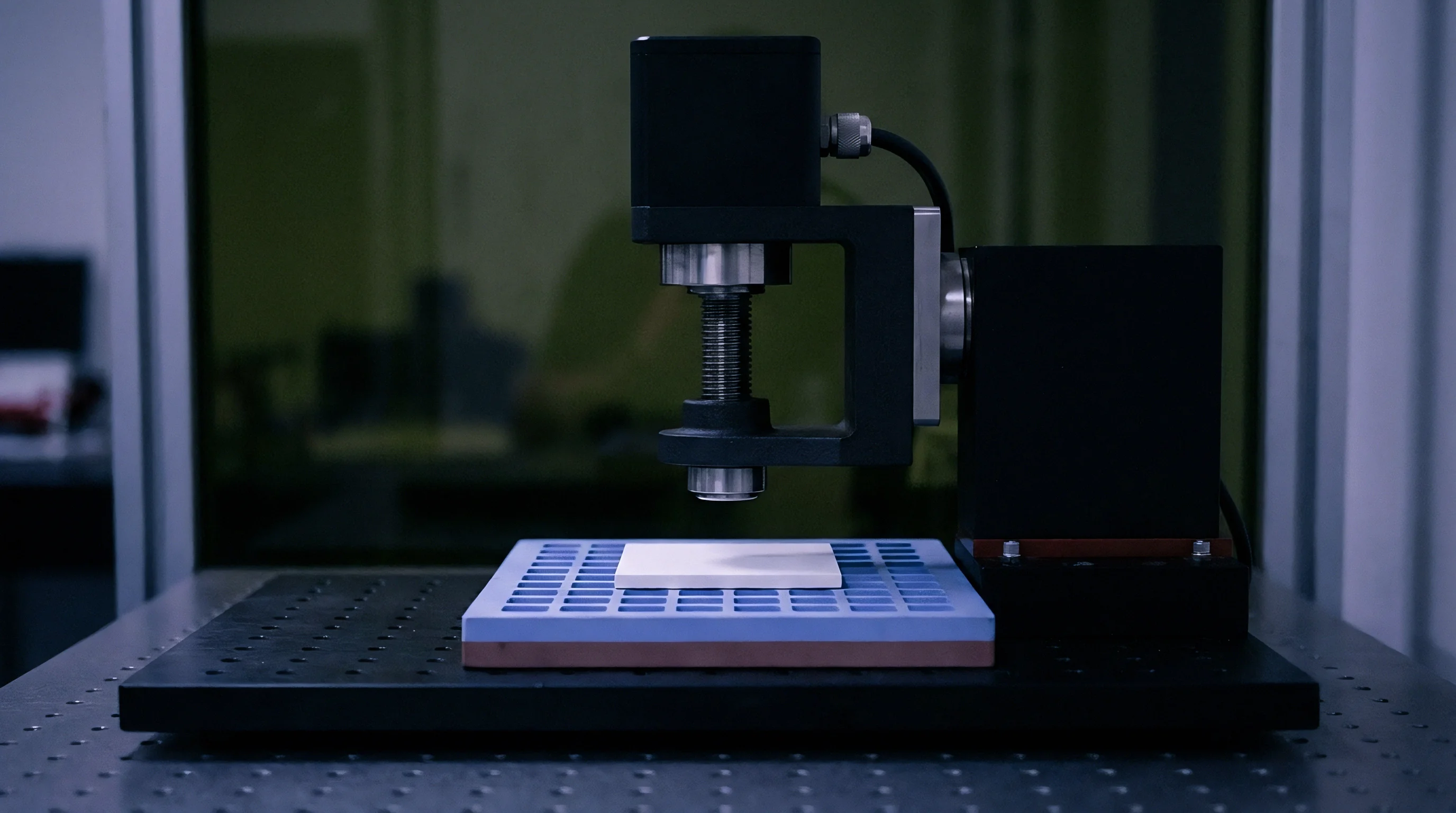
Atomic transport mechanisms dictate phase formation sequences at soldered interfaces. During initial reflow cooling, Cu6Sn5 forms rapidly at 217 degrees Celsius to 220 degrees Celsius. When operational heat sinks fail or enclosed industrial field enclosures sustain unventilated internal temperatures, tin atoms migrate toward the bulk copper substrate while copper atoms diffuse into the intermetallic matrix.
This bi-directional migration displays unequal diffusion fluxes, establishing vacancies at the copper-Cu3Sn interface. The vacancies coalesce into structural Kirkendall microvoids, weakening interfacial shear strength under dynamic shock loads.
Calculations for intermetallic thickness growth utilize the standard equation:
X(t) = X0 + square_root(D t)
Here, X0 represents the initial intermetallic thickness post-reflow, t represents the operating or dwell duration in seconds, and D represents the effective interdiffusion coefficient expressed as:
D = D0 exp(-Q / (R T))
In this formulation, D0 defines the frequency factor, Q defines the activation energy in joules per mole, R represents the universal gas constant (8.314 joules per mole-kelvin), and T denotes absolute temperature in kelvin. Empirical evaluations across Sn-Ag-Cu solders place the apparent activation energy for total intermetallic growth within 65 to 88 kilojoules per mole. Consequently, an operational temperature rise from 50 degrees Celsius to 75 degrees Celsius accelerates intermetallic volume generation by more than 280 percent, drastically reducing product life margins.
Substrate surface finishes directly govern the diffusion barrier properties against copper migration. Electroless nickel immersion gold (ENIG) deposits an intermediary nickel-phosphorus layer of 3.0 to 5.0 micrometers thickness, shifting the primary compound from Cu6Sn5 to Ni3Sn4. While Ni3Sn4 exhibits substantially slower solid-state growth rates than copper-tin intermetallics, phosphorus atoms reject during the nickel-tin reaction to form a fragile, phosphorus-rich Ni3P layer directly beneath the intermetallic compound.
Mechanical shock events then trigger brittle interfacial fracture across this unreacted black-pad interface.
A supplier will occasionally argue that component moisture sensitivity levels have no bearing on intermetallic fatigue once reflow completes cleanly.


Degradation
Dynamic mechanical failures originate at structurally compromised intermetallic layers. While cyclic thermal expansions produce predictable creep-fatigue along solder grain boundaries, sudden mechanical shocks impose high strain rates exceeding 10 to the second power per second, loading the brittle intermetallic interface directly. A nominal SAC305 bulk solder joint exhibits an elastic modulus of 40 to 50 gigapascals and yield strength near 30 megapascals, allowing microscopic plastic deformation to absorb mechanical energy.
By contrast, Cu6Sn5 and Cu3Sn intermetallic compounds display elastic moduli of 110 gigapascals and 132 gigapascals respectively, with negligible plastic yield capability.
Under board-level drop testing conducted per JESD22-B111 specifications, stress concentrates precisely at the corner joints of bottom-terminated packages. The intermetallic-to-bulk-solder boundary experiences maximum principal tensile stress. As Kirkendall voids accumulate along the Cu3Sn interface during thermal storage or sustained operation, the effective load-bearing area diminishes.
Cleavage fractures initiate across these sub-micron void arrays, severing connection lands without plastic deformation in the surrounding bulk solder ball. Component obsolescence issues intersect this physical reality when vintage replacement stock, procured after years of warehouse storage, exhibits advanced pre-existing interdiffusion before installation onto boards.

Mechanical Shock and High-Strain Dynamics
Field installations subject circuit boards to continuous vibrational profiles and sharp acceleration pulses. Package architectures with low standoff heights, such as ultra-thin quad-flat no-lead (UQFN) housings with standoffs under 0.05 millimeters, display increased shear strain compared to ball grid arrays with 0.40 millimeter sphere diameters. Solder joint standoffs dictate the total angular displacement absorbed during printed circuit board bending cycles.
The JEDEC JESD22-B111 standard prescribes board drop conditions utilizing a half-sine shock pulse of 1500 g acceleration amplitude and 0.5 millisecond pulse duration. Under these conditions, the number of cycles to failure drops precipitously as a function of interfacial intermetallic thickness:
- As-soldered intermetallic baseline absorbs 250 to 400 drop cycles prior to electrical disconnection, maintaining clean transgranular bulk solder yielding across the joint core.
- Aged intermetallic layers exceeding two micrometers survive fewer than 90 drop cycles, with failure planes relocating cleanly along the Cu3Sn-to-copper pad interface.
- High-density Kirkendall void arrays induce instantaneous cleavage during the initial 15 shock pulses, demonstrating zero plastic energy dissipation capability within the interconnect region.
Standoff compliance balances board deflection forces. When stiff, leadless surface-mount sensors encounter PCB deflection, the mechanical force routes directly into the corner terminations. Designers often fail to recognize that obsolete sensors sourced through secondary channels may carry aged, pre-oxidized leads or re-balled interconnects with thick, uncontrolled intermetallic seeds created during unsanctioned hot-air rework operations.

Interface Mechanics under Long-Term Storage
Room-temperature aging induces measurable solid-state diffusion over multi-year obsolescence mitigation timelines. Although diffusion coefficients scale down with temperature, components held in warehouse vaults at 25 degrees Celsius for eight to twelve years experience uninterrupted intermetallic expansion. For leadframes plated with pure bright or matte tin over copper without an intermediate nickel barrier, Cu6Sn5 growth proceeds along tin grain boundaries at ambient conditions, consuming approximately 0.2 to 0.5 micrometers of tin plating thickness every five years.
| Interface Metallurgy | Dominant Phase | Activation Energy (eV) | Growth Rate at 70°C (um/hr^0.5) | Elastic Modulus (GPa) |
|---|---|---|---|---|
| SAC305 on Bare Copper | Cu6Sn5 / Cu3Sn | 0.88 | 0.0142 | 115.0 |
| SnPb (63/37) on Bare Copper | Cu6Sn5 | 0.72 | 0.0210 | 108.0 |
| SAC305 on Electroless Ni | Ni3Sn4 | 1.18 | 0.0031 | 135.0 |
| SAC305 on Immersion Silver | Cu6Sn5 | 0.86 | 0.0145 | 112.0 |
Tin whisker initiation represents an adjacent failure mode driven by intermetallic development. The compressive stress generated within matte tin plating by anisotropic grain boundary diffusion of copper into tin forces spontaneous filamentary eruption. Whiskers reaching lengths beyond 50 micrometers present catastrophic bridging hazards across adjacent pins on 0.50 millimeter pitch sensors.
Incorporating a 1.5 to 3.0 micrometer nickel barrier underneath final plating eliminates copper diffusion into the tin layer, arresting compressive stress development and eliminating whisker formation.
Failure to mandate complete metallurgical stripping and re-plating on vintage lot inventory guarantees assembly yield fallouts during downstream mechanical testing.


Allocation
Component obsolescence confronts engineering organizations with conflicting financial and technical trade-offs. When an original component manufacturer issues a Product Discontinuation Notice (PDN), cash allocation must proceed under strict balance sheet constraints. Sourcing practitioners must choose between financing a lifetime buy, redesigning the printed circuit assembly around active silicon, or introducing drop-in package emulators.
Each pathway carries distinct capital requirements, carrying costs, and metallurgical risks that directly affect the total landed cost of sustaining critical electronics systems.
A lifetime buy locks operational working capital into stagnant inventory, requiring upfront non-recurring expenditure for multi-year warehouse storage. Conversely, a printed circuit board redesign demands direct non-recurring engineering (NRE) investment for schematic capture, routing changes, board fabrication, and firmware rework. Firmware costs routinely outstrip hardware layout expenses when the sensor interface changes from an obsolete 5-volt analog ratiometric output to a modern low-power 1.8-volt digital bus like I2C or SPI.
Firmware register map updates, driver qualification, and bus validation can demand eight to sixteen weeks of dedicated engineering time.
A contractual requirement for lot-specific shear testing prevents distributors from fulfilling obsolescence orders with chemically compromised vintage components.
Carrying costs for stored components compound annually through climate-controlled storage leases, nitrogen-purged desiccator maintenance, electrostatic discharge protection compliance, and continuous inventory tracking. Over a seven-to-ten-year lifecycle, cumulative storage overhead routinely adds 20 to 35 percent to the initial purchase price of obsolete silicon. More critically, as stored parts age, their internal wire bonds, die attach adhesives, and external terminal finishes experience the gradual intermetallic degradation detailed above, depressing assembly yields when the parts are finally pulled for production runs years later.

Comparative Capital Allocation Models
Deciding between lifetime component procurement and active product redesign requires clear mathematical evaluation of lifecycle costs. The model evaluates three mitigation pathways across sustained operational windows:
- Lifetime inventory procurement absorbs severe upfront working capital, generates recurring holding fees, and exposes the product line to physical solderability decay during long-term desiccation.
- Printed circuit board redesign demands steep near-term NRE investments for board layout and firmware refactoring while securing commercial component availability for extended lifecycles.
- Pin-compatible interposer daughterboards preserve host PCB designs and eliminate firmware churn, yet introduce dual reflow solder joints that double the total interfacial intermetallic failure points.
The total cost of an obsolescence mitigation pathway (C_total) calculates via the unified model:
C_total = C_procure + C_holding + C_nre + C_qualification + C_failure_risk
C_procure reflects initial component acquisition costs, including inflated spot-market premiums charged by secondary brokers. C_holding comprises physical storage, desiccation, atmospheric nitrogen replenishment, and insurance over the storage interval t. C_nre accounts for board respin engineering hours, prototype fabrication, and firmware development.
C_qualification incorporates environmental stress screening, thermal shock testing, and regulatory certifications (such as FCC, CE, or UL re-filings). C_failure_risk encapsulates scrap rates from un-solderable terminations, assembly yield fallout, and field warranty claims caused by brittle intermetallic fracture.

Whom Does the Sourcing Strategy Protect?
Financial exposure distributes unevenly across corporate silos during obsolescence mitigation programs. Procurement departments frequently optimize for low initial purchase prices by purchasing unverified factory overstock from secondary open-market distributors. This strategy satisfies immediate inventory milestones while transferring severe metallurgical risk onto manufacturing operations.
When aged inventory with thick intermetallic interfaces enters the pick-and-place line, assembly yields plummet due to dewetting, non-wetting, and post-reflow solder joint cracking under automated optical inspection (AOI).
| Mitigation Strategy | Initial NRE ($) | Unit Cost Delta ($) | Storage Cost ($/Yr) | Qualification Fee ($) | Assembly Yield Loss Risk |
|---|---|---|---|---|---|
| Lifetime Buy (Original Silicon) | 0 | +1.20 | 4,800 | 2,500 | 8.5% (Aged Solderability) |
| Full Board Redesign (Modern IC) | 65,000 | -3.40 | 0 | 38,000 | 0.5% (Fresh Production) |
| Interposer Adapter Module | 18,000 | +6.80 | 600 | 12,000 | 4.2% (Double Joint Fatigue) |
| Open-Market Secondary Sourcing | 0 | +18.50 | 1,200 | 14,000 | 14.0% (Counterfeit / Oxidized) |
Engineering managers must calculate the breakeven threshold where non-recurring engineering expenses become more cost-effective than carrying inventory. When an active replacement sensor costs three dollars less than the obsolete component, a 65,000 dollar engineering and qualification effort achieves breakeven at approximately 21,667 production units. For products sustaining high annual run-rates, immediate redesign represents the only financially defensible path.
For low-volume aerospace or medical systems where regulatory re-certification costs reach hundreds of thousands of dollars, lifetime inventory buys remain mandatory despite the severe intermetallic aging vulnerabilities created over time.
The contract buyer must verify whether secondary brokers provide certified dry-packing logs and original manufacturer lot codes before authorizing wire transfers.


Qualification
Physical verification of incoming legacy or long-stored component inventory prevents defective metallurgies from contaminating high-reliability production lines. Standard incoming visual inspection cannot expose subsurface intermetallic evolution or Kirkendall void formation. Sourcing and quality teams must execute rigorous metallurgical test protocols on statistical sample lots drawn from aged inventory prior to releasing the stock to production kitting.
Non-destructive scanning acoustic microscopy (C-SAM) combined with destructive cross-sectional metallography and solderability dip-and-look testing forms the minimum verification baseline.
Cross-sectional preparation demands precision diamond-saw sectioning through critical corner pins, followed by cold mounting in epoxy resin to prevent thermally induced metallurgical alteration during sample preparation. Mechanical polishing with silicon carbide papers down to 0.05 micrometer colloidal silica suspensions reveals clean grain boundaries and interfacial layers. Subsequent chemical etching using an ammonium persulfate or light nitric-acid swab selectively dissolves the bulk tin-lead or SAC alloy, delineating the intermetallic boundary for scanning electron microscopy (SEM) and energy-dispersive X-ray spectroscopy (EDS) analysis.

Mechanical Shear Verification Protocols
Solder ball and lead shear testing provides direct quantitative measurement of interfacial strength, operating per JEDEC JESD22-B117 and IPC-7095 guidelines. A calibrated shear ram applies lateral displacement at controlled shear heights, typically set between 10 percent and 15 percent of the total solder ball height or lead standoff, traveling at crosshead speeds of 0.1 to 1.0 millimeter per second for quasi-static evaluations, or high-speed settings exceeding 100 millimeters per second for shock susceptibility testing.
Fracture surface analysis categorizes the physical failure mode into three discrete regimes:
- Ductile bulk solder shear exhibits extensive plastic deformation, elongated dimple structures, and high failure energy values exceeding 45 millijoules per joint.
- Mixed-mode shear fracture displays partial bulk solder yielding interspersed with exposed patches of hard Cu6Sn5 intermetallic scallops along the substrate interface.
- Brittle interfacial cleavage detaches cleanly along the intermetallic-to-substrate boundary with zero plastic deformation, yielding failure energy values below 10 millijoules per joint.
A lot fails acceptance criteria if more than 5 percent of tested pins demonstrate brittle interfacial cleavage during high-speed mechanical testing. Brittle fracture signatures indicate severe Kirkendall void accumulation or unreacted phosphorus enrichment, confirming that the aged component inventory cannot survive standard industrial shock and thermal vibration profiles.

Wetting Balance and Solderability Metrics
Standard IPC/JEDEC J-STD-002 testing defines wetting performance metrics for preserved electronic leads and surface-mount terminations. The wetting balance test immerses component terminations into molten solder baths held at 245 degrees Celsius (for tin-lead) or 255 degrees Celsius (for lead-free alloys) while sensitive load cells measure vertical meniscus forces as a function of time. The resulting force-time curve generates critical metrics: time to zero wetting (t0), maximum wetting force (Fmax), and wetting force at two seconds (F2s).
Aged inventory frequently exhibits delayed wetting caused by heavy surface oxidation and underlying intermetallic growth that consumes the active tin plating layer. When the intermetallic front reaches the component surface, the exposed Cu6Sn5 rapidly oxidizes into inert tin and copper oxides that cannot be reduced by standard No-Clean or mildly activated rosin (RMA) fluxes. The termination experiences non-wetting or severe dewetting, where molten solder initially covers the pin but subsequently retracts into irregular droplets, leaving bare, un-solderable intermetallic regions exposed to air.
IPC-A-610 criteria dictate that a minimum of 95 percent of critical terminal surfaces show clean, continuous solder coverage without pinholes, dewetting, or voids. For obsolete stock demonstrating marginal solderability, hot solder dip (HSD) processing performed per GEIA-STD-0006 standards strips the degraded plating, dissolves surface oxides, and deposits a fresh SAC305 or Sn63Pb37 finish over the leadframe, resetting the shelf-life clock for an additional five years of storage life.
Section 4.3 of the incoming quality contract authorizes the immediate return of any lot exhibiting contact angles greater than 55 degrees during balance testing.

Replacement
When physical qualification rejects aged inventory or long-term storage proves economically unfeasible, component substitution becomes unavoidable. System architects must choose between drop-in footprint-compatible alternatives, modern bus-level architectural migrations, and modular mechanical carrier conversions. This selection process dictates printed circuit board layout changes, power delivery network revisions, and firmware driver compatibility across legacy operating environments.
Footprint-compatible drop-in replacements represent the fastest technical path to production continuity. Semiconductor manufacturers occasionally release generational silicon shrinks within standard SOIC, TSSOP, or QFN packages that match legacy pin assignments. However, subtle internal silicon modifications create hidden electrical variances.
Modern silicon fabrication processes (shifting from 0.5-micrometer nodes down to 65-nanometer or smaller nodes) increase output driver slew rates. Faster edge rates (tr and tf under 1.5 nanoseconds) generate high-frequency ringing and severe electromagnetic interference (EMI) on legacy PCB traces originally designed for sluggish 10-nanosecond transitions, requiring supplemental source-termination resistors.

Digital Bus Migration and Firmware Overhead
Legacy sensor architectures frequently utilize analog ratiometric outputs or slow serial interfaces such as SPI with legacy clock schemes. Modern replacements predominantly supply digital interfaces operating over I2C or SPI buses with expanded command sets and lower logic levels. Sourcing an I2C or SPI sensor to replace an obsolete analog device eliminates analog-to-digital converter (ADC) drift while exposing the system to distinct firmware and communication challenges.
| Interface Architecture | Logic Voltage (V) | Signal Lines Required | Bus Speed Ceiling | Firmware Integration Effort | Board Area Impact |
|---|---|---|---|---|---|
| Analog Ratiometric | 5.0 +/- 0.5 | 1 (Analog In) | Continuous (Bandwidth Limited) | Low (ADC Driver Read) | High (Filtering Passives) |
| Legacy SPI (Mode 0) | 3.3 to 5.0 | 4 (CS, SCK, MOSI, MISO) | 10 MHz | Medium (Register Polling) | Medium (4 Traces + Pull-ups) |
| Modern Fast-Mode I2C | 1.8 to 3.3 | 2 (SDA, SCL) | 400 kHz / 1.0 MHz | High (I2C Driver + State Machine) | Low (2 Traces + 2 Resistors) |
| Modern SPI (Single/Quad) | 1.8 to 3.3 | 4 to 6 Lines | 25 MHz to 50 MHz | High (DMA Support Required) | Medium (Length Matching) |
I2C bus migrations require rigorous bus capacitance calculations. Operating at Fast-Mode (400 kHz), standard bus capacitance must remain below 400 picofarads to satisfy maximum rise-time limits (tr under 300 nanoseconds). If multiple replacement sensors share the existing bus, pull-up resistor sizing must balance rise-time limits against driver sink currents:
R_min = (V_DD – V_OL) / I_OL
R_max = t_r / (0.8473 C_bus)
Setting pull-ups improperly leads to bus lockups, framing errors, and non-acknowledged (NACK) transactions. Address collisions present another critical risk: fixed-address replacement sensors may conflict with active peripherals on the legacy bus, requiring external I2C multiplexers or software-emulated bit-banged ports that consume host microcontroller clock cycles.

Interposer Modules and Mechanical Adapters
Where redesigning the main board is impossible due to space or certification hurdles, miniature interposer daughterboards bridge modern fine-pitch packages to obsolete coarse-pitch land patterns. A modern 3×3 millimeter QFN attaches to the top surface of a miniature FR-4 carrier, which presents 1.27 millimeter SOIC gull-wing castellations or pins on its bottom edge to interface with the original PCB footprint.
Interposer modules preserve software and board layout investments, but they introduce compounding mechanical vulnerabilities:
- Interposer assemblies add a secondary solder interface that doubles the total population of vulnerable copper-tin intermetallic layers subject to thermal fatigue.
- Z-axis height increases by 1.5 to 3.0 millimeters, frequently causing mechanical interference with product enclosures or nearby daughtercards.
- Thermal resistance junctions increase significantly because the heat path from the replacement die passes through two FR-4 substrates and two solder volumes, raising internal junction temperatures.
Thermal management suffers under interposer migrations. Modern power sensors or driving ICs rely on exposed bottom ground pads to conduct heat into internal PCB copper planes. Soldering a leadless part to an isolated adapter board degrades thermal resistance (Theta-JA) by 40 to 75 degrees Celsius per watt unless thermal vias directly tie the top pad to bottom surface castellations.
The resulting thermal rise accelerates solid-state diffusion within the adapter’s own solder joints, accelerating the mechanical degradation the replacement was intended to escape.
A supplier will occasionally argue that pin-compatible daughterboards require no supplementary qualification because the active die inside matches the original specification.

Settlement
Reconciling mechanical reliability against capital allocation demands an integrated decision tree anchored in physical verification metrics. Component obsolescence mitigation cannot remain an isolated purchasing transaction conducted through brokers. Physical intermetallic kinetics directly dictate the shelf-life viability of procured stock, while interface firmware complexities dictate the true non-recurring engineering costs of replacement designs.
Engineering organizations must integrate physical failure rates into financial return-on-investment models to identify the lowest landed-cost solution.
The total lifecycle cost analysis hinges on production volume, remaining product life, and field failure liability. For equipment platforms with brief operational horizons (under three years), procuring original stock from verified channels, combined with mandatory hot solder dipping and shear qualification, delivers the most cost-effective path by bypassing expensive firmware refactoring. For long-lifecycle industrial, medical, and aerospace platforms operating over a decade, immediate printed circuit board redesign around active silicon yields superior financial returns, fully amortizing initial NRE expenses through lower component unit costs and the elimination of field intermetallic fracture risks.
Allocating capital without physical metallurgical verification exposes the balance sheet to catastrophic late-stage failure modes. When aged solder joints shear during transport vibration or thermal field cycles, warranty liabilities, factory rework, and reputational damage rapidly outstrip initial engineering savings. True component sustaining costs reconcile only when the mechanical integrity of the solder interface aligns with financial procurement discipline.
Does the industry possess the discipline to reject unverified secondary inventory when delivery schedules face immediate operational shutdown?