Epoxy Molding Compound Moisture Diffusion Dynamics under Elevated Temperature Storage
Elevated storage temperatures accelerate moisture diffusion into epoxy molding compounds, raising internal vapor pressure during reflow and driving package failure.


Swell
Polymer matrix encapsulation materials absorb ambient water vapor through mass transport driven by thermodynamic potential gradients. Storage temperatures between 85°C and 150°C alter both equilibrium concentration and kinetic transmission rates within epoxy molding compounds. As moisture enters surface-mount components, physical dimensions shift, introducing mechanical lattice strain prior to assembly reflow.
Standard silica-filled biphenyl and novolac resin systems expand in direct proportion to the mass of water absorbed by the polymer network. Measuring these dimensional changes demands gravimetric protocols sensitive enough to pick up milligram-level shifts across test lots stored under controlled ambient conditions.
Gravimetric analysis shows water molecules residing both in microscopic interstitial voids within the cured resin network and in free volume along the silica filler-polymer boundary. Mass gain data gathered from thin-profile quad flat packages across three storage temperatures maps kinetic diffusion constants. Elevated temperatures increase polymer chain mobility, widening free volume and speeding water vapor permeation through the mold compound.
The resulting volumetric expansion builds internal mechanical stress, weakening die-attach interfaces well before board assembly.
Gravimetric Mass Accumulation under Thermal Acceleration
Mass accumulation during high-temperature storage follows clear gravimetric trajectories. Samples held at 85°C and 85 percent relative humidity take on moisture rapidly at first, saturating much faster than parts kept at room ambient. Total moisture concentration at saturation depends heavily on compound chemistry ~ mainly the balance between hydrophobic silica filler and hydrophilic epoxy resin.
Formulations containing 85 percent silica filler by weight reach lower equilibrium moisture levels than 75 percent filler mixes, as they carry a smaller volume fraction of absorbent polymer.
Dry storage at elevated temperatures drives out bound moisture, but subsequent humid exposure causes rapid re-absorption. Prolonged holding at 150°C degrades the polymer structure, forming micro-cracks along resin-filler boundaries. These physical changes expand the effective diffusion surface area, allowing later moisture intake to exceed baseline saturation limits recorded during packaging.
The table below outlines diffusion parameters and moisture saturation limits for primary mold compound chemistries under high-temperature storage conditions.
| Resin Chemistry Type | Silica Filler Ratio (wt %) | Diffusion Coefficient D0 (mm²/s) | Activation Energy Ea (eV) | Saturated Concentration Csat at 85°C/85%RH (mg/cm³) |
|---|---|---|---|---|
| Biphenyl Epoxy | 88.5 ± 0.5 | 1.25 × 10⁻² | 0.42 ± 0.02 | 3.15 ± 0.10 |
| Ortho-Cresol Novolac (OCN) | 82.0 ± 0.5 | 2.10 × 10⁻² | 0.38 ± 0.02 | 4.80 ± 0.15 |
| Multi-Functional Epoxy | 85.0 ± 0.5 | 1.65 × 10⁻² | 0.40 ± 0.01 | 3.90 ± 0.12 |
| Low-Stress Anhydride Resin | 86.5 ± 0.5 | 1.40 × 10⁻² | 0.41 ± 0.02 | 3.45 ± 0.11 |

Fickian Diffusion Mechanics and Temperature Dependence
Fickian diffusion models describe initial moisture transport through homogeneous molding materials. Mass transfer through a given surface area follows Fick’s first law, with flux density scaling against the concentration gradient across package thickness. Temperature dependence follows an Arrhenius relationship, where the diffusion coefficient increases exponentially with absolute temperature.
Consequently, modest rises in storage temperature produce sharp increases in the rate water molecules penetrate toward the leadframe and die surface.
Calculating the time required for moisture to reach internal metal interfaces requires solving Fick’s second law under transient boundary conditions. In a 1.40 mm package body, moisture reaches the die pad interface within 48 hours at 85°C. At 125°C, reaching that same local concentration takes under 12 hours. Added thermal energy lowers the barrier for water molecules to hop between vacant polymer sites, accelerating overall saturation throughout the package.
An epoxy molding compound with a 0.40 percent moisture absorption limit retains structural integrity during 260°C peak reflow when kept below 0.11 percent total mass gain.
Storage above a material’s glass transition temperature alters transport mechanics completely. Once temperatures exceed Tg, polymer chain segments gain rotational freedom and free volume expands rapidly, increasing the diffusion coefficient by up to an order of magnitude. Storage protocols must keep packages below their glass transition threshold during warehouse holding prior to assembly.

Non-Fickian Dual-Stage Sorption in Highly Filled Resins
Extended thermal stress causes moisture uptake to deviate from standard Fickian behavior. Non-Fickian dual-stage sorption occurs when water molecules bond chemically with polar groups in the epoxy matrix, forming hydrogen bonds at hydroxyl and amine sites. This secondary process continues long after void filling reaches apparent equilibrium, causing a gradual mass gain that single-stage diffusion models miss.
Modeling dual-stage kinetics requires accounting for both mobile and bound water phases. Bound moisture relaxes the polymer network, lowering local glass transition temperatures through plasticization. This structural softening weakens inter-chain hydrogen bonding and reduces mold compound shear strength by 15 to 25 percent at elevated temperatures.
Component handling guidelines factor in this loss of rigidity to prevent lead deformation and package cracking during automated pick-and-place.
Moisture uptake mechanisms in highly filled epoxy molding materials involve distinct physical and chemical transport stages:
- Matrix Free Volume Penetration occurs as unbonded water molecules diffuse through microscopic voids between polymer chains under concentration gradients.
- Interfacial Capillary Migration tracks moisture movement along microscopic delamination channels between silica filler particles and the surrounding epoxy matrix.
- Polar Hydrogen Bonding reflects the immobilization of water molecules on hydrophilic polymer sites, causing permanent plasticization of the resin body.
- Hygroscopic Lattice Expansion quantifies physical swelling of the mold compound structure as absorbed water forces polymer chains apart.
Volumetric swelling creates dimensional variations that complicate high-density assembly. Height and coplanarity tolerances for thin quad flat packages (TQFP) and fine-pitch ball grid arrays (FBGA) allow maximum variances of ±0.05 mm. Moisture swelling from warm, humid storage can consume up to 40 percent of that margin before components reach surface-mount placement.
Precision assembly lines measure package thickness across incoming reels so pick-and-place nozzles set accurate heights without exerting excessive z-axis force.
Tracking mass accumulation provides essential baseline data for component qualification. Internal stress distribution depends directly on the amount and physical state of trapped water inside the package. Ultimately, these moisture accumulation kinetics define the storage conditions required to prevent package degradation during extended warehouse holding.
What microstructural changes take place within the polymer network when component storage temperatures fluctuate between 85°C and 150°C under unsealed atmospheric conditions?


Bake
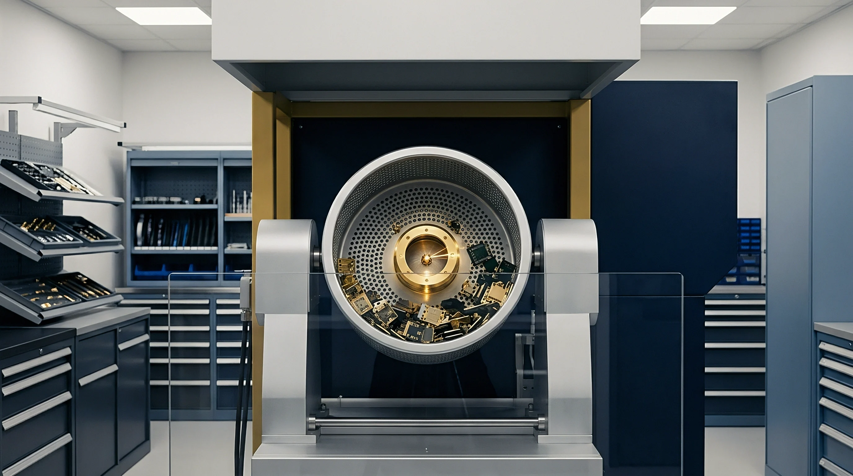
Baking drives out absorbed moisture through controlled kinetic desorption. Component preparation protocols rely on specific bake cycles to restore moisture-sensitive devices to a safe floor-life state before reflow soldering. Desorption efficiency depends on temperature, package geometry, compound thickness, and internal vapor pressure dynamics.
Oven atmospheres require low relative humidity to maintain steep concentration gradients that pull water molecules out from the package core.
JEDEC J-STD-033 Table 4-1 specifies a 24-hour thermal process at 125°C for Level 3 components exposed beyond 168 hours to eliminate internal steam pressure risks.
Drying kinetics follow the same basic mechanics as absorption, but with distinct hysteresis due to hydrogen bonding along the polymer backbone. Stripping bound water takes higher activation energy than removing free interstitial water. Standard 125°C bake cycles supply enough thermal energy to break those bonds, letting water diffuse to the surface and evaporate into the oven airflow.

Moisture Desorption Thermal Dynamics and Mass Extraction
Mass loss during baking follows an exponential decay curve. Initial outgassing is fast as free water near the surface evaporates into dry air. As moisture levels near the surface drop, the rate slows, constrained by how quickly water migrates from deep within the package.
Thicker package profiles require substantially longer bakes to dry out the interior core completely.
Desorption at 125°C removes moisture far faster than lower-temperature regimes. Measurements of silica-filled novolac compounds using precision analytical balances show that a 2.0 mm thick quad flat package requires 24 hours at 125°C to lower internal moisture below the safe 0.10 percent by weight threshold. Dropping the bake temperature to 90°C extends the required time to 64 hours for the same package, consuming significantly more of the thermal budget for heat-sensitive dies.

High Temperature Bake Schedules and Package Tolerances
Standard bake schedules balance drying speed against thermal degradation of leads and packaging materials. Lower bakes at 40°C or 90°C allow components to stay in high-temperature carrier tape, avoiding repackaging costs. Baking at 125°C, however, requires transferring parts from standard shipping tape into metal or heat-resistant plastic trays that won’t warp or outgas during thermal exposure.
Bake parameters depend on a component’s Moisture Sensitivity Level (MSL) and package thickness. J-STD-033 guidelines set minimum bake times according to out-of-bag exposure and factory ambient conditions. The table below outlines standard bake schedules used to reset floor life across different package thickness ranges.
| Package Thickness Band (mm) | MSL Rating Level | Bake Temperature 40°C (RH ≤ 5%) | Bake Temperature 90°C (RH ≤ 5%) | Bake Temperature 125°C (RH ≤ 5%) |
|---|---|---|---|---|
| ≤ 1.40 | Level 3 | 9 Days | 33 Hours | 9 Hours |
| ≤ 1.40 | Level 4 / 5 | 14 Days | 48 Hours | 14 Hours |
| ≤ 2.00 | Level 3 | 18 Days | 64 Hours | 18 Hours |
| ≤ 2.00 | Level 4 / 5 | 23 Days | 79 Hours | 24 Hours |
| ≤ 4.50 | Level 3 / 4 / 5 | 48 Days | 7 Days | 48 Hours |
| Values calculated for standard atmospheric pressure bake with air velocity exceeding 0.5 meters per second. | ||||

Kinetic Outgassing and Resin Cure Degradation
Repeated or extended bake cycles trigger unwanted chemical changes inside the mold compound. Prolonged exposure at 125°C drives residual cross-linking among unreacted epoxy groups, making the matrix brittle. At the same time, additives like flame retardants, silane coupling agents, and mold release waxes outgas from the polymer and condense onto exposed leadframe pins, degrading solderability during board assembly.
Cumulative baking also worsens dynamic package warpage. Differential shrinkage between the organic resin and inorganic silica filler creates internal residual shear stresses. Across multiple 125°C bake cycles, this stress can lift corner leads on fine-pitch packages off the seating plane.
Dynamic coplanarity measurements show offsets increasing by 0.015 mm to 0.030 mm after three 24-hour bakes, raising the risk of solder bridges or open joints during reflow.
Executing a component dry-bake sequence requires strict adherence to standardized material handling steps:
- Transfer surface-mount components from low-temperature carrier tapes into ESD-safe metal baking trays designed for thermal stability.
- Inspect tray arrangements to prevent lead overlap and ensure uniform airflow across all package surfaces.
- Calibrate forced-convection oven controls to maintain ambient temperatures within ±3°C of the setpoint.
- Run high-temperature bake cycles for the specified duration while keeping oven relative humidity below 5 percent.
- Cool baked components gradually to room ambient inside a desiccated cabinet to prevent thermal shock and condensation.
- Seal dried components immediately in moisture barrier bags with fresh desiccant and calibrated humidity indicator cards.
Baking consumes valuable production time and thermal budget. Bake schedules must target exact internal moisture thresholds to maintain lead solderability without causing thermal damage. Balancing moisture removal against component degradation requires accurate floor-life tracking across all manufacturing stock.
Exceeding recommended baking durations degrades leadframe plating solderability long before the epoxy matrix completes its structural outgassing period.


Interphase
Internal structural boundaries are prime failure points in encapsulated microelectronics. Moisture diffusing through the bulk mold compound collects at internal interfaces ~ including the die pad, silicon die surface, wire bonds, and leadframe surfaces. Local water concentrations at these boundaries often exceed bulk levels due to free volume segregation and thermodynamic energy traps.
Warm storage temperatures accelerate this accumulation, weakening interfacial adhesion well before components reach reflow soldering.
Interfacial shear strength relies heavily on chemical bonding from organosilane coupling agents added during resin synthesis. These organosilane molecules bridge inorganic substrates ~ like copper leadframes or silicon dioxide passivation ~ to the organic epoxy polymer network. Hydrolytic attack at elevated storage temperatures degrades these silane bonds, breaking covalent links and replacing them with weak physical interactions, which lowers delamination resistance across all internal packaging planes.

Silane Coupling Hydrolysis and Adhesion Decay
Water reaching the copper leadframe interface reacts directly with silane coupling bonds. Hydrolysis of siloxane links forms silanol groups, detaching the organofunctional tail from the metal surface. Warm storage accelerates this reaction, reducing interfacial fracture toughness by up to 60 percent compared to dry baselines.
Once chemical adhesion is lost, the bond relies entirely on mechanical interlocking from copper surface micro-roughness.
Specialized plating and mechanical profiling help leadframes resist hydrolytic decay. Micro-etched copper with dimpled surface structures maintains mechanical interlocks even after silane bonds fail. By contrast, smooth silver-plated die pads lack surface texture, leaving them highly vulnerable to total adhesion loss during warm moisture exposure.
Micro-cleavage along silver-epoxy interfaces is a leading cause of corner delamination in power QFN and SOIC packages.

When Does Moisture Vapor Pressure Exceed Mold Adhesion?
Rapid thermal exposure during reflow creates internal steam pressure that drives package delamination. As components travel through reflow ovens, package temperatures surge from 150°C to peaks of 260°C in 90 to 120 seconds. Water trapped at internal interfaces vaporizes instantly.
Vapor pressure in internal micro-voids follows the Clausius-Clapeyron equation, reaching 4.0 MPa to 5.5 MPa at 260°C peak reflow.
Delamination starts when local internal vapor pressure exceeds the critical adhesion strength of the mold compound. If high-temperature storage has already degraded silane bonds, adhesion strength can drop below 3.0 MPa at reflow temperatures. Under that pressure, steam expands micro-voids into full-scale delamination cracks across die pad boundaries.
The table below shows vapor pressure buildup alongside mold compound adhesion limits at various reflow temperatures.
| Reflow Temperature (°C) | Saturated Vapor Pressure (MPa) | Dry Mold Adhesion to Copper (MPa) | Moist Mold Adhesion after HTS (MPa) | Interfacial Delamination Margin (MPa) |
|---|---|---|---|---|
| 180 | 1.00 ± 0.05 | 14.5 ± 0.5 | 8.2 ± 0.4 | + 7.2 |
| 217 | 2.20 ± 0.08 | 11.0 ± 0.4 | 5.1 ± 0.3 | + 2.9 |
| 245 | 3.65 ± 0.12 | 8.5 ± 0.3 | 3.2 ± 0.2 | – 0.45 |
| 260 | 4.69 ± 0.15 | 7.2 ± 0.3 | 2.1 ± 0.2 | – 2.59 |
Vapor expansion stresses concentrate at sharp geometric features inside the package. Die pad corners, silicon die edges, and wire bond stitch points experience severe stress amplification. Modeling shows stress intensity factors at die pad corners are three times higher than across flat central regions.
Micro-cracks initiate at these corners and propagate laterally across the die-attach area during reflow.
Delamination along die pad interfaces breaks critical thermal dissipation pathways in high-power packages. If 50 percent of the die pad area separates, thermal resistance from the die junction to the circuit board can jump by up to 300 percent. Higher operating junction temperatures then trigger premature thermal shutdowns or accelerate silicon failure.

Hygrothermal Stress Concentration at Leadframe Corners
Combining temperature swings with absorbed moisture creates severe hygrothermal stress profiles. Differences in thermal expansion coefficients among the silicon die (2.6 × 10⁻⁶ /°C), copper leadframe (16.5 × 10⁻⁶ /°C), and epoxy mold compound (10 to 15 × 10⁻⁶ /°C below Tg) generate residual shear stress during post-mold cooling. Absorbed moisture swells the resin, layering hygrothermal stress directly on top of residual thermal stress.
Silane coupling agents degrade rapidly once localized moisture concentration at the die pad boundary reaches saturation during high temperature storage.
Hygrothermal shear stress on gold or copper ball bonds leads to bond pad cratering and wire shearing. Moisture reaching wire interfaces also drives electrolytic corrosion of intermetallic compound (IMC) layers, especially at gold-aluminum or copper-aluminum junctions. Trace halides from flame retardants dissolve in trapped water, creating corrosive ionic solutions that attack gold-aluminum intermetallics (Au4Al and Au8Al3).
This corrosion can degrade wire bond pull strength from a nominal 8.0 grams-force down to zero, opening the circuit.
Evaluating internal package interphase integrity demands systematic engineering selection criteria:
- Adhesion Promoter Selection requires organosilane chemistry optimized for thermal stability and hydrolysis resistance up to 260°C reflow temperatures.
- Leadframe Surface Roughness specifies micro-etched surface topologies exceeding 0.15 micrometers Ra to maximize mechanical interlocking.
- Die Attach Epoxy Compatibility matches thermal expansion profiles and outgassing behavior with the surrounding epoxy mold compound.
- Halide Content Limits restricts total chlorine and bromine ionic impurities in mold compounds to below 20 parts per million to prevent wire bond corrosion.
Internal delamination weakens the overall package structure, leaving it far more vulnerable to future environmental exposure. Water trapped inside delaminated gaps sits directly against active silicon, driving up leakage currents across fine-pitch bond pads. Reliability programs combine environmental stress testing with non-destructive acoustic inspection to catch interphase adhesion failures before components reach the field.
Allowing moisture-saturated packages with degraded silane interfaces to enter high-temperature reflow production lines results in instantaneous internal delamination, wire bond lifting, and catastrophic component yield loss.


Solder
Circuit board assembly exposes moisture-sensitive components to rapid, high-temperature thermal cycles. Surface-mount reflow brings package temperatures to peaks between 245°C and 260°C for lead-free alloys like tin-silver-copper (SAC300). Thermal stress paired with rapid internal steam generation puts extreme mechanical demand on the molding compound.
Defects caused by trapped steam show up as physical cracking, coplanarity shifts, or full package rupture.
“Popcorning” refers to the acoustic energy released when internal steam pressure expands delamination voids until the epoxy molding compound ruptures. Moisture beneath the die pad vaporizes, bulging the thin package floor downward. Once pressure exceeds the material’s tensile fracture strength at 260°C, a crack shoots from the die pad corner to the outer package surface with an audible pop.
Popcorning tears apart internal electrical connections and ruins external solder joints.

Reflow Spike Vaporization and Popcorning Failure Modes
Vapor pressure during the reflow thermal spike follows a non-linear curve. Preheat zones bring boards to 150°C ~ 200°C over 60 to 120 seconds, starting initial moisture movement. The final surge from 200°C to peak reflow at 260°C ramps at 1.5°C to 3.0°C per second.
This steep thermal gradient prevents moisture from diffusing out via standard Fickian mechanics, forcing rapid phase change inside micro-voids.
Package structural failure modes during reflow vary according to component geometry and internal stress distribution patterns:
- Type I Popcorning describes bottom-side mold cracking driven by steam pressure beneath large copper die pads.
- Type II Popcorning involves top-side cracking originating at the upper die surface, severing wire bonds.
- Type III Popcorning covers internal delamination confined to die pad boundaries without external cracking, leaving hidden thermal gaps.
- Type IV Popcorning identifies cracking along die edge corners driven by high shear stress combined with interfacial moisture accumulation.
Catching internal reflow damage requires non-destructive inspection. Scanning Acoustic Microscopy (C-SAM) uses ultra-high-frequency ultrasound (30 MHz to 230 MHz) to map density changes across internal package planes. Reflections pinpoint air gaps from delamination at die pad and leadframe interfaces down to 1.0 micrometer thickness.
Acoustic phase inversion confirms complete structural separation between the mold compound and metal substrate.

Leadframe Oxidation and Joint Shear Strength
Warm storage accelerates surface oxidation on exposed leadframe terminations. Copper leads stored above 80°C in open air form cuprous oxide (Cu2O) and cupric oxide (CuO) films. As these oxide layers thicken, they act as a physical barrier, preventing liquid solder from wetting the underlying copper during reflow.
Lead oxidation cuts solder joint shear strength on fine-pitch components. Solderability testing tracks the wetting balance force exerted by molten solder over time. Oxidized leads show delayed zero-cross wetting times exceeding 2.5 seconds, whereas clean leads reach zero-cross in under 0.5 seconds.
Poor wetting yields weak, void-riddled solder joints that fail under thermal cycling or board flexure.
Leadframe copper oxidation under elevated storage temperatures accelerates package micro-cracking during subsequent surface mount assembly.
Pre-assembly inspection requires verifying termination finish integrity. Standard solderability testing protocols specify dip-and-look evaluations or wetting balance analysis after extended thermal storage. The table below compares solderability metrics and joint shear strength across leadframe finishes subjected to high-temperature storage.
| Leadframe Finish Type | Thermal Storage Condition | Oxide Layer Thickness (nm) | Wetting Balance Time to Zero (s) | SAC305 Joint Shear Strength (MPa) |
|---|---|---|---|---|
| Matte Tin (10 µm) | 150°C for 500 Hours | 12.5 ± 1.5 | 0.85 ± 0.10 | 48.5 ± 2.5 |
| Bare Copper (Micro-Etched) | 150°C for 500 Hours | 85.0 ± 5.0 | > 5.00 (Failed) | 18.2 ± 4.1 |
| NiPdAu (Pre-Plated Frame) | 150°C for 500 Hours | 1.2 ± 0.3 | 0.35 ± 0.05 | 54.0 ± 1.8 |
| Tin-Lead Dip (63/37) | 150°C for 500 Hours | 18.0 ± 2.0 | 1.10 ± 0.12 | 45.0 ± 3.0 |

Land Pattern Geometry and Package Warpage Compensation
Dynamic package warpage during reflow complicates joint formation on high-density boards. Ball Grid Array (BGA) and Quad Flat No-Lead (QFN) packages change shape as temperatures climb from ambient to 260°C peak reflow. Asymmetric thermal expansion between the silicon substrate and mold compound causes spherical or shadow-corner warpage profiles.
Moisture-saturated compounds show even greater dynamic warpage because plasticization reduces the material’s elastic modulus.
Land pattern design rules in IPC-7351C help compensate for dynamic package distortion. Extending pad lengths by 0.10 mm to 0.15 mm beyond nominal footprints accommodates thermal movement without reducing solder fillet height. For fine-pitch BGA packages with a 0.50 mm pitch, pad geometry should use non-solder-mask defined (NSMD) pads, providing flexible anchors that absorb shear stress as the component cools.
Verifying component assembly readiness relies on specific quality assurance audit steps:
- Acoustic Microscopy Scanning inspects internal package interfaces for delamination voids exceeding 10 percent of total die pad area.
- Cross-Sectional Microscopic Inspection verifies solder joint intermetallic growth remains between 1.5 and 4.0 micrometers.
- Solderability Testing Standards confirm termination wetting coverage exceeds 95 percent of critical solder contact zones following thermal storage.
- Reflow Profile Temperature Ramp Rate limits heating rates to under 2.0°C per second to control vapor pressure generation speed.
Failure analysis in surface-mount manufacturing repeatedly confirms that ignoring moisture dynamics leads to field reliability issues. Micro-cracks formed during reflow act as pathways for environmental contaminants once products are deployed.
Internal micro-delamination detected post-reflow is often treated as falling within acceptable manufacturing limits if external package walls show no visible physical cracks.


Tariff
Managing moisture-sensitive components adds significant operational and logistics costs across electronic supply chains. Packaging, handling, floor storage, dry baking, and scrap disposal require dedicated capital and facility space. Parts classified under high Moisture Sensitivity Levels (MSL 3, 4, 5, and 5a) demand specialized packaging, controlled storage, and strict floor-life tracking prior to assembly.
Dry Barrier Packaging (DBP) standards require vacuum-sealed Moisture Barrier Bags (MBB), active silica gel desiccant, and chemical Humidity Indicator Cards (HIC). Packaging material for a standard ESD-shielded aluminum foil barrier bag costs between $0.45 and $1.20 per unit depending on size and film thickness. Automated packaging lines add equipment overhead for vacuum and heat sealing, adding another $0.08 to $0.15 per processed reel.

Landed Cost Penalty of Moisture Sensitive Packaging
Landed cost calculations need to account for the full expense of moisture control protocols. Standard components shipped in basic anti-static tape carry minimal packaging overhead. Moving parts to MSL 3 or higher introduces dry-pack processing, which adds labor, material, and documentation costs.
In low-margin, high-volume consumer electronics, that cost delta directly influences procurement strategy.
Evaluating landed cost structures helps pinpoint the break-even threshold between investing in factory-level dry storage versus paying for supplier-level dry packing. Installing automated dry cabinets that keep relative humidity below 1.0 percent requires an initial investment of $8,000 to $25,000 per cabinet. However, dry cabinets eliminate repeat baking labor and prevent thermal aging, typically paying for themselves within 14 months of continuous operation.

Dry Barrier Packaging Logistics and Shelf Life Depreciation
Shelf life inside sealed moisture barrier bags depends on the water vapor transmission rate (WVTR) of the film. Standard aluminum-laminated barrier bags specify a maximum WVTR under 0.002 grams per square meter per 24 hours at 40°C and 90 percent relative humidity. Under those conditions, manufacturers guarantee a 12-month shelf life from the initial seal date stamped on the caution label.
Once inventory passes the 12-month mark, bags must be opened, humidity indicator cards inspected, and components baked before placement. Warehouses holding expired stock incur extra costs to re-bake, re-reel, and re-seal components in fresh barrier bags. If a facility lacks baking equipment, expired stock must either be scrapped or sent back to distributors for reprocessing, eroding inventory value.

Scrap Rate Arithmetic for Expired Floor Life Stocks
Uncontrolled floor life exposure leads directly to high scrap rates. The moment a moisture barrier bag is opened, the clock starts. MSL 3 components allow up to 168 hours of exposure under standard factory ambient conditions (30°C and 60 percent relative humidity).
If parts sit unmounted past 168 hours, production protocols halt line feeding until they undergo an approved bake cycle.
Financial risk ramps up quickly when partial reels are left over after production runs. A partial reel of 1,500 ICs at $4.50 per unit represents $6,750 in unmounted inventory. If left exposed on the factory floor past its MSL floor life without dry cabinet storage or desiccant re-bagging, restoring the parts requires a 24-hour bake at 125°C. Evaluating whether to bake or scrap partial reels involves several direct cost factors:
Baking labor includes technician time to transfer components into thermal trays ($45.00), oven energy costs ($12.00), post-bake tape-and-reel repackaging ($125.00), and sample solderability testing ($150.00), bringing direct reprocessing costs to $332.00 per reel. Additionally, handling and thermal stress cause a 1.5 to 3.0 percent yield drop from lead damage and ESD events, writing off up to $202.50 in physical scrap per lot. Total recovery cost comes to $534.50 ~ 7.9 percent of the reel’s original value.
Failing to track floor life accurately lets compromised parts reach SMT assembly lines, where popcorning during reflow scraps entire board assemblies. Scrapping a fully populated board loaded with processors, memory, and power management ICs costs up to fifty times more than dry-pack processing would have in the first place.
JEDEC J-STD-033D Clause 5.3 stipulates that exposed moisture-sensitive components exceeding designated floor-life limits must undergo thermal bake processing matching Table 4-1 parameters before mounting onto printed circuit boards, legally binding assembly contractors to perform corrective desiccation actions under supply agreement quality terms.