Dielectric Window Phase Shift and near Field Ringing Dynamics under Thermal Gradients
Thermal gradients across dielectric windows alter permittivity and thickness, generating phase tilt errors and near-field ringing that require digital compensation.


Boundary
Dielectric radomes and hermetic sensor windows introduce phase distortion and reactive near-field ringing long before electromagnetic radiation reaches the far field. When an automotive millimeter-wave radar operating at 77 GHz or an industrial level sensor transmitting at 80 GHz emits through a solid polyetherimide or alumina flat plate, the air-to-dielectric interface causes a partial reflection. A thermal gradient across that window alters the local refractive index and thickness, warping the emerging wavefront and trapping transient energy inside the dielectric slab.
The resulting phase shifts degrade angular bearing calculations, while internal multipath bounces cause time-domain ringing that obscures short-range targets.
Phase error scales directly with the fractional change in optical path length. A temperature gradient across a polymer window introduces a spatial distribution of permittivity, turning an intended half-wavelength matching window into an uncalibrated phase-tilt wedge. Millimeter-wave beamforming arrays calculate target azimuth from phase differences between adjacent receiver channels; a two-degree differential phase error across a four-element subarray creates an apparent angular bias exceeding 0.6 degrees in 77 GHz FMCW automotive systems.
Near-field ringing occurs when the reflected wave bounces between the inner and outer boundaries of the window. In pulse-compression and frequency-modulated continuous-wave radars, this energy recirculates within the slab, entering the receiver as a low-frequency beat note or time-delayed ghost. The receiver treats this internal resonance as an echo originating mere centimeters from the feed horn.
An uncontrolled gradient broadens this beat frequency, leaking energy into adjacent range bins and desensitizing the low-noise amplifier stage.
A four-kelvin radial thermal gradient across an automotive 77 GHz polyetherimide radome shifts the baseline transmission phase by 1.8 degrees and degrades adjacent channel cross-isolation below 26 dB.
Selecting window materials requires balancing mechanical durability against thermal stability. Polycarbonate exhibits a thermal coefficient of permittivity of negative 4.2 times ten to the fourth power per kelvin, alongside a linear thermal expansion coefficient of 65 parts per million per kelvin. Alumina ceramics maintain a positive thermal coefficient of permittivity, changing at roughly 1.1 times ten to the fourth power per kelvin, but expand at only 7.2 parts per million per kelvin.
The sign and magnitude of these coefficients govern whether an operating thermal gradient sharpens or degrades internal impedance matching.
When the dielectric structure forms a structural seal over an antenna feed, heat conducted from internal power amplifier dies and baseband processors generates a stable radial temperature profile. Heat dumps into the window center while mounting flanges act as thermal sinks, establishing a stationary gradient that standard static phase calibration cannot decouple from dynamic ambient shifts.
System designers compensate for these shifts by characterizing window behavior across both steady-state environments and rapid thermal transitions. Failure to model dielectric ringing dynamics leaves sensors blind within their immediate non-zero velocity range cells, where reflection artifacts overpower return signals from real physical targets.


Permittivity
Wave propagation velocity inside a non-magnetic dielectric medium is governed by the relative complex permittivity of the material. The real part of this property establishes the phase velocity and intrinsic wave impedance, while the imaginary component dictates dielectric attenuation per meter. When ambient temperatures drift or localized heaters fire, the real permittivity fluctuates according to the polarizability of the polymer chains or crystalline lattice.
Thermal coefficients of permittivity, designated as the temperature derivative of relative permittivity, define the magnitude of phase error across varying operational states. Non-polar polymers such as polytetrafluoroethylene experience a drop in permittivity as temperature climbs, because volumetric expansion decreases molecular number density. Crystalline ceramics often experience increased permittivity at elevated temperatures, caused by lattice ionic polarizability overriding thermal volumetric expansion.

Electrodynamics of Thermally Stressed Slabs
Phase accumulation through a flat slab of thickness d at normal incidence is governed by the free-space wave number multiplied by the refractive index and the physical thickness. Differentiating this total phase shift with respect to temperature isolates two competing physical mechanisms:
Differential phase change per unit temperature equals the product of free-space wave number and the sum of the linear thermal expansion coefficient multiplied by the refractive index, plus the derivative of refractive index with respect to temperature. For optical and millimeter-wave frequencies, the refractive index is taken as the square root of the real permittivity. A thermal expansion that increases window thickness elongates the physical path length, while a negative temperature coefficient of permittivity shortens the electrical path length.
Cross-sensitivities multiply when materials encounter high ambient humidity. Hydrophobic substrates such as cyclic olefin copolymers prevent moisture absorption, maintaining stable real permittivity values near 2.35 from minus 40 to 85 degrees Celsius. Polyamides absorb atmospheric water vapor up to three percent by weight, increasing real permittivity from 3.1 to over 3.8 and increasing loss tangents from 0.009 to 0.045 at 24 GHz, swamping thermal phase shifts under shifting atmospheric conditions.
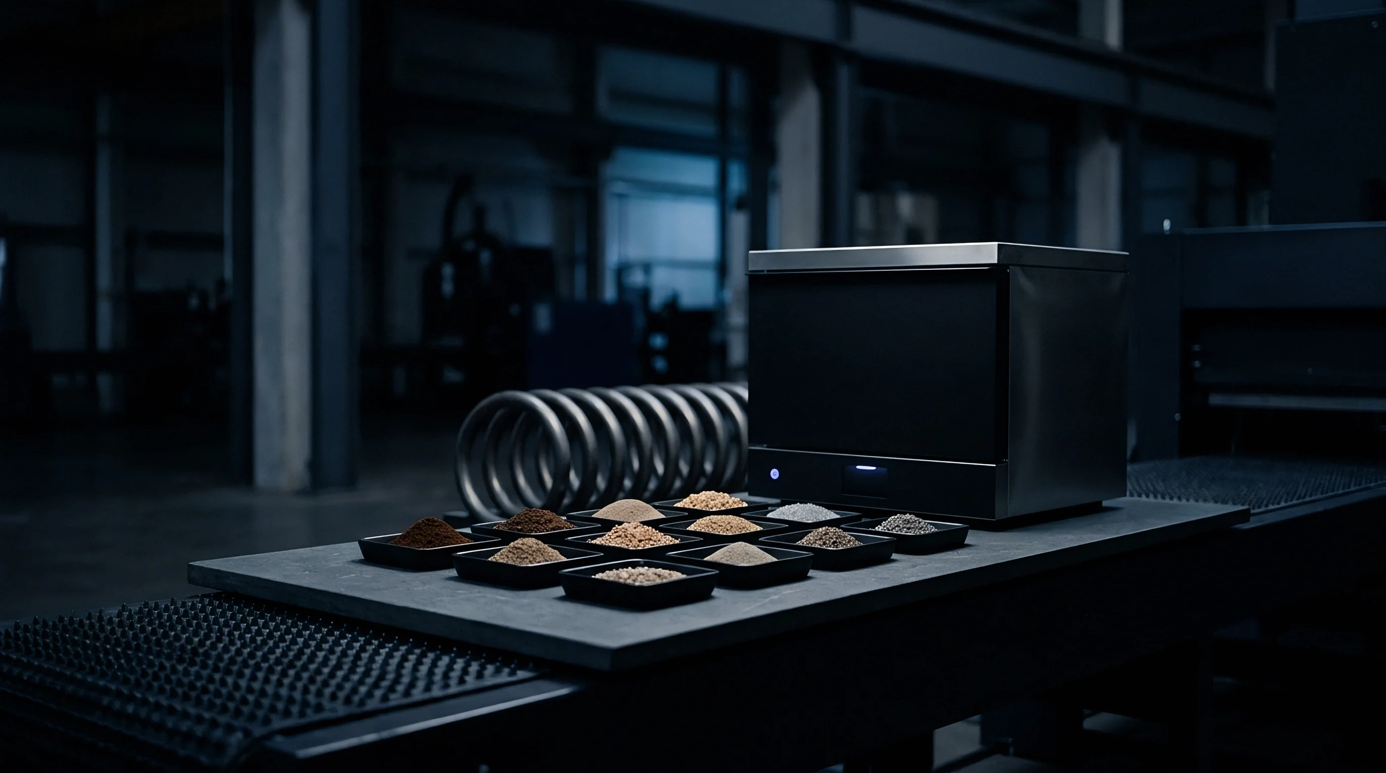
Substrate Dielectric Behavior under Thermal Loads
Evaluation of candidate radome and window materials requires analyzing electrical properties alongside physical thermal expansion characteristics. The table below presents real permittivity, loss tangent, temperature coefficient of permittivity, and thermal expansion properties measured between minus 40 and 105 degrees Celsius across common sensor window materials.
| Substrate Material | Permittivity Real | Loss Tangent | Thermal Permittivity Coefficient (1/K) | Expansion Coefficient (ppm/K) |
|---|---|---|---|---|
| Polycarbonate (PC) | 2.78 | 0.0092 | -4.2e-4 | 65.0 |
| Polyetherimide (PEI) | 3.15 | 0.0045 | -3.1e-4 | 56.0 |
| Cyclic Olefin Copolymer (COC) | 2.35 | 0.0007 | -1.8e-4 | 60.0 |
| Alumina 99.5% (Al2O3) | 9.80 | 0.0003 | +1.1e-4 | 7.2 |
| Fused Silica (SiO2) | 3.82 | 0.0002 | +0.8e-4 | 0.5 |
| High-Density Polyethylene (HDPE) | 2.32 | 0.0004 | -2.9e-4 | 120.0 |
Selecting a material with near-zero temperature coefficients does not eliminate window effects when thickness variations are present. Mechanical tolerances across injection-molded polymers introduce baseline thickness variations of plus or minus 25 micrometers. At 77 GHz in a polyetherimide window, a 25-micrometer variation alters baseline transmission phase by 11.4 degrees, overshadowing the phase shift caused by a ten-degree uniform temperature rise.
Incoming inspection procedures therefore require sub-mil positional wall-thickness mapping alongside material batch permittivity verification. A supplier may deliver resin within certified bulk density boundaries, yet differential shrinkage during cooling yields molded windows with internal density variations that manifest as static phase distortions before thermal loads are introduced.


Ringing
Internal reflections within a dielectric window create a resonant Fabry-Pérot cavity directly in front of the antenna array. An ideal half-wavelength window presents an electrical thickness equal to an integer multiple of pi radians, setting net interface reflections to zero for a single incident angle and frequency. When a thermal gradient alters this electrical thickness, reflection coefficients at the boundaries decouple from the cancellation state, initiating multipath recirculation.
The time-domain signature of this recirculation is near-field ringing. A fraction of the transmitted energy reflects from the air-dielectric interface back toward the antenna feed horn, reflects off the feed or circuit ground plane, and re-traverses the window toward the outside world with a fixed time delay. In FMCW radar systems, this delay manifests as a static beat frequency inside the receiver baseband, creating a persistent blind range zone.

Fabry-Pérot Cavity Dynamics
The quality factor of the dielectric slab cavity dictates how long energy rings before falling below the receiver thermal noise floor. Cavity Q relates directly to interface reflection coefficients and dielectric loss tangent:
When the dielectric constant is elevated, as with 99.5 percent alumina, normal-incidence air-interface reflection coefficients reach 0.52. This high reflection traps electromagnetic energy for multiple round trips, prolonging the duration of ringing tails. Polymeric windows with lower real permittivity values near 2.3 produce interface reflections around 0.21, significantly damping multipath ringing cycles.
High-dielectric materials demand tightly toleranced quarter-wave impedance matching layers to achieve equivalent ringing decay rates.
Quarter-wave matching layers deposited without matching thermal expansion coefficients delaminate under thermal cycling, shifting the return-loss null away from target operating frequencies.
Thermal gradients deform the planar nature of internal reflections. A center-to-edge gradient turns the window into an irregular resonant cavity with non-parallel phase fronts. Bounced energy diverges within the slab, coupling into surface waves and substrate modes that propagate laterally toward the metallic mounting bracket, where they scatter into antenna sidelobes.

Are Ringing Artifacts Distinguishable from Point Targets?
Baseband signal processors must identify whether a low-frequency spectral peak represents an immediate physical obstruction or internal window ringing. The operational behavior of these signatures diverges across frequency sweeps and thermal profiles.
- Range gate localization reveals stationary spectral components locked to the round-trip delay time of the housing cavity, spanning equivalent optical distances under thirty centimeters.
- Doppler bin distribution indicates that internal ringing energy concentrates within the zero-velocity channel, whereas genuine vehicular or fluid targets introduce finite Doppler frequency offsets.
- Chirp slope dependence shifts the absolute beat frequency when modulation parameters change, exposing fixed-delay ringing artifacts that scale proportionally with sweep rates.
- Phase trajectory tracking exposes continuous thermal drifts in the window echo that track chassis temperature sensors, separating internal returns from stationary external clutter.
Ringing energy degrades receiver performance when mixer non-linearities and phase noise are present. Strong near-field reflections mix with transmitter phase noise to raise the baseband noise floor, a phenomenon termed transmitter leakage de-sensitization. The elevated noise floor masks weak signals returning from distant targets with small radar cross-sections.
Mitigating this ringing requires holding the dielectric thickness precisely to an integer multiple of half-wavelengths across operating temperatures, or angling the window relative to the antenna boresight. Tilting the window directs specular reflections into absorber materials lining the housing interior, stopping multipath energy from returning to the array face.

Distortion
Wavefront phase distortion caused by non-uniform window temperatures alters the directional characteristics of antenna arrays. Unlike a uniform temperature shift that changes electrical thickness evenly across all channels, spatial thermal gradients generate localized, position-dependent phase advances or delays across the array aperture. The resulting beam tilting, gain reduction, and sidelobe degradation compromise measurement integrity.
In directional radar and imaging sensors, angles of arrival are computed by evaluating phase differences across distinct antenna elements. A phase error appearing on an outer element tilts the calculated pointing vector, inducing an angular bearing bias. This angular pointing error maps directly to wavefront phase tilt:
Angular deviation equals the spatial phase gradient divided by the free-space wave number. A linear phase gradient of 0.05 radians per millimeter at 77 GHz produces an apparent angular shift of 1.1 degrees. In automotive forward-looking radar, an undetected 1.1-degree bearing error projects an apparent cross-track position error of 3.8 meters at a range of two hundred meters, placing a detected target into an adjacent highway lane.

Sidelobe Growth and Array De-Correlation
Nonlinear thermal gradients distort wavefronts into quadratic and higher-order shapes, degrading beam focus. A parabolic temperature distribution across a window functions like a dielectric lens, shifting the effective focal length of the antenna system and widening the primary beamwidth. This broadening lowers peak antenna gain, cutting maximum sensor detection range.
Wavefront ripple and high-order phase errors scatter energy away from the main beam into antenna sidelobes. Increased sidelobe levels raise susceptibility to false alarms from out-of-beam clutter, including guardrails, roadside structures, or industrial tank fittings. Energy leaking into sidelobes compromises target resolution, merging closely spaced echoes into indeterminate single detections.
Differential phase errors also compromise mutual channel cross-isolation. Phased-array beamformers depend on uniform channel-to-channel matching to suppress interference and synthesis nulls. Window-induced phase distortion unbalances receiver channels, degrading achievable array null depth from 45 dB down to less than 22 dB under severe thermal stresses.
Standard factory beam-pattern calibration fails when thermal gradients warp antenna aperture phase profiles dynamically in operational field environments.
Thermal gradients often manifest three-dimensional profiles that vary across time. Solar radiation falling across one half of an external sensor radome combined with vehicle forward airflow creates a dual-axis temperature differential. The resulting phase distribution skews azimuth and elevation angle calculations simultaneously, corrupting sensor tracking filters and tracking algorithms.


Chamber
Verifying window phase shift and ringing dynamics requires specialized bench apparatus that decouples environmental effects from transceiver electronics. Placing an entire sensor module into an environmental chamber verifies complete system operation, but conceals whether observed phase errors stem from window dielectric shifts, circuit board expansion, or transceiver silicon drift. Direct evaluation requires dedicated optical transmission test benches fitted with controlled thermal gradient drivers.
A rigorous measurement setup features a vector network analyzer operating across 75 to 110 GHz, driving focused Gaussian beam horn antennas. The dielectric window under test is held inside a dual-zone thermal enclosure positioned at the beam waist. A localized infrared radiant heating array projects a known thermal pattern across the exterior face, while liquid-cooled brass perimeter clamping plates maintain window edges at a stabilized reference temperature.

Vector Transmission Diagnostics
Calibration of the free-space measurement bench uses Thru-Reflect-Line (TRL) or Free-Space TRL standards implemented at the Gaussian beam waist. Measuring complex transmission parameters (S21) across the sweep frequency band yields insertion phase and attenuation through the window. Comparing these values across isothermal and gradient states reveals the magnitude of the thermally induced phase perturbation.
Internal multipath ringing appears as high-frequency ripple superimposed on the S21 and S11 frequency response plots. Applying a Fourier transform to the frequency-domain scattering data converts measurements into the time domain, resolving internal Fabry-Pérot bounces into distinct time-resolved peaks. The first peak marks the direct path transmission, while subsequent decaying peaks trace internal round trips through the window core.

Worked Case of Phase Shift across a Gradient
Consider an injection-molded polyetherimide window specified for an automotive 77 GHz radar sensor, operating under cold winter conditions where internal electronics heat the window core. Assumptions for this worked calculation follow:
The window is designed as a half-wavelength slab at nominal 20 degrees Celsius. Window center reaches 65 degrees Celsius from internal board conduction, while edges are chilled to minus 15 degrees Celsius by forward vehicle velocity, generating a 40-kelvin center-to-edge gradient. Window parameters are:
Physical thickness equals 1.100 millimeters. Real permittivity at 20 degrees Celsius equals 3.150. Thermal permittivity coefficient is negative 3.1 times ten to the fourth power per kelvin.
Linear thermal expansion coefficient is 56 parts per million per kelvin. The operational frequency is 76.5 GHz, yielding a free-space wavelength of 3.919 millimeters.
At the center zone, temperature rises by 45 kelvin relative to the design baseline. Center thickness expands by 0.0028 millimeters to 1.1028 millimeters. Center real permittivity drops by 0.01395 to 3.13605.
Center refractive index drops from 1.7748 to 1.7709. Phase accumulation through the center equals 2 times pi divided by 3.919 multiplied by 1.1028 and 1.7709, yielding 3.134 radians, or 179.56 degrees.
At the cold perimeter zone, temperature drops by 35 kelvin relative to the design baseline. Perimeter thickness shrinks by 0.0022 millimeters to 1.0978 millimeters. Perimeter real permittivity rises by 0.01085 to 3.16085.
Perimeter refractive index rises from 1.7748 to 1.7779. Phase accumulation through the perimeter equals 2 times pi divided by 3.919 multiplied by 1.0978 and 1.7779, yielding 3.131 radians, or 179.39 degrees.
The net phase differential between center and perimeter across this thermal gradient equals 0.17 degrees of transmission phase. While seemingly small for a pure half-wavelength slab where thickness expansion and permittivity drops partially cancel, the interface reflection coefficient shifts from an ideal match of zero to minus 28 dB at the center and minus 29 dB at the edge, causing unexpected multipath ringing.
Environmental verification protocols must adhere to international testing standards, specifically IEC 60068-2-14 test methods for thermal shock and continuous gradient testing. Test execution requires recording the spatial temperature profile with a calibrated thermal imaging camera operating in the 8 to 14 micrometer band, verified against surface thermocouples bonded directly to the window face.
The supplier will maintain that testing windows under uniform thermal conditions validates compliance with the master specification sheet. That claim fails because uniform oven testing balances thickness shifts across the entire surface, concealing the spatial phase gradients and localized ringing spikes that occur only under non-uniform thermal loads.


Compensation
Mitigating the effects of dielectric window phase shifts and near-field ringing demands both hardware architectural revisions and digital compensation routines within the signal processing chain. When mechanical constraints prevent shifting to zero-expansion, high-cost materials, signal-chain engineering absorbs remaining phase errors and suppresses multipath reflections.
Hardware-level mitigation begins by modifying the mechanical profile of the window. A window oriented perpendicular to the antenna bore inevitably directs ringing reflections back into receiver elements. Introducing an intentional tilt angle of 7 to 12 degrees deflects specular reflections away from the array, guiding bouncing waves into lossy radar-absorbing elastomers positioned inside the housing perimeter.

Mechanical and Material Strategies
Engineers can reduce reflection levels by specifying multi-layer impedance-matching skins or molded quarter-wave matching structures on both faces of the dielectric slab. These quarter-wave matching layers reduce air-interface reflections across wider operational bandwidths, minimizing the amplitude of internal ringing tails even as temperatures drift away from design points.
Controlled thermal paths reduce temperature variations across the window face. Integrating thermal conduction spreaders around the window periphery shunts heat away from internal processing units to external chassis heatsinks, preventing internal heat from dumping directly into the radome center. Thermal design must restrict radial surface temperature gradients below 0.1 kelvin per millimeter under peak operating loads.
Firmware Dynamic Correction Workflow
Modern radar transceivers implement real-time phase compensation algorithms inside on-chip microcontrollers or field-programmable gate arrays. This digital workflow counteracts phase drift and dynamic near-field clutter through deterministic correction routines.
- Chassis thermal telemetry acquisition reads multiple embedded temperature sensors distributed across the radome perimeter and internal transmitter ground plane every ten milliseconds.
- Permittivity lookup and interpolation queries a factory-calibrated polynomial matrix mapping local window temperatures to real dielectric constants and phase corrections.
- Wavefront phase adjustment applies complex phase correction vectors to raw digital baseband channels before steering beams or calculating angular bearings.
- Zero-Doppler clutter filtering suppresses fixed-frequency near-field ringing artifacts across initial range gates, preventing leakage from masking immediate targets.
- Adaptive background cancellation updates a running spatial clutter map during operation, subtracting persistent low-level window reflections from baseband data frames.
Digital compensation relies on the precision of the factory calibration lookup table. If mold shrinkage or machining tolerances create part-to-part wall thickness variations exceeding 15 micrometers, a single generic temperature compensation model applied across all production units leaves residual phase errors up to 4 degrees. High-performance systems require individual unit calibration across temperature during end-of-line verification.
Dynamic phase compensation tables become invalid when water films or de-icing chemical residues accumulate unevenly on the exterior radome face.
External surface contaminants alter the boundary condition at the outer interface, adding complex dielectric loading that onboard temperature lookup routines cannot predict. Advanced sensor firmware combines thermal lookup corrections with adaptive target-tracking algorithms that detect surface degradation by monitoring long-term variations in average near-field reflection power.
When physical tilting, impedance matching, and digital compensation are executed in concert, residual angular bearing errors from thermal gradients drop below 0.05 degrees, and near-field ringing collapses by more than 35 dB, restoring the dynamic detection range of the sensor system.


Allocation
The choice between low-cost injection-molded polymers and precision ceramics fixes the bill of materials cost, the qualification timeline, and the supplier landscape. Polymers like polycarbonate and polyetherimide require modest material expenditure, with molded radome units costing between 0.80 and 3.50 dollars at volume. Alumina ceramics and fused silica windows, manufactured via hot-pressing and diamond grinding, command prices from 28.00 to 110.00 dollars per unit, confining their use to defense, aerospace, and specialized process instrumentation.
This material choice dictates commercial sourcing exposure. High-volume polymers depend on global chemical conglomerates for resin supplies, followed by regional tier-two injection molders who control tooling and shrinkage tolerances. Precision ceramics depend on a narrow supply base of specialized technical ceramic manufacturers operating across Japan, Germany, and the United States, where production capacity is constrained and tooling lead times can stretch past 36 weeks.

Supply Base Parameters across Window Technologies
Selecting window materials requires evaluating production tolerances, pricing structures, and qualification risks alongside basic electromagnetic properties. The table below outlines sourcing metrics for primary window substrates used in commercial and industrial millimeter-wave sensing applications.
| Window Technology | Unit Cost Range (USD) | Tooling Lead Time (Weeks) | Dimensional Tolerance (µm) | Global Supplier Pool |
|---|---|---|---|---|
| Polycarbonate Injection-Molded | 0.80 to 2.20 | 10 to 14 | ±25 | Over 50 Qualified Molders |
| Polyetherimide Precision-Molded | 1.80 to 4.50 | 12 to 18 | ±15 | 15 to 25 Qualified Molders |
| Cyclic Olefin Copolymer (COC) | 3.20 to 6.80 | 14 to 20 | ±15 | 8 to 12 Specialized Molders |
| Alumina Ceramic Grinded (99.5%) | 28.00 to 65.00 | 24 to 32 | ±5 | Under 6 Global Producers |
| Fused Silica Optical-Grade | 45.00 to 110.00 | 26 to 36 | ±2 | Under 4 Specialized Producers |
Specifying tight mechanical tolerances on polymer windows to reduce phase errors rapidly impacts manufacturing yields. Demanding injection-molded polyetherimide thickness variations below plus or minus 10 micrometers drops molding line yields from 94 percent down to under 65 percent, driving unit component costs up through scrap rates. Mold cavitation must be restricted to single or dual cavities to maintain uniform pressure and cooling profiles across the tool.
Procurement documents must specify incoming inspection protocols that verify wall thickness profiles and resin batch dielectric constants under ASTM D2520 test methods. A component drawing that specifies only external envelope dimensions without defining high-frequency dielectric constant tolerances allows suppliers to alter resin lot stabilizers and colorants, altering high-frequency transmission characteristics without violating mechanical drawings.
Purchasing contracts must include explicit clauses defining dielectric properties: lot acceptance requires that raw resin dielectric constants at 77 GHz stay within plus or minus 0.02 of nominal, with high-frequency dissipation factors certified via cavity perturbation testing on every resin batch. Inserting these requirements safeguards against baseline phase drift and unpredictable near-field ringing dynamics before parts enter final assembly lines.