Precision Capacitive Accelerometer Thermo Mechanical Bias Stability Basics
Precision capacitive MEMS accelerometer thermo-mechanical bias stability requires stress-isolated ceramic packaging and gradient-aware temperature calibration.

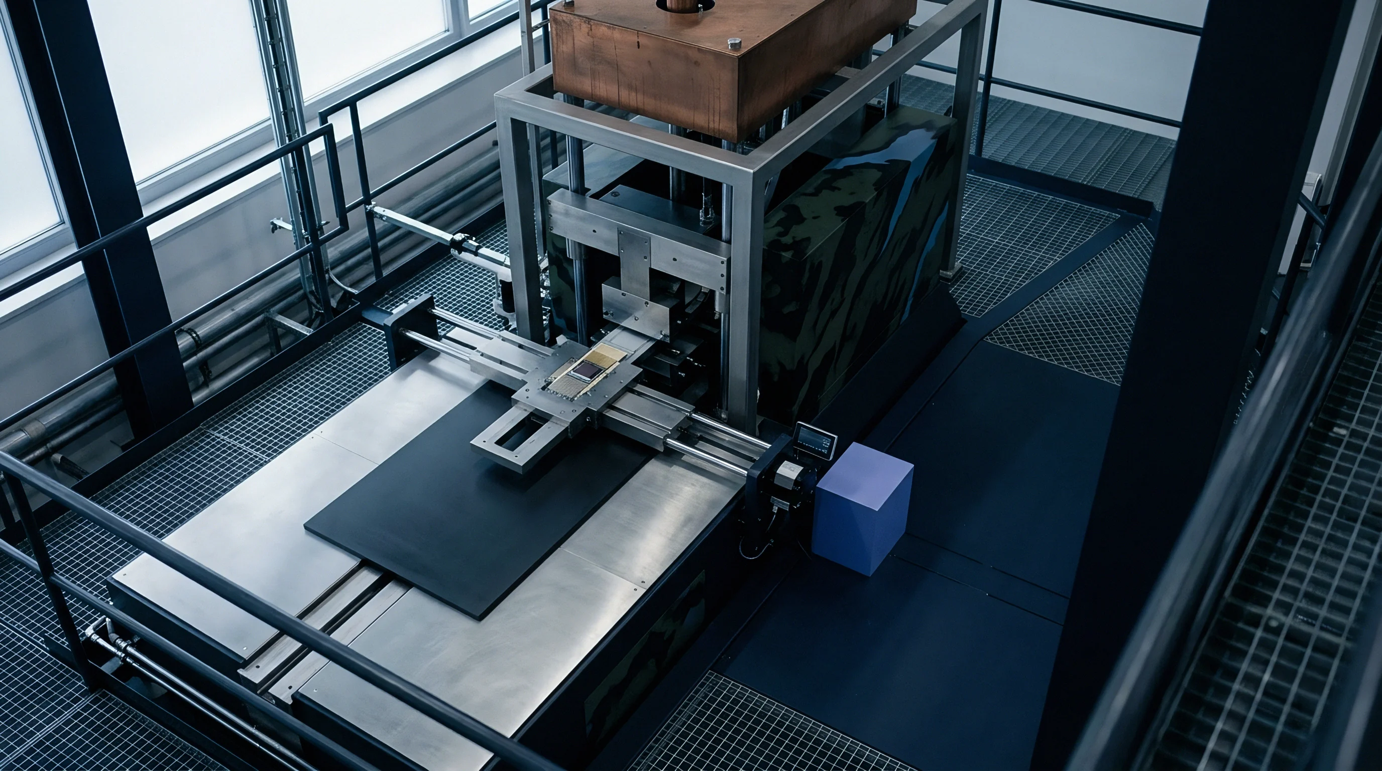
Die
Micro-electromechanical capacitive accelerometers convert physical acceleration into capacitance changes through suspended silicon proof masses and interdigitated comb finger structures. Variable capacitance micro-sensors rely on micrometer-scale air gaps between fixed stator fingers and movable rotor fingers. Acceleration displaces the suspended proof mass against silicon flexure springs, altering the nominal capacitance according to the differential air gap equation:
Δ C = C1 – C2 = ε0 εr A left( frac1d0 – x – frac1d0 + x right) ≈ 2 C0 fracxd0
In this differential electro-mechanical relation, C0 denotes the nominal zero-acceleration capacitance, d0 represents the un-displaced resting air gap, and x signifies mechanical displacement along the sensitive axis. High-precision capacitive elements operate with nominal gap spacing between 1.0 and 2.5 micrometers, yielding baseline capacitances ranging from 0.5 to 5 picofarads per sensing channel. Sub-femtofarad capacitance shifts correspond to micro-gravity accelerations.
Silicon flexure springs govern physical displacement through the spring constant k, establishing the fundamental zero-acceleration offset position.

Temperature Dependent Silicon Modulus and Rest Position Shift
Thermal variations directly affect the structural spring constant through the temperature coefficient of Young’s modulus in single-crystal silicon. Silicon exhibits a negative thermal modulus coefficient, typically -30 to -60 p±/K depending on crystallographic orientation and doping concentrations. As ambient temperature increases, silicon flexures soften, increasing mechanical displacement under constant gravitational or inertial loading.
Unbalanced mechanical rest positions occur when micro-fabrication etching tolerances create microscopic asymmetries between opposing flexure arms. Silicon anchors flex under heat. A resting displacement shift of merely 0.1 nanometer alters the zero-acceleration capacitive equilibrium, producing an uncalculated bias drift at the sensor output.
Differential thermal expansion between the single-crystal silicon sensing structure and the underlying glass or silicon substrate introduces residual mechanical moments. Glass-frit bonds, anodic bonds, and silicon-on-insulator fusion boundaries transmit thermo-mechanical shear forces directly into the anchor points. When temperature shifts across the operating band of -40circC to +125circC, localized thermal expansion variations distort the stator finger alignment relative to the rotor.
The proof mass shifts position. Ascorrected tilt, baseline acceleration reading offsets, and asymmetric cross-axis sensitivity changes occur purely due to internal micro-structural deformation without external mechanical motion.
Single-crystal silicon exhibits a temperature coefficient of Young’s modulus between minus thirty and minus sixty parts per million per Kelvin, causing measurable suspension spring softening across industrial thermal operating ranges.
Differential capacitance micro-geometries partially cancel symmetric thermal expansion through push-pull readout architectures. However, non-uniform thermal expansion along the orthogonal axis warps the proof mass frame. Frame warping shifts the inter-finger overlapping area A, altering capacitance independent of the primary air gap d0.
Precision devices minimize this cross-axis displacement by employing central single-point anchor designs that isolate the active sensing zone from surrounding substrate deformation. Solder strain alters zero bias. Devices featuring perimeter-anchored suspensions suffer elevated thermo-mechanical drift due to unconstrained frame distortion.
Sensors incorporating differential mechanical suspensions exhibit lower zero-g offset thermal coefficients than single-ended topologies. Symmetric layout topologies enforce balanced mechanical expansion along both positive and negative displacement vectors. Achieving thermal stability below 100 μg/K requires keeping internal mechanical tolerances within single-digit nanometer limits across wafer-scale manufacturing runs.


Stress
Packaging mechanics represent the primary source of operational zero-acceleration offset drift in micro-machined capacitive sensing elements. Silicon dies possess an isotropic Coefficient of Thermal Expansion (CTE) of approximately 2.6 × 10⁻⁶/K at room temperature. Printed circuit boards manufactured from standard FR4 glass-reinforced epoxy exhibit bulk thermal expansion coefficients between 14 × 10-6/K and 17 × 10-6/K. Ceramic land grid array substrates bridge this thermal expansion gap with coefficients around 6 × 10⁻⁶/K to 7.5 × 10⁻⁶/K. Thermal expansion mismatches across material interfaces generate mechanical shear forces that propagate directly into the sensitive silicon suspension structures.

Asymmetric Package Mechanical Expansion Dynamics
Bonding material selection governs how environmental temperature swings transfer structural force into the underlying die. Die attach adhesives made of organic epoxy feature thermal expansion coefficients from 30 × 10-6/K to 60 × 10-6/K, introducing compliant yet viscoelastic interface layers. Solder die attachment using eutectic gold-tin alloys provides high structural stiffness but transfers printed circuit board bending forces directly into the micro-structure.
Dynamic thermal gradients across the sensor package generate transient mechanical bending moments (nabla T). Thermal gradients bend the die. These transient bending forces produce non-linear zero-acceleration output spikes during rapid thermal cycling.
| Package Construction Type | Substrate Material CTE (10^-6 / K) | Die Attach Material | Zero-g Bias Drift Coefficient (μg / K) | Thermal Hysteresis Residual (μg) |
|---|---|---|---|---|
| 14.0 – 17.0 | Conductive Epoxy | 150 – 450 | 250 – 800 | |
| 6.5 – 7.5 | Silicone Elastomer | 30 – 90 | 50 – 150 | |
| 6.0 – 7.0 | Eutectic AuSn / Pedestal | 5 – 25 | 10 – 40 | |
| 2.6 (Bare Silicon) | Polymer Underfill | 80 – 200 | 120 – 350 |

Do Thermomechanical Stress Gradients Permanently Alter Zero-G Bias?
Viscoelastic relaxation in polymeric die adhesives creates time-dependent offset drift following severe thermal excursions. Exposure to elevated temperatures softens organic adhesives, allowing accumulated internal shear forces to dissipate slowly over hundreds of operating hours. When the sensor cools back to ambient temperature, the adhesive freezes in an altered geometric state.
This microscopic shape change leaves residual mechanical strain across the silicon anchors. Permanent offset changes occur when thermal cycles exceed the glass transition temperature (Tg) of the structural adhesive. Plastic deformation in the board mount solder joints similarly creates permanent offset offsets following system-level thermal shock events.
- Anisotropic Substrate Expansion produces non-uniform lateral shear forces that twist the micro-machined frame and misalign capacitive comb structures.
- Solder Creep Stress Relaxation shifts the zero-acceleration equilibrium point over prolonged high-temperature operational exposure periods.
- Moisture Absorption Swelling expands plastic mold compounds, applying compressive forces to encapsulated silicon dies.
- Thermal Gradient Bending introduces transient offset spikes during rapid environmental temperature transitions.
Mounting accelerometers onto heavy glass-epoxy circuit boards without mechanical isolation slots exposes the silicon element to printed circuit board flexure. Board warping caused by housing attachment screws or adjacent high-power heat sources introduces mechanical strain directly into the package pads. Hermetic ceramic packages featuring internal stress isolation pedestals decouple the active silicon element from external board bending forces, keeping zero-g bias changes within narrow bounds.
Neglecting thermo-mechanical packaging strain during initial mechanical layout renders subsequent high-order electronic calibration routines ineffective over long operational lifetimes.


Conditioning
Front-end electronic interface circuits convert sub-femtofarad variable capacitance changes into high-resolution digital values. Switched-capacitor charge amplifiers operate as the primary stage, periodically transferring charge between the MEMS comb capacitors and internal integration capacitors (Cint). The output voltage of a fully differential charge amplifier relates directly to the capacitance differential:
Vout = Vref left( fracΔ CCint right) = Vref left( fracC1 – C2Cint right)
Operational stability depends directly on the thermal coefficient of the internal reference voltage source Vref and the feedback integration capacitance Cint. Voltage reference noise masks small signals. Bandgap reference circuits exhibiting 10 p±/K thermal drift introduce artificial zero-acceleration output changes across wide operating temperatures.
Integrating auto-zeroing topologies, correlated double sampling, and chopper stabilization reduces low-frequency 1/f amplifier noise and offsets voltage drift, isolating the real mechanical capacitance shifts.

ASIC Parasitic Capacitances and Clock Thermal Sensitivity
Bond wire connections, input ESD protection diodes, and integrated circuit routing traces introduce fixed parasitic capacitance (Cp) in parallel with the sensing element. Parasitic capacitance values often exceed the baseline sensor capacitance C0 by an order of magnitude. Unbalanced thermal expansion in wire bonds and package leadframes shifts Cp at rates between 0.1 fF/K and 1.0 fF/K. Switched-capacitor excitation clocks must maintain precise phase alignment and frequency stability; clock jitter and thermal frequency drift alter charge transfer timing, appearing at the system output as zero-g bias instability.
A bandgap voltage reference exhibiting five parts per million per Kelvin thermal drift introduces up to one hundred twenty micro-g equivalent zero offset shift across an industrial operating range of minus forty to eighty-five degrees Celsius.
Integrated temperature sensors on the conditioning Application-Specific Integrated Circuit (ASIC) track silicon die temperatures to enable active electronic correction. On-chip sensors track die heat. Physical separation between the sensing ASIC and the MEMS mechanical element introduces dynamic thermal response lags.
During rapid temperature transitions, the ASIC heating rate leads or lags the mechanical mass temperature by several degrees. The readout circuit applies temperature compensation factors based on outdated thermal values, generating significant transient zero-g bias errors during thermal ramps.
Component manufacturers often claim that internal digital signal processing engines eliminate all temperature-induced offset variations. Laboratory evaluation reveals that single-point factory calibration fails to account for thermal hysteresis or mechanical stress developed after surface-mount assembly.


Modeling
Algorithmic compensation reduces residual zero-acceleration thermal drift by processing die-level temperature sensor data through correction equations inside the system microprocessor or integrated ASIC core. Polynomial correction models represent the most common operational approach. Standard third-order polynomial functions compute corrected acceleration values (Acorr) using raw acceleration readings (Araw), reported temperature (T), and calibration coefficients (Kn):
Acorr = Araw – left
Parameter B0 defines the zero-g bias offset at reference temperature T0, while coefficients K1, K2, and K3 model linear, quadratic, and cubic thermal behavior. Higher-order polynomials accommodate complex thermal non-linearities but require extensive multi-point environmental calibration routines during component manufacturing. Linear models leave residual error.
Calibration sweeps covering the full operational temperature envelope are mandatory to establish device-specific coefficient sets.
| Compensation Algorithm Method | Calibration Points Required | Computational Complexity | Residual Thermal Bias Error (μg) | Thermal Gradient Lag Resistance |
|---|---|---|---|---|
| 2 Points (-40°C, +85°C) | Very Low (2 Multiplication Operations) | 200 – 600 | Poor | |
| 4-5 Points Across Envelope | Moderate (6 Multiplications, 3 Additions) | 30 – 100 | Poor | |
| 9-13 Discrete Temperature Steps | Moderate (Interpolation Logic) | 15 – 50 | Moderate | |
| Multi-Ramp Thermal Sweeps | High (Real-time Derivative Matrix) | 5 – 15 | Excellent |

Multi-Point Calibration Chamber Execution Sequence
Establishing accurate calibration coefficients requires exposing the packaged sensor to controlled thermal profiles while held at absolute zero-acceleration tilt positions.
- Mount the sensor assembly inside a multi-axis index fixture positioned within a precision environmental chamber.
- Establish thermal equilibrium at the nominal reference temperature of plus twenty-five degrees Celsius for sixty minutes.
- Record raw zero-g acceleration readings and internal temperature sensor counts across all sensitive axes.
- Ramp the chamber temperature down to minus forty degrees Celsius at a controlled rate not exceeding one degree Celsius per minute.
- Hold at minus forty degrees Celsius for ninety minutes to purge transient internal thermal gradients completely.
- Record raw baseline readings, then step chamber temperature upward in twenty-degree increments, dwelling sixty minutes at each plateau.
- Process collected temperature and raw offset data matrices through a least-squares polynomial regression matrix solver to generate device-specific coefficients.
Higher order polynomial fits applied across unevenly spaced temperature calibration points introduce cubic oscillation errors at the range extremes.
Thermal rate of change (dotT = dT/dt) introduces secondary bias offset components caused by dynamic stress gradients across the die attach layer. Standard steady-state polynomial models cannot resolve these dynamic transient errors. Advanced gradient-aware compensation engines incorporate real-time temperature derivative terms:
B(T, dotT) = Bstatic(T) + C1 left( fracdTdt right) + C2 left( fracdTdt right)2
Hysteresis prevents perfect tilt correction. When a capacitive accelerometer undergoes a thermal excursion from cold to hot and back to cold, mechanical strain hysteresis prevents the zero-acceleration offset from following identical trajectories. Can algorithmic correction alone eliminate thermal hysteresis without modifying the mechanical package design?
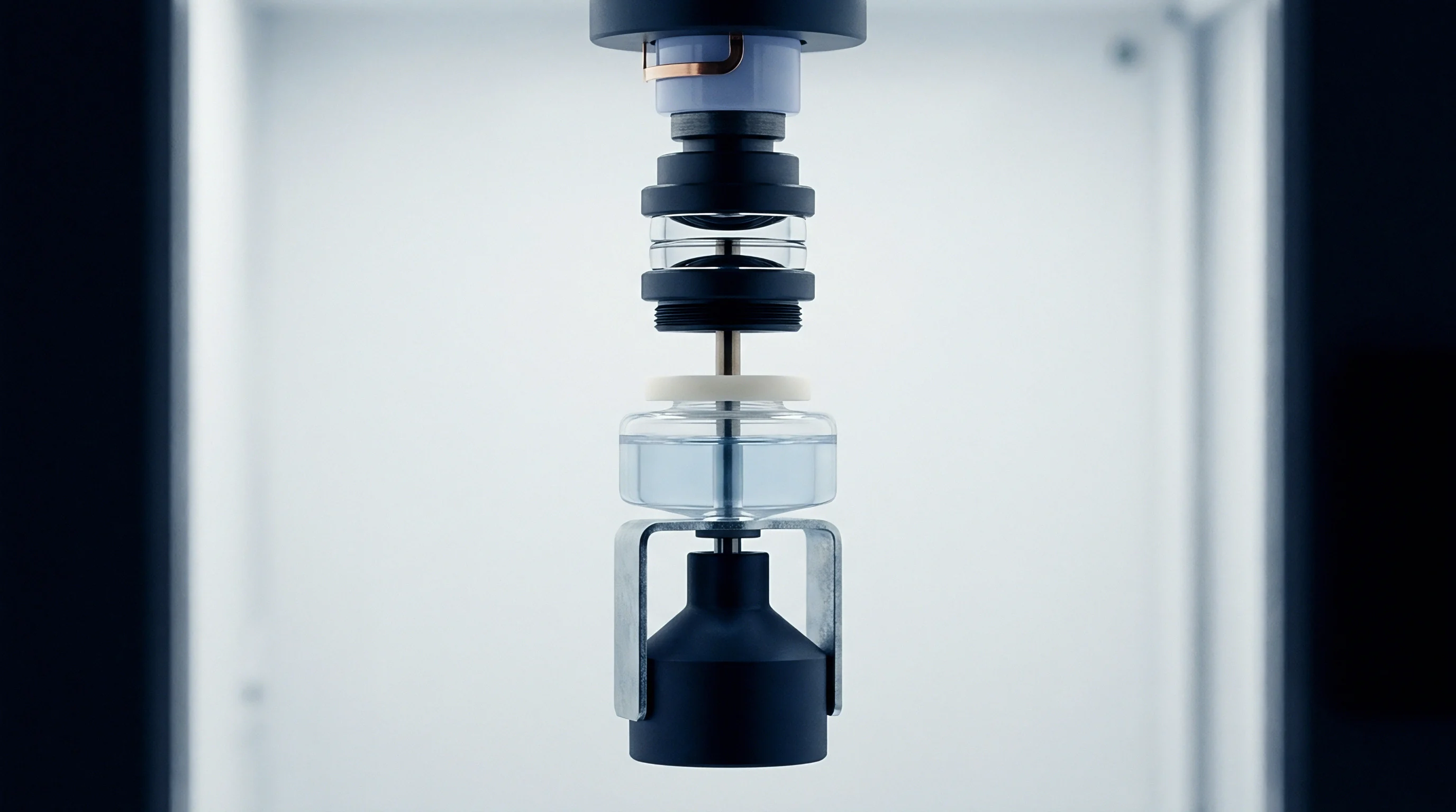

Soak
Exposing precision micro-sensors to sustained thermal dwell profiles isolates transient temperature gradient dynamics from true steady-state thermo-mechanical creep. Soak testing evaluates structural package integrity, adhesive outgassing, and stress relaxation behaviors under accelerated environmental conditions. Environmental chamber profiles must enforce extended dwell times to guarantee complete mechanical and thermal equilibrium across multi-material sensor packages.

Environmental Test Chamber Protocol Execution
Thermal stabilization rates depend on the thermal mass of the sensor assembly, circuit board thickness, and enclosure boundary conditions. Passive thermal soak profiles require dwelling at least 45 minutes at each target temperature plateau prior to taking calibration measurements. Rapid temperature ramps without adequate soak durations generate localized thermal gradients (nabla T), causing micro-machined frames to bow temporarily.
Thermal equilibrium requires sufficient dwell. Measurements taken during transient ramps distort calibration matrices, causing severe zero-acceleration offset errors when deployed in stable field environments.

Long Term Thermal Aging and Zero Shift Drift
Irreversible structural aging shifts baseline mechanical parameters over extended deployment periods. Polymeric die-attach materials undergo continuous micro-structural cross-linking and moisture desorption during operational life. These chemical shifts permanently alter the mechanical shear modulus (G) of the adhesive, shifting the mechanical neutral axis of the suspended MEMS mass.
Thermal aging tests conducted according to standardized environmental methods expose parts to +125circC for 1,000 continuous hours to evaluate long-term zero-g offset stability.
- Thermal Cycling Pre-Conditioning stabilizes internal packaging stresses through twenty complete cold-to-hot operational thermal ramps prior to baseline calibration.
- High Temperature Storage Burn-In accelerates polymer cross-linking and eliminates early-life structural creep mechanisms in die attach adhesives.
- Solder Joint Thermal Shock Testing verifies that printed circuit board mounting stress does not fracture hermetic package seal interfaces.
- Dynamic Thermal Gradient Characterization measures transient zero-offset spikes caused by directional heating sources located adjacent to the sensor.
Compliance with ISO 16063-21 thermal sweep qualification forces the exclusion of sensors exhibiting bias hysteresis exceeding fifty micro-g after five consecutive temperature ramps.
Standard qualification protocols like IEC 60068-2-14 define mandatory test structures for thermal evaluation, requiring specific dwell durations and ramp rates. Standard contracts for high-reliability inertial measurement units specify that maximum allowable zero-g bias thermal hysteresis shall not exceed 0.05 mg following continuous temperature cycling from -40circC to +85circC.

Supply
Selecting precision capacitive accelerometers requires balancing physical transduction stability against component cost, wafer fabrication maturity, and supply security. Silicon foundries producing MEMS capacitive elements rely on specialized deep reactive-ion etching (DRIE) and wafer-level bonding production lines. Wafer fabrication changes, die-attach epoxy formula substitutions, or mold compound revisions alter the thermo-mechanical stress environment of the sensor die.
Purchasing contracts must mandate advance Change Notification (PCN) agreements to prevent unannounced material changes that compromise zero-g bias stability.

Commercial Grade Selection and Wafer Fabrication Sourcing
Commercial consumer-grade accelerometers designed for mobile devices employ low-cost plastic QFN encapsulation and non-hermetic packaging topologies. These components exhibit thermo-mechanical zero-g bias drift between 200 μg/K and 1 mg/K, making them unsuitable for precision industrial inclination, structural monitoring, or tactical navigation applications. Automotive-qualified parts compliant with AEC-Q100 Grade 1 and AEC-Q103-001 mandate rigorous environmental testing, delivering bias stability figures under 100 μg/K. Precision tactical-grade sensors utilize hermetic ceramic packaging with internal stress-isolation structures, yielding zero-g bias thermal stability performance under 10 μg/K. Uncalibrated units show wide drift.

Second Source Qualification and Calibration Cost Economics
Achieving sub-milligal zero-g bias stability requires individual thermal calibration sweeps for every production unit. Multi-point temperature chamber calibration increases component testing time and capital equipment requirements dramatically. Calibration time drives module cost.
Factory thermal calibration steps account for up to 60 percent of the total manufactured unit cost in high-precision capacitive accelerometer modules.
Factory multi-point thermal calibration increases total packaged accelerometer test cost by up to three hundred percent relative to uncalibrated silicon.
Qualifying alternate supply sources for high-stability accelerometers requires extensive bench verification beyond standard datasheet parameter matching. Cross-qualifying an alternate component requires subjecting candidate parts to identical printed circuit board assembly processes, thermal shock profiles, and long-term aging trials. Differences in internal package die-attach compliance between two pin-compatible sensors can double thermal offset drift on identical board layouts, forcing complete re-validation of microprocessor temperature compensation tables.