Isolating Micromachined Accelerometer Zero Shift under Static Temperature Cycles
Isolating static thermal zero shift relies on decoupling mechanical die-attach strain relaxation from ASIC drift via extended static soak profile cycles.

Bond
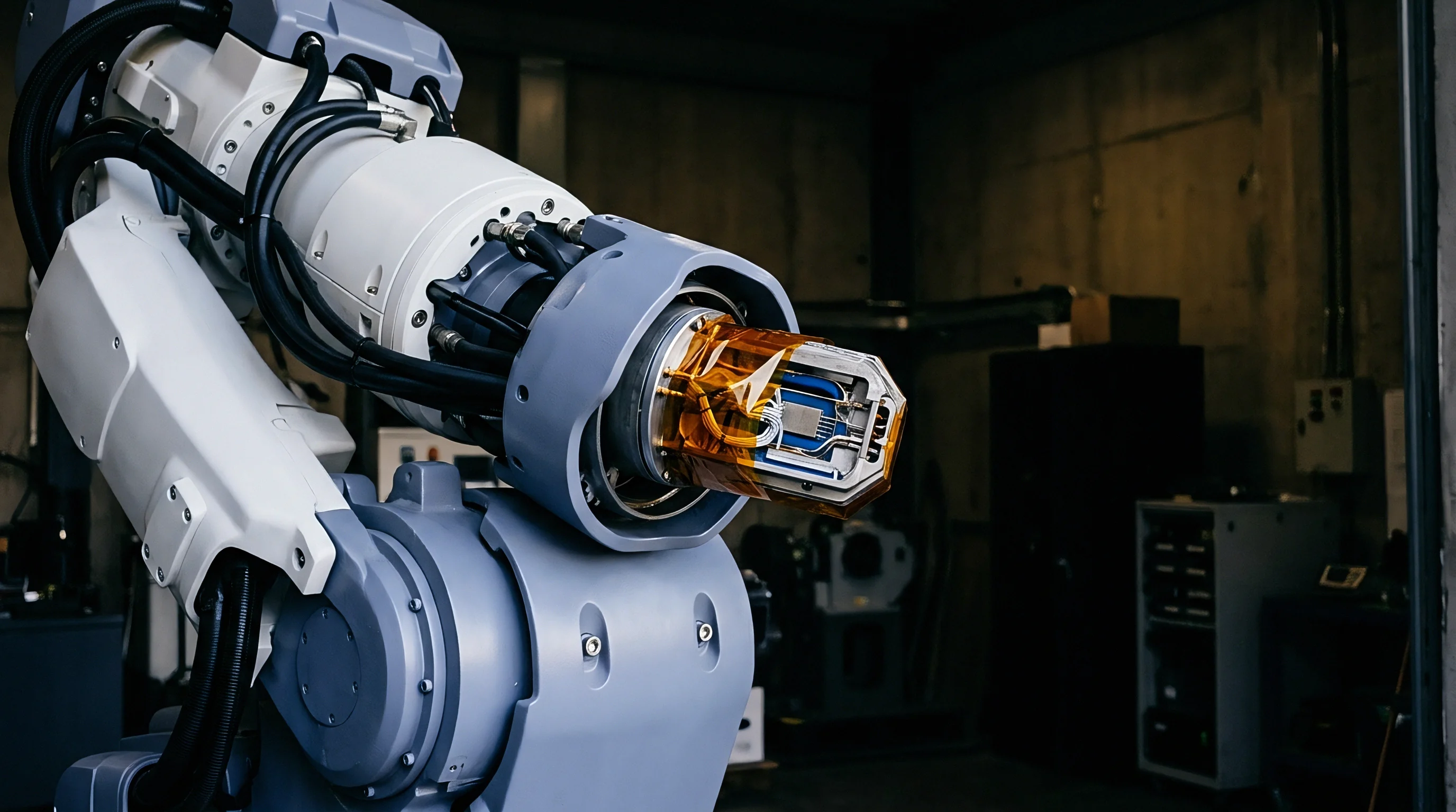
Interfacial joint mechanics between the micromachined silicon substrate and its carrier package dictate how thermal stress propagates into the capacitive micro-structure. Single-crystal silicon exhibits an isotropic coefficient of thermal expansion of 2.6 ppm/K at 25 degrees Celsius, whereas ceramic alumina substrates run at 6.5 ppm/K and organic printed circuit boards range from 13 to 17 ppm/K. Thermal cycling across a minus 40 to plus 125 degrees Celsius environmental envelope generates shear stress across the adhesive layer bonding the die to the package cavity. When the package contracts during cooling, residual strain transmits through the package floor directly into the micromachined anchor points supporting the suspended sense mass.
Because viscoelastic epoxy behaves differently from predictable silicon expansion, asymmetric mechanical strain deforms symmetric capacitive finger structures, altering differential sense capacitance independently of external acceleration. Differential capacitance changes as small as 0.1 femtofarads produce zero-acceleration offset shifts exceeding 5 millig in a standard 2 g full-scale sensor. Polymeric die-attach materials undergo continuous structural relaxation when held at elevated temperature plateaus, shifting the baseline strain state of the silicon anchor upon cooling back to ambient temperature.
| Die-Attach Material | Thermal Expansion Coefficient (ppm/K) | Elastic Modulus (GPa) | Glass Transition Temperature (°C) | Zero-Shift Hysteresis Impact (mg) |
|---|---|---|---|---|
| Eutectic AuSi Solder | 12.5 | 60.0 | N/A (Crystalline) | 0.3 to 0.8 |
| Silver-Filled Conductive Epoxy | 35.0 to 50.0 | 5.5 to 8.5 | 65 to 110 | 2.5 to 6.0 |
| Stress-Relief Silicone Adhesive | 180.0 to 300.0 | 0.002 to 0.010 | -120 to -50 | 0.8 to 1.8 |
| Glass-Frit Glass Bond | 6.8 to 7.2 | 40.0 | 420 | 0.1 to 0.4 |
High-modulus adhesives pass expansion mismatch forces directly into the anchor points. Eutectic gold-silicon bonds offer high mechanical rigidity but lack stress-buffering capacity, transferring substrate warpage straight to the sensing element. Low-modulus silicone adhesives absorb thermal mismatch strains to reduce absolute offset shift during temperature swings, though they introduce mechanical creep under sustained high-g shocks and allow outgassing within hermetically sealed cavities over extended operational lifespans.
Silver-filled epoxies fall between these modulus extremes, but permanent cross-linking density changes during thermal exposure cycles alter their elastic modulus over time.
Soft die-attach epoxies absorb assembly stress while hard eutectic bonds transfer ceramic expansion directly to the sense comb.
Glass-frit bonding applied at the wafer scale isolates the inner sense element inside a micro-cavity before dicing. Cap wafer integration creates a rigid localized mechanical boundary. External package forces must pass through the outer package epoxy, carrier substrate, cap solder, and cap wafer interface before reaching the internal suspended proof mass, diminishing package-induced strain through each structural boundary.
Non-linear hysteresis remains dominated by the bulk viscoelastic behavior of the die-attach paste chosen for second-level assembly.
Residual offset hysteresis stems from internal adhesive relaxation during factory burn-in rather than board-level solder stress.

Soak
Maintaining constant temperature plateaus across extended thermal profiles separates mechanical stress relaxation from transient thermal gradient shifts inside the MEMS cavity. Rapid thermal ramp profiles induce spatial temperature gradients across the sensor die, causing the integrated ASIC signal conditioner to heat faster than the suspended silicon proof mass. Temperature differences between the sense comb structure and the reference capacitors generate transient zero-g bias shifts that vanish once thermal equilibrium arrives.
Static thermal cycle testing decouples these transient thermal responses from permanent thermal zero-shift hysteresis.
Bench characterization profiles avoid dynamic ramps that mask hysteresis by using slow ramp rates below 0.5 degrees Celsius per minute coupled with dwell times of two to four hours at each target temperature plateau. Target plateaus established at minus 40, minus 20, zero, plus 25, plus 85, and plus 125 degrees Celsius allow the entire assembly to achieve thermal stabilization. Baseline zero-g offset voltage recorded at plus 25 degrees Celsius prior to thermal cycling provides the initial absolute reference, against which post-dwell readings at plus 25 degrees Celsius reveal irreversible thermal hysteresis.
Testing procedures reveal four primary failure modes responsible for non-repeatable zero-acceleration offsets under static thermal cycling profiles:
- Anchor strain relaxation occurs when polymer die-attach pastes undergo molecular rearrangement during sustained high-temperature dwells, altering the neutral mechanical position of the silicon proof mass.
- Glass-frit micro-cracking releases localized residual stress within wafer-level caps, shifting the capacitive gap distance between fixed and movable comb teeth permanently.
- Substrate thermal expansion creep deforms leadframe elements inside plastic overmolded packages, inducing structural bending across the die mount plane.
- ASIC reference voltage thermal drift alters the internal analog-to-digital converter reference independently of mechanical sense element changes, shifting reported acceleration counts.
Thermal cycling profiles that bypass static dwells blend transient package bowing with permanent material creep. A sensor subjected to a 10 degree Celsius per minute ramp rate exhibits transient zero shifts caused by the coefficient of thermal expansion differential between the silicon die top surface and the die backside attached to the substrate, as the front expands faster and induces temporary die curvature. Holding the assembly at a static temperature for two hours flattens the thermal gradient to isolate residual mechanical deformation, ensuring that offset deltas measured after reaching thermal equilibrium represent true material hysteresis.
A 0.5 millig zero-g offset shift remains after returning to 25 degrees Celsius following a static thermal dwell at 125 degrees Celsius for two hours.
The precise spatial distribution of micro-voids in conductive die-attach pastes that triggers irreversible zero-g baseline offset jumps after static hot dwells remains unquantified across high-volume production lots.

Bias
Zero-acceleration output stability across static thermal cycles limits the ultimate navigation grade precision achievable in micromachined accelerometers. An uncompensated zero-g offset error integrates over time into velocity and position errors in dead-reckoning algorithms. Dual-axis and tri-axial MEMS architectures combine spatial thermal sensitivity vectors that drift independently under static thermal cycling.
Mathematically isolating static zero shift requires quantifying both repeatable polynomial temperature coefficients and non-repeatable hysteretic residual errors.
Consider a capacitive micromachined accelerometer operating over a full-scale range of ±2 g with a nominal output sensitivity of 1000 mV/g. The device features an integrated analog-to-digital converter reporting acceleration in digital LSB counts, calibrated at 16,384 LSB/g with a nominal zero-acceleration output of 0 LSB at 25 degrees Celsius. The assembly undergoes a static thermal cycling evaluation inside an environmental test chamber mounted to an optical dividing head for precise gravity alignment.

Where Does Residual Hysteresis Originate in Calibrated ASIC Chains?
Integrated ASICs apply digital temperature compensation algorithms using on-chip diode temperature sensors. The output offset voltage follows a temperature-dependent function, where total zero-g offset drift as a function of static temperature includes a deterministic polynomial component and a hysteretic component:
V_offset(T) = V_0 + a_1 (T – T_ref) + a_2 (T – T_ref)^2 + a_3 (T – T_ref)^3 + H(T)
In this expression, V_0 represents baseline zero-g offset voltage at reference temperature T_ref of 25 degrees Celsius. Parameters a_1, a_2, and a_3 represent first, second, and third-order temperature coefficients stored in internal OTP EEPROM memory, while H(T) captures non-repeatable thermal hysteresis. During a heating cycle from minus 40 to plus 125 degrees Celsius, H(T) follows an upper branch curve H_up(T); during cooling back from plus 125 to minus 40 degrees Celsius, it follows a lower branch curve H_down(T).
| Compensation Polynomial Order | Deterministic Drift Reduction (%) | Peak Static Hysteresis Residual (mg) | EEPROM Memory Budget (Bytes) | ASIC Computation Time (µs) |
|---|---|---|---|---|
| Uncompensated Raw Die | 0.0 | 12.50 | 0 | 0 |
| 1st Order Linear (a1) | 78.5 | 3.20 | 4 | 1.2 |
| 2nd Order Quadratic (a1, a2) | 94.2 | 1.10 | 8 | 2.8 |
| 3rd Order Cubic (a1, a2, a3) | 98.7 | 0.45 | 12 | 4.5 |
| 4th Order Polynomial | 99.1 | 0.42 | 16 | 6.8 |
While higher-order polynomial functions fit deterministic non-linear thermal drift curves accurately, calibration cannot fix underlying hysteresis. Third-order polynomial models reduce deterministic thermal drift by 98.7 percent relative to raw die outputs, but residual peak offset error remains bounded by the maximum separation between H_up(T) and H_down(T). For an assembly exhibiting 0.45 millig peak residual hysteresis, third-order polynomial compensation leaves 0.45 millig of uncompensated non-repeatable offset error across the operating temperature window.
The mathematical evaluation of static thermal zero shift calculates the maximum absolute offset delta at room ambient temperature following thermal cycling:
Delta_Hysteresis = | V_offset_post(T_ref) – V_offset_pre(T_ref) | / Sensitivity
Assume an initial zero-g output reading of 12 LSB at 25 degrees Celsius prior to thermal exposure. Following a static thermal soak cycle reaching plus 125 degrees Celsius and returning to 25 degrees Celsius, the reading settles at 28 LSB, yielding a calculated zero shift delta of 16 LSB counts. Dividing 16 counts by the sensitivity of 16,384 LSB/g produces a static zero shift hysteresis of 0.976 millig ~ an offset change permanently stored in the structural strain state of the die assembly until thermal annealing occurs.
Compliance with AEC-Q100 Grade 3 thermal testing leaves uncompensated zero-g bias hysteresis unmonitored unless static dwell holds exceed four hours at each temperature plateau.
Under standard IEEE 1431 testing procedures, paragraph 6.2 specifies that zero-acceleration drift figures omit dynamic ramp data, forcing procurement specifications to isolate static thermal hysteresis separately from thermal transient response.

Layout
Board assembly geometries dictate the mechanical boundary conditions imposed on surface-mount sensor packages during thermal expansion. Printed circuit boards expand much faster than silicon or ceramic packages: standard FR-4 substrate material expands at 14 to 17 ppm/K in the X and Y axes, while expanding up to 60 ppm/K in the Z axis. Reflow soldering creates a rigid mechanical joint between package metallized pads and PCB copper lands at the liquidus-to-solidus transition temperature of solder.
As the assembled board cools to room ambient, thermal expansion mismatch locks mechanical stress into the sensor package leads.
Asymmetric solder fillets pull sensor package edges unevenly, creating localized twisting moments, while bending moments applied to leadless chip carrier packages transfer shear forces through the substrate to internal silicon die anchors. Placing heavy components, large heat sinks, or mounting screws adjacent to the sensor package amplifies mechanical strain during operational temperature shifts. Designing isolation structures into the circuit layout dampens this mechanical stress propagation from the main board assembly.
Board-level mechanical isolation techniques rely on specific geometry choices to decouple package footprints from PCB thermal movement:
- Perimeter isolation slots cut through the PCB laminate surrounding the sensor footprint reduce mechanical stress transmission from adjacent board sections by up to 80 percent.
- Symmetrical trace routing ensures balanced thermal mass and mechanical anchor stiffness across opposing package solder pads during reflow cooling.
- Component placement orientation aligns the sensitive axis of the sensor parallel to the axis of minimal PCB flexure during thermal expansion.
- Solder mask expansion clearance prevents uneven solder wetting heights across package terminals, suppressing asymmetric tilt moments.
Potting compounds used for environmental encapsulation introduce severe mechanical stress during static thermal cycling profiles. Rigid polyurethane and epoxy encapsulants exhibit high thermal expansion coefficients ranging from 40 to 100 ppm/K below their glass transition temperatures, escalating up to 180 ppm/K above glass transition. Encapsulants fill package under-die clearance gaps, locking the package to the substrate.
Thermal cycling causes the potting resin to expand against package walls, generating multi-axis compressive loads that alter baseline zero-g offset calibration by more than 15 millig. Soft silicone gels or compliant conformal coatings preserve package strain isolation.
Solder reflow peak temperatures alter the baseline zero-g offset calibration performed at the sensor foundry.
Mounting a sensor die adjacent to high-power dissipation components degrades zero-acceleration stability regardless of internal ASIC compensation algorithms.
Dossier
Component qualification protocols define the incoming inspection criteria necessary to catch lot-to-lot die-attach variability before surface mounting. Foundry datasheets report typical zero-g temperature coefficients measured on loose components inside specialized test sockets that exert no mechanical solder stress on package leads. A component boasting a zero-g thermal offset drift specification of 0.2 mg/K on its datasheet frequently demonstrates thermal hysteresis exceeding 2.0 mg/K once surface-mounted to an FR-4 assembly.
Sourcing specifications must mandate static thermal cycle screening protocols on board-mounted samples to establish true production yield limits.
Standard automotive qualification procedures under AEC-Q100 Grade 1 evaluate components across a minus 40 to plus 125 degrees Celsius operating ambient window, but focus on catastrophic operational life failure rates rather than precision zero-shift hysteresis limits. Procurement engineering documentation must append custom parametric rejection thresholds governing post-thermal-cycle zero-g offset drift. Screening 100 percent of production sensors through a rapid thermal burn-in profile identifies infant mortality failures, but isolating die-attach creep outliers requires multi-hour static dwells.
Evaluating incoming component lots follows a structured static thermal cycle verification sequence:
- Place incoming sensor packages into an environmental chamber at ambient room temperature.
- Ramp the temperature to the maximum storage limit at a controlled rate of one degree per minute.
- Maintain static temperature plateau for four hours to complete internal mechanical strain relaxation.
- Cool the chamber to room ambient temperature and record zero-acceleration output voltages across all axes.
- Compute baseline offset delta against factory calibration records to reject outlier die-attach lots.
| Package Architecture | Hermeticity | Board-Level Hysteresis (mg) | Relative Unit Cost Index | Dominant Failure Mode |
|---|---|---|---|---|
| Plastic Overmolded LGA (3×3 mm) | Non-Hermetic | 1.5 to 4.5 | 1.0 | Mold Compound Viscoelastic Creep |
| Premolded Cavity LGA (3×3 mm) | Non-Hermetic | 0.8 to 2.2 | 1.4 | Die-Attach Epoxy Relaxation |
| Hermetic Ceramic LCC (5×5 mm) | Hermetic (He Leak Test) | 0.2 to 0.6 | 3.8 | Substrate Solder Joint Shear Stress |
| Wafer-Level Chip-Scale (WLCSP) | Wafer-Scale Cavity | 0.5 to 1.2 | 2.1 | Direct Bump Solder Thermal Mismatch |
Selecting plastic overmolded packages minimizes landed component costs while increasing vulnerability to moisture absorption and mold compound thermal relaxation. Moisture trapped within non-hermetic plastic packages expands during thermal cycling, altering package internal stress distributions unpredictably. Ceramic leadless chip carrier packages seal the die cavity hermetically in dry nitrogen, eliminating moisture-induced offset drift.
Although ceramic construction increases unit purchasing costs by roughly four-fold compared to plastic overmolded equivalents, the expenditure yields a multi-fold reduction in uncompensable thermal zero-shift hysteresis.
Skimping on multi-point static thermal screening allows unstable die-attach lots into assembly, causing field recalibration costs that exceed component unit savings by two orders of magnitude.