Calculating Thermal Zero Offset Hysteresis Error Budgets in Structural Leveling
Thermal hysteresis error budgets require separating structural tilt from sensor package thermomechanical strain using dual-ramp chamber calibration data.


Tilt
Measuring structural inclination in long-span bridges and foundation slabs depends on transducer zero stability across diurnal temperature swings. When ambient temperatures fluctuate between minus twenty degrees Celsius and sixty degrees Celsius, monitoring systems face zero-point shifts that look identical to actual physical movement. Gravimetric sensors convert tilt angles into electrical signals via internal reference masses, fluid levels, or optical beams, where even minor thermal expansion inside the sensing element shifts mechanical baseline alignment without any change in structural geometry.
Thermal zero offset drift falls into two distinct categories: deterministic thermal drift and hysteretic zero shift. Deterministic drift follows a repeatable curve that digital signal processors can correct with polynomial temperature equations. Hysteretic zero shift, however, is path-dependent; the transducer output varies with temperature history, heating direction, and cooling rate.
Uncompensated thermal hysteresis introduces false readings that quickly corrupt error budgets in structural leveling.

Transducer Physics across Thermal Gradients
Electrolytic tilt sensors, capacitive MEMS cells, and optical pendulums convert gravitational acceleration into electronic signals through fundamentally different mechanisms. Electrolytic sensors measure impedance changes across fluid cavities as conductive liquid moves across excitation electrodes. Because fluid viscosity drops as temperature rises, internal damping ratios and the meniscus shape change accordingly, while thermal expansion of the housing alters electrode immersion depth to shift the zero balance.
Capacitive micro-electro-mechanical systems rely on micromachined silicon proof masses suspended by flexible tether beams. Temperature changes induce thermal stress in these suspension springs, and spatial temperature gradients across the silicon die distort tether symmetry to create differential capacitance changes between opposing electrodes. Because the sensing elements lag ambient conditions, internal differential expansion between the silicon die, glass frit substrate, and ceramic carrier forces asymmetric mechanical stress directly into the suspension anchors.
| Transduction Principle | Primary Hysteresis Source | Typical Zero Offset Hysteresis (µrad) | Thermal Recovery Time (min) |
|---|---|---|---|
| Capacitive MEMS | Die-attach stress and gel relaxation | 25 to 80 | 45 |
| Electrolytic Fluid | Fluid meniscus surface tension hysteresis | 10 to 35 | 120 |
| Optical Pendulum | Housing structural thermal warping | 5 to 15 | 15 |
| Force-Balanced Servo | Flexure hinge thermomechanical memory | 2 to 8 | 30 |
Packaging Strain and Thermomechanical Offset
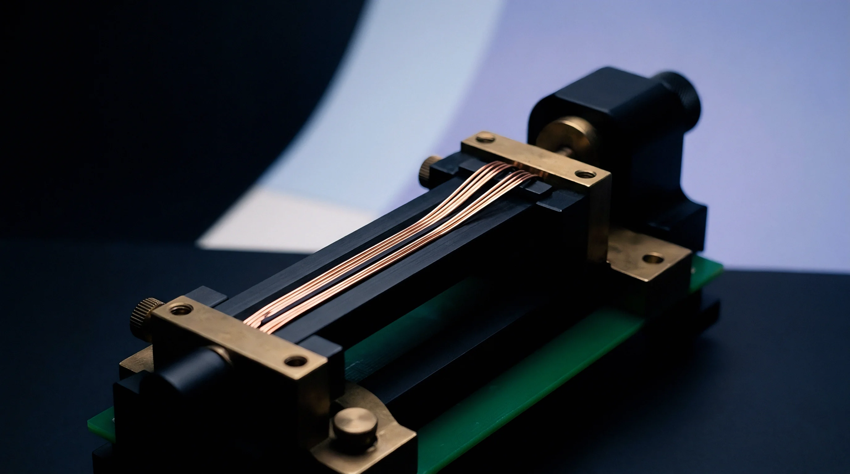
Mismatched expansion coefficients between silicon dies, ceramic substrates, and aluminum housings generate internal stress during thermal cycles. Silicon carries a coefficient of thermal expansion near two point six parts per million per Kelvin, compared to six point five for ceramic carriers and twenty-three for aluminum enclosures. As ambient temperatures shift, these material disparities generate mechanical bending moments across the sensor assembly.
Internal structural distortion from package strain flexes the substrate surface, causing micro-radian shifts in sensing axis orientation relative to external mounting pads. Gel encapsulation compounds placed over MEMS dies to damp mechanical vibration absorb thermo-elastic stress; as temperature drops, gel stiffness increases, locking in mechanical stress that releases only slowly over several hours. Datasheet specifications routinely attribute residual offset shifts to external mounting distortion rather than internal sensor housing thermal memory.


Hysteresis
Reversible thermal zero shifts follow deterministic polynomial temperature curves, whereas non-reversible baseline shifts trace path-dependent loops across heating and cooling phases. In structural leveling applications, measuring tilt to micro-radian accuracy requires separating linear and quadratic thermal drift from hysteretic residual errors. When ambient temperature rises during daylight hours and falls at night, a sensor’s zero output at twenty degrees Celsius while warming will not match its output at twenty degrees Celsius while cooling.
Hysteresis distorts static calibration through internal mechanical friction, structural relaxation of die-attach adhesives, and visco-elastic gel behavior. Semiautimated structural leveling platforms operating in environments with thirty degree Celsius daily temperature variations accumulate uncompensated zero shifts. Over repeated thermal cycles, hysteretic loops create progressive baseline uncertainty that invalidates simple single-variable compensation lookup tables.

Path Dependency in Temperature Ramping
Heating a sensor from minus twenty degrees Celsius to sixty degrees Celsius produces a different offset trajectory than cooling the same device over the same range. Plotting output against temperature reveals a closed hysteresis loop formed by this directional difference. Peak loop width typically occurs near the midpoint of the operating thermal range, where internal thermal gradients reach maximum levels.
Spatial temperature distribution inside the sensor housing drives this directional asymmetry. During rapid ambient heating, outer aluminum housing structures expand faster than internal glass-passivated silicon dies. Thermal conduction delays across internal air gaps and potting layers create dynamic spatial temperature differentials exceeding five degrees Celsius between internal components, and when cooling reverses these internal gradients, mechanical bending moments shift across die anchors.
Dual-ramp thermal calibration from minus twenty to sixty degrees Celsius isolates hysteretic zero offset bands down to fifteen microradians.
Silicone Gel and Adhesive Creep
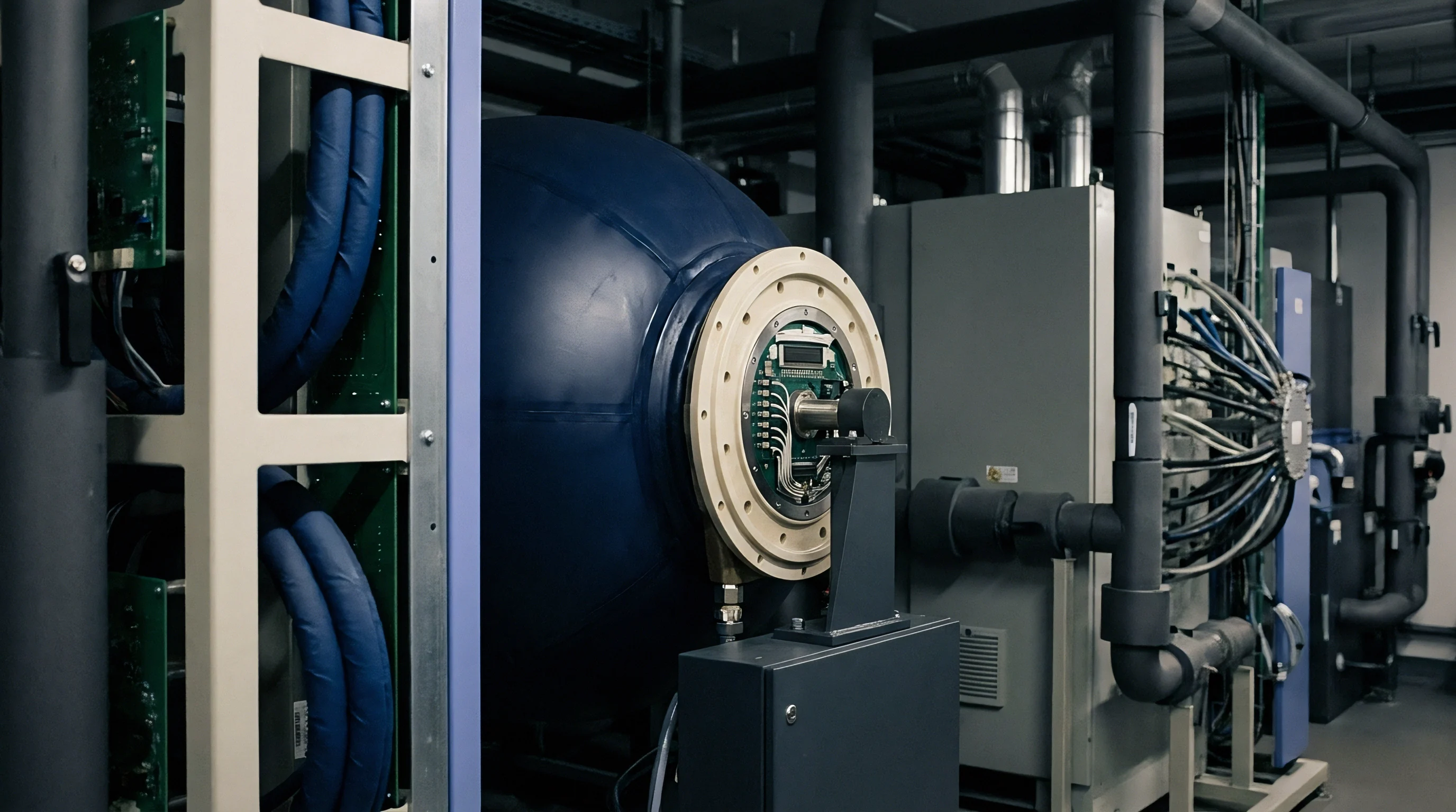
Encapsulation compounds inside MEMS cavities absorb mechanical stress during temperature transitions and relax over extended timeframes. Silicone gels protect fine wire bonds from moisture and structural shock while introducing visco-elastic damping. However, the storage modulus of these gels changes non-linearly across industrial operating temperatures; at sub-zero levels, glass transition phase shifts increase gel shear modulus by up to two orders of magnitude.
Die-attach epoxy layers holding silicon substrates to ceramic packages undergo mechanical relaxation under continuous strain. As temperature changes, thermal expansion mismatches force the epoxy bond line into shear deformation. These visco-elastic polymers exhibit strain relaxation lag, slowly recovering physical alignment over multiple hours following a rapid temperature step, so that any unrecovered strain appears as an equivalent tilt input to signal conditioning electronics.
- Package thermal stress asymmetry creates false structural baseline shifts during rapid ambient temperature swings.
- Encapsulation gel relaxation delay induces lingering zero offsets after temporary thermal extremes.
- Mounting plate thermal warping introduces mechanical torque that mimics structural inclination changes.
- Internal printed circuit bow alters capacitive element alignment relative to the gravitational vector.
Uncorrected hysteretic zero shifts lead directly to false structural movement alarms and costly emergency inspection dispatches.

Arithmetic
Quantifying total error budgets for precision level monitoring demands combining static thermal coefficient terms with path-dependent thermal loop bounds. Standard industrial sensor datasheets publish zero temperature coefficients as linear slopes expressed in arcseconds or micro-radians per degree Celsius. Relying solely on these linear coefficients understates measurement error by ignoring non-linear residual polynomial fitting errors and thermal zero hysteresis loop width.
Mathematical modeling of thermal zero offset hysteresis combines deterministic thermal drift polynomials with bounded hysteretic deviation terms. Deterministic drift is modeled using a third-order polynomial equation, while path-dependent hysteresis adds an uncertainty envelope function scaled by peak temperature delta and rate of thermal change. Calculating total error bounds requires establishing statistical limits for each component under operational environmental conditions.
Root Sum Square versus Worst Case Summation
Combining independent sensor tolerances using standard statistical quadrature assumes zero correlation between individual error terms. A root-sum-square formulation models random, uncorrelated errors like electronic amplifier noise and analog-to-digital converter quantization. However, thermal zero hysteresis errors correlate strongly with ambient daily temperature cycles, so assuming independence between thermal zero slope drift and thermal hysteresis underestimates total system error.
Worst-case summation adds absolute error magnitudes directly, defining deterministic boundaries for safety-critical leveling applications, whereas root-sum-square summation provides realistic operational confidence limits for multi-sensor monitoring arrays. Evaluating a structural leveling subsystem operating across a sixty Kelvin thermal range demands calculating both total worst-case arithmetic bounds and root-sum-square statistical estimates.
Thermal hysteresis loop width scales directly with package mass asymmetry and substrate thermal expansion mismatch.

Where Does Package Thermal Asymmetry Override MEMS Element Compensation?
Internal thermal gradients across multi-axis sensor arrays break standard digital polynomial correction models when external temperature changes exceed two degrees per minute. Consider a precision leveling application requiring structural tilt monitoring within a fifty micro-radian total error budget across a temperature range from minus ten degrees Celsius to plus fifty degrees Celsius. A dual-axis capacitive MEMS inclinometer is selected with a published linear thermal zero coefficient of five micro-radians per Kelvin.
Third-order polynomial fitting leaves a residual uncompensated polynomial error of twelve micro-radians. Environmental chamber dual-ramp testing reveals a thermal zero offset hysteresis loop width of twenty-five micro-radians across the sixty Kelvin thermal span, while mechanical mounting strain adds an estimated eight micro-radians of tilt error.
Calculating worst-case thermal zero offset error sum requires combining uncompensated linear residual, hysteresis loop width, and mounting distortion:
E_worst = E_residual + H_zero + E_mounting
E_worst = 12 µrad + 25 µrad + 8 µrad = 45 µrad
Calculating statistical root sum square thermal error yields:
E_rss = sqrt( (12 µrad)^2 + (25 µrad)^2 + (8 µrad)^2 ) = sqrt( 144 + 625 + 64 ) = sqrt( 833 ) = 28.86 µrad
Comparing these results against the fifty micro-radian accuracy budget demonstrates that thermal zero offset hysteresis accounts for fifty-five percent of the total allowable error envelope. Neglecting the twenty-five micro-radian hysteresis term produces a misleading root-sum-square calculation of fourteen point four micro-radians, risking system failure when ambient temperatures undergo cyclic diurnal shifts.
- Determine maximum diurnal temperature delta to set the physical boundary for full-scale thermal offset calculations.
- Extract sensor polynomial residual error from primary calibration certificates to establish baseline non-linearity limits.
- Measure peak hysteresis loop width across dual directional thermal ramps in an environmental chamber.
- Calculate total root sum square error by combining uncompensated thermal slope, residual loop width, and mounting distortion.
Applying these mathematical envelope bounds allows engineers to establish real-world structural leveling thresholds that remain robust against environmental temperature fluctuations.

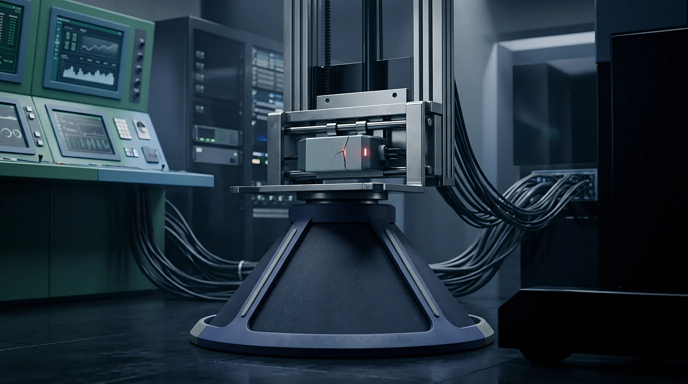
Chamber
Testing thermal profiles for tilt transducers demands controlled environmental enclosures capable of precise ramp rates and multi-axis baseline tracking. Environmental chambers used for sensor characterization require spatial temperature uniformity within zero point two degrees Celsius. Gravimetric reference mounts positioned inside the chamber require structural isolation from compressor vibration; granite mounting benches resting on passive air isolation dampers prevent structural vibration from corrupting the noise floor.
Standard characterization tests expose sensors to dual directional thermal sweeps while holding the transducer fixed against a true horizontal granite reference plate. Recording output readings at discrete temperature steps during both increasing and decreasing ramps maps full zero offset hysteresis loops. Gathering empirical data across multiple thermal cycles isolates structural memory, clarifying baseline recovery performance after exposure to maximum storage temperature limits.
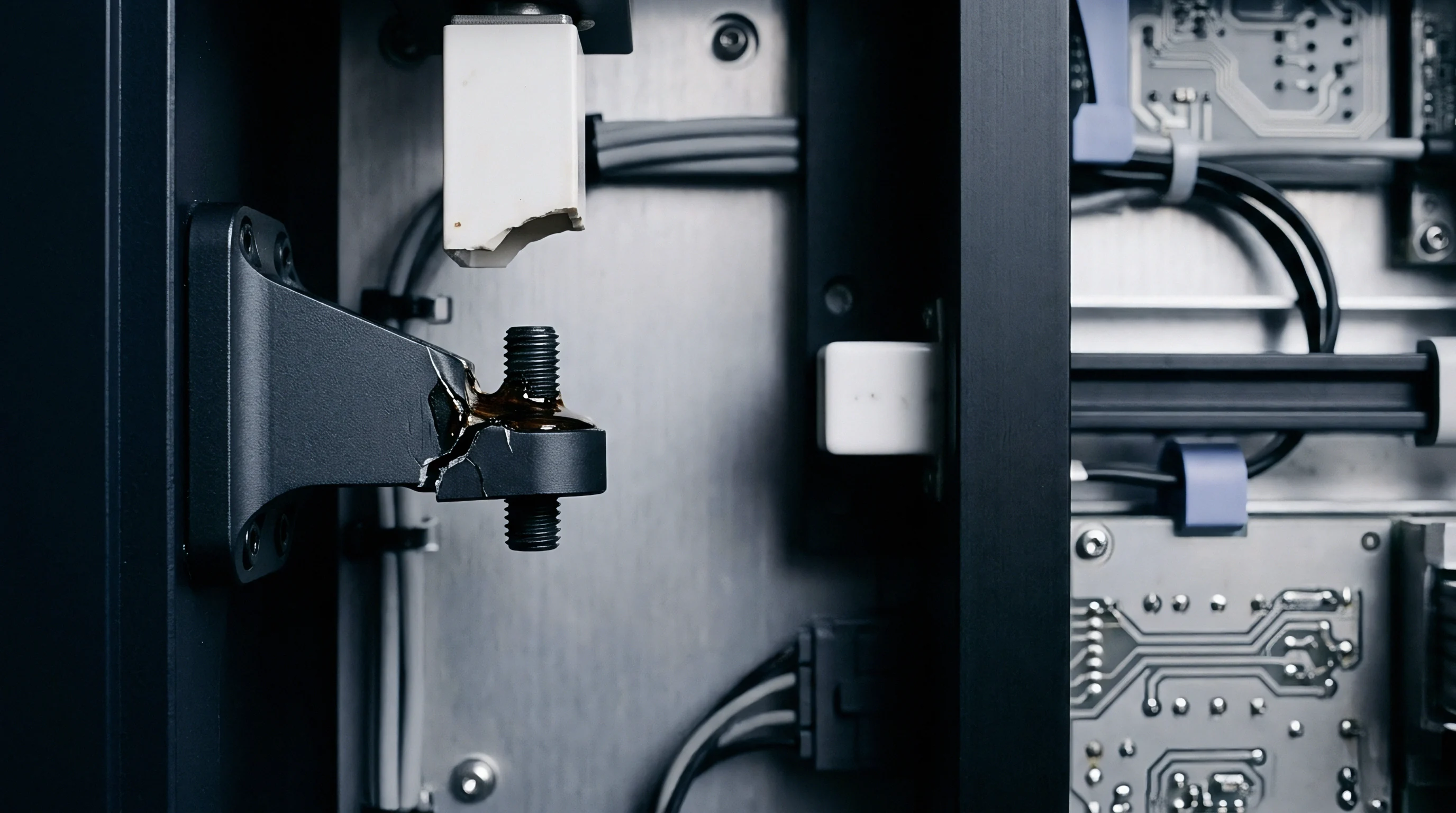
Thermal Ramp Rates and Soak Times
Characterizing path-dependent offset behavior demands slow temperature variations around zero point five degrees Celsius per minute to separate spatial temperature gradients from material relaxation. Ramp rates exceeding two degrees Celsius per minute introduce dynamic thermal gradient errors that distort physical hysteresis measurements. Dynamic spatial gradients vanish once internal equilibrium is reached, whereas true hysteretic structural memory persists after ambient stabilization.
Adequate soak duration at peak temperature limits guarantees complete thermal stabilization of internal sensor packaging components. Soaking transducers for four hours at minimum and maximum target temperatures ensures visco-elastic encapsulation gels reach mechanical strain equilibrium. Standard environmental testing protocols execute three consecutive full-range thermal cycles to stabilize structural stress history before capturing calibration data.
| Sensor Architecture | Ramp Rate (°C/min) | Soak Duration (hr) | Maximum Offset Hysteresis (µrad) | Recovery Delta after 24h (µrad) |
|---|---|---|---|---|
| Dual-Die Hermetic Ceramic | 0.5 | 4.0 | 12.4 | 1.2 |
| Single-Die Molded Plastic | 0.5 | 4.0 | 68.5 | 14.8 |
| LCC Surface Mount Gel-Filled | 0.5 | 4.0 | 42.1 | 8.3 |
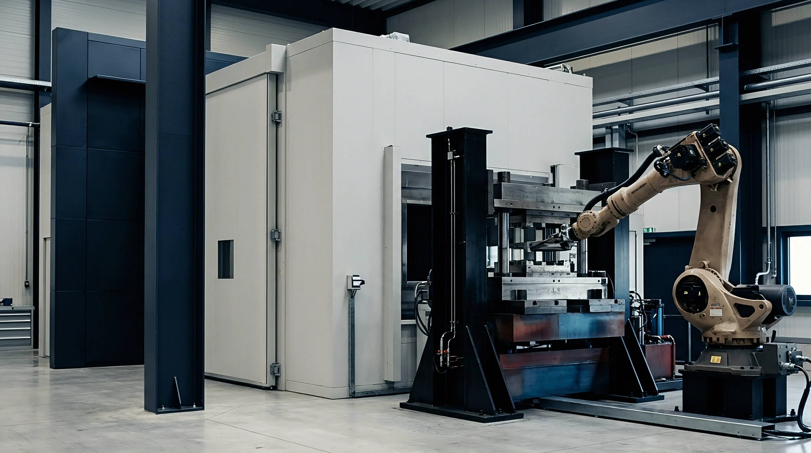
Distinguishing Reversible Drift from Hysteretic Memory
Plotting sensor output voltage against ambient temperature during continuous thermal cycling reveals whether baseline shifts return to origin after equilibrium. Reversible thermal drift yields overlapping data traces during repeated heating and cooling legs, while path-dependent hysteresis produces distinct, separable output tracks enclosing a measurable loop area. Non-reversible structural settling appears as a continuous baseline drift between consecutive thermal cycles.
Calibration software processing dual-ramp characterization data separates static polynomial zero drift from directional hysteresis bounds. Temperature lookup tables operating inside high-resolution digital signal processors store distinct forward and reverse compensation coefficients based on the sign of the measured temperature rate of change. Measuring instantaneous temperature gradient vectors enables active real-time compensation for dynamic internal package thermal stress.
Compliance with IEC 60068 2 14 thermal ramp testing standards prevents uncharacterized zero offset drift from invalidating long-term structural monitoring data.
- Mount the tilt transducer on an optically flat granite surface inside the thermal enclosure using specified operational torque limits.
- Stabilize the ambient enclosure temperature at twenty degrees Celsius for two hours to record baseline gravimetric zero output.
- Ramp temperature down to minus twenty degrees Celsius at zero point five degrees per minute and hold soak for four hours.
- Increase temperature to sixty degrees Celsius at the identical ramp rate and hold soak for four hours before returning to initial baseline.
Whether long-term material aging inside MEMS suspension springs gradually alters the hysteresis envelope over ten years of operational field deployment remains an open question in structural health monitoring.


Contract
Procurement documents for high-precision structural leveling systems specify explicit thermal hysteresis acceptance testing parameters rather than relying on generic manufacturer datasheet zero temperature coefficients. Sensor datasheets frequently omit path-dependent offset performance, publishing only typical linear temperature drift figures recorded under static room temperature conditions. Procurement engineers writing component acceptance specifications include defined environmental chamber dual-ramp test methods with absolute pass and fail thresholds for zero offset hysteresis loop width.
Sourcing precision inclinometers requires establishing contractual guarantees covering full-scale operating temperature ranges, linking payment milestones directly to incoming inspection batch testing results. Structural monitoring projects using hundreds of tilt sensors depend on high component-to-component repeatability. Specifying strict zero hysteresis limits prevents low-cost consumer-grade sensor assemblies from corrupting civil engineering leveling measurements.

Datasheet Ambiguities and Supplier Specifications
Commercial sensor documentation routinely lists thermal zero shift in parts per million per degree Celsius while omitting path-dependent directional error figures. Standard parameter tables highlight impressive resolution and low noise density while obscuring zero offset thermal hysteresis under vague footnotes. These footnotes often state that zero offset specifications apply only after thermal equilibrium is reached, ignoring real-world field conditions where ambient structural temperatures fluctuate continuously.
Comparing sensor vendors requires demanding full dual-ramp temperature sweep calibration certificates for individual serialized parts. High-performance sensor manufacturers supply digital calibration files containing full temperature cycle characterization data. Contractual terms should specify supplier financial responsibility for recalibration expenses if component lot testing reveals thermal zero offset hysteresis exceeding contracted micro-radian boundaries.
| Subsystem Component | Maximum Thermal Zero Offset (µrad) | Hysteresis Allowance (µrad) | Target Landed Cost (USD) | Qualification Standard |
|---|---|---|---|---|
| Primary Structural Inclinometer | 20.0 | 10.0 | 450.00 | IEC 60068-2-14 |
| Secondary Reference Inclinometer | 50.0 | 25.0 | 180.00 | AEC-Q103-001 |
| Auxiliary Level Switch Array | 150.0 | 60.0 | 65.00 | ISO 16063-16 |

Verification Clauses and Acceptance Criteria
Incoming inspection for critical civil infrastructure tilt monitoring involves batch testing inside calibrated thermal enclosures before jobsite installation. Sample testing protocols typically select ten percent of each incoming component shipment for full dual-ramp environmental chamber evaluation. Test clauses specify that if any single sample sensor fails thermal zero offset hysteresis limits, the entire shipment batch faces rejection or hundred percent screening at the supplier’s expense.
Contract language must define exact mounting fixtures, electrical excitation voltages, and thermal ramp parameters for incoming quality audit testing. Standardizing these test conditions prevents supplier disputes regarding methodology, while calibration verification requirements compel vendors to lock down packaging supply chains ~ preventing unannounced changes to internal die-attach epoxies or encapsulation compounds that alter thermal hysteresis performance.
Specifying dual directional thermal ramp testing in component procurement specifications eliminates unbudgeted tilt measurement errors during field commissioning.
Incorporating ISO 16063 transducer calibration standards directly into sensor supply agreements forces manufacturers to guarantee zero offset hysteresis limits across full operational ambient temperature ranges.