Dynamic Thermal Gradient Uncertainty Budgets for Field Transfer Standards Verification
Dynamic thermal gradients in field transfer standards expand calibration uncertainty, requiring calculated ramp lag and axial conduction additions.


Gradient
Field calibrators operating in real plant environments rarely achieve static thermal equilibrium. Portable dry-well calibrators, micro-baths, and surface calibration plates undergo rapid temperature transitions to minimize technician downtime during calibration routes. During a temperature ramp, internal heating elements apply localized thermal flux to the insert block, generating significant spatial temperature differences along the axial and radial axes of the calibration zone.
Metal insert blocks inside portable calibrators experience non-uniform temperature profiles during heating or cooling. Heat flows through the metallic block body via conduction while heat dissipates at the top and bottom through radiation and ambient convection. These competing thermal transfers construct severe vertical temperature gradients.
An axial gradient represents a spatial temperature variance along the vertical axis of the insert well where reference standards and sensors under test reside.
A dry block calibrator running a 2.0 K per minute ramp exhibits an axial gradient of 0.180 K across a 40 mm immersion zone.
Radial gradients occur between adjacent wells in multi-hole calibrator blocks. When a high-wattage cartridge heater ramps up, outer well positions absorb thermal flux faster than central wells. The temperature difference between reference probes and adjacent units under test expands dramatically during continuous thermal transitions.
Static calibration certificates issued by accredited laboratories report axial and radial uniformity under stabilized, zero-ramp equilibrium. Applying those static figures to dynamic field calibration introduces uncounted systematic errors into the verification process.

Transient Spatial Gradients in Dry Wells
Block profiles shift during ramps. When a dry block calibrator transitions from ambient to 300 degrees Celsius at its maximum ramp rate, internal control thermocouples register the target temperature long before the metal mass reaches steady-state distribution. Heat pipe designs and high-conductivity copper-alloy insert blocks mitigate but do not eliminate this transient spatial divergence.
An axial gradient across a standard 40 millimeter active zone of a industrial Platinum Resistance Thermometer (PRT) changes continuously during heating. Internal temperature profiles inside the insert well bow upward or downward depending on the direction of the ramp. During a heating cycle, the bottom of the well leads the top by several tenths of a Kelvin.
During a cooling cycle, the top of the block cools faster due to convective air currents, reversing the gradient direction.
| Calibrator Architecture | Operating Mode | Ramp Rate (K/min) | Axial Gradient (mK/cm) | Radial Gradient (mK) |
|---|---|---|---|---|
| Metallic Dry Block (Aluminum Alloy) | Static Equilibrium | 0.0 | 12.5 | 8.0 |
| Metallic Dry Block (Aluminum Alloy) | Dynamic Heating Sweep | 2.0 | 45.0 | 28.0 |
| Metallic Dry Block (Aluminum Alloy) | Fast Thermal Ramp | 5.0 | 112.0 | 64.0 |
| Fluidized Liquid Micro-Bath | Static Equilibrium | 0.0 | 3.5 | 2.0 |
| Fluidized Liquid Micro-Bath | Dynamic Heating Sweep | 2.0 | 14.0 | 9.5 |

Heat Sink Loading and Axial Drift
Inserting a cold probe into a preheated calibration well alters the internal energy distribution. The thermal mass of heavy industrial thermowells acts as a localized heat sink, pulling energy away from the block core. Heat flows along the sheath.
This localized heat drain deepens axial gradients in the immediate vicinity of the active sensing element.
Solid metal sheaths extract heat from the dry-well zone faster than thin ceramic reference probes. The resulting temperature depression creates a localized dynamic offset between the reference sensor display and the unit under test. Standard static calibration models assume heat loss through the stem remains constant.
In dynamic field operation, stem conduction varies continuously as the temperature difference between the insert block and the ambient atmosphere changes.
Suppliers frequently claim that internal digital filtering algorithms eliminate block non-uniformities, asserting that display stabilization guarantees spatial equilibrium across all insert wells.


Immersion
Probe depth inside a calibration well directly dictates how effectively heat transfers into the sensing element. Inadequate immersion depth causes stem conduction error, where ambient room temperature conducts down the sensor sheath and alters the internal junction reading. Stem conduction drains calibration accuracy.
Metal sheaths conduct energy away from the active sensor junction toward the cooler exterior ambient air. The magnitude of stem loss scales with sheath thermal conductivity, wall thickness, and outer diameter. When a transfer standard probe operates in a dynamic thermal field, stem conduction losses do not remain static.
The rapid change in block temperature creates a shifting temperature gradient along the submerged stem, changing the net heat loss rate at the sensing junction.
Immersion depth calculations rely on the physical properties of the probe sheath and the surrounding heat transfer medium. Standard rules derived from static heat transfer require an immersion depth equal to fifteen times the probe sheath diameter plus the length of the internal sensing element. Dynamic thermal transitions increase this requirement.
Thermal mass drives measurement lag.

Stem Loss under Rapid Thermal Transitions
Air pockets increase thermal resistance. The boundary resistance between the dry-well insert wall and the outer sheath of the probe creates a thermal delay. During rapid heating, heat energy must pass through the air gap, through the metal sheath, through internal insulating powder, and finally into the platinum element wire.
Stem loss non-equilibrium develops when heat drains out through the upper exposed stem faster than energy can penetrate the internal ceramic core. This effect creates a persistent negative bias in heating sweeps and a positive bias during cooling sweeps. Precision field verification protocols must account for stem conduction error as a transient dynamic variable rather than a fixed offset.
- Stem Loss Non-Equilibrium occurs when heat drains through exposed sheath metal faster than radial heat input can recharge the active sensing zone.
- Thermal Time Constant Divergence emerges from unequal mass distributions between ceramic-insulated reference probes and heavy industrial transmitter assemblies.
- Air Gap Boundary Resistance restricts heat flux across the air space separating the insert well wall from the outer sensor protective sheath.
- Axial Conduction Asymmetry distorts the vertical thermal profile during non-steady heating and cooling phases inside calibration blocks.

Thermal Response Mismatch between Reference and Target
Varying physical dimensions between a standard PRT and an industrial sensor generate unequal delay times during temperature sweeps. A small secondary reference PRT with a three-millimeter sheath diameter responds quickly to block temperature shifts. An industrial temperature transmitter housing a six-millimeter probe enclosed in a heavy thermowell responds slowly.
Sensor geometry dictates time response. The physical response difference creates a dynamic temperature split between the reference reading and the unit under test, even if both sensors sit at identical immersion depths inside a perfectly uniform block. The faster reference sensor tracks the block heating curve closely, while the heavier unit under test lags behind.
Matching the insertion depth of the reference standard and the unit under test minimizes differential stem loss errors.


Lag
Time delay between the reference display and the actual sensor temperature creates a major source of field error. When a dry block calibrator moves through a continuous ramp, every physical component within the thermal circuit exhibits a characteristic response delay. Sensor response follows first-order or second-order dynamic thermal response models.
Equilibrium takes time to land.
First-order thermal lag is governed by the sensor time constant, defined as the duration required for a probe to register 63.2 percent of a step change in temperature. Standard industrial PRTs display time constants ranging from 3.0 to 12.0 seconds in stirred liquid baths, expanding to 15.0 to 45.0 seconds in dry-well metal blocks. Secondary reference standards optimized for stability often carry larger ceramic mandrels, giving them longer time constants than the thin film industrial sensors they verify.
ISO/IEC 17025 Clause 7.6 calls for evaluating all significant uncertainty components including environmental and thermal movement effects during field verification.
Continuous ramp calibration protocols record measurements while the calibrator block heats or cools at a controlled rate. This method eliminates long dwell periods at discrete temperature setpoints, drastically reducing field test durations. Continuous ramping introduces persistent tracking errors.
If a calibrator ramps at 2.0 K per minute and the target sensor has a time constant of 20 seconds, the dynamic tracking error equals the ramp rate multiplied by the time constant, creating a steady offset of 0.667 K.

Where Do Transient Calibration Errors Exceed Datasheet Limits?
Fast thermal ramp rates of two to five degrees per minute cause sensor readings to trail behind block sensors. In field testing, dynamic errors exceed published datasheet accuracy specifications whenever the ramp speed generates a delay larger than the declared tolerance band. A class A PRT carries an accuracy tolerance of 0.35 K at 100 degrees Celsius.
A dynamic tracking offset of 0.667 K instantly invalidates the verification result.
Datasheet tolerances apply strictly to steady-state equilibrium conditions. When field technicians verify process sensors without waiting for full thermal stabilization, the true measurement uncertainty explodes beyond laboratory accreditation limits. Static certificates miss dynamic offsets.
| Ramp Rate (K/min) | Sensor Time Constant (s) | Dynamic Tracking Offset (K) | Uncertainty Contribution (mK) | Datasheet Limit Exceeded |
|---|---|---|---|---|
| 0.5 | 5.0 | 0.042 | 24.2 | No |
| 1.0 | 10.0 | 0.167 | 96.2 | No |
| 2.0 | 15.0 | 0.500 | 288.7 | Yes |
| 3.0 | 25.0 | 1.250 | 721.7 | Yes |
| 5.0 | 40.0 | 3.333 | 1924.5 | Yes |

Mathematical Modeling of Transient Temperature Lag
Differential equations describing single-pole thermal transfer establish the exact delay offset. The rate of change of sensor temperature depends on the temperature difference between the sensor element and the surrounding block media.
Solving the transient energy equation for a linear thermal ramp yields two distinct terms: an exponential transient decay term that vanishes over time and a persistent linear offset term. The linear offset term persists as long as the temperature ramp continues at a constant velocity. Mathematically, the dynamic lag error equals the product of the thermal ramp rate and the differential time constant between the reference probe and the sensor under test.
Ignoring transient thermal lag during automated temperature sweeps generates false pass results that pass drifting sensors into critical process loops.


Formula
Combining individual error sources into a valid measurement budget follows the principles of ISO/IEC Guide 98-3. Standard uncertainty budgeting aggregates static reference calibration limits, display resolution, hysteresis, and ambient temperature drift. Accounting for dynamic field operations requires expanding the budget equation to integrate transient spatial gradients and differential response lag terms.
The total combined standard uncertainty includes variance contributions from axial gradient profiles, radial well-to-well variations, differential thermal time constants, and stem conduction fluctuations. Sensitivity coefficients convert each physical error magnitude into equivalent temperature variance units. Probability distribution functions assign statistical shapes to each component, converting expanded boundaries into standard uncertainties.
Equalizing the thermal mass of the reference probe and the test sensor eliminates the primary driver of response divergence.
Uncertainty budgets expand under movement. Axial and radial gradients follow rectangular probability distributions, dividing the full peak-to-peak measured gradient by the square root of three. Dynamic time lag uncertainties follow U-shaped or asymmetric distributions depending on the stability of the calibrator ramp control circuit.
Summing these terms in quadrature produces the final combined uncertainty statement for field verification.

Constructing the Combined Dynamic Uncertainty Equation
Total uncertainty calculations aggregate static reference calibration limits with transient thermal profile shifts. The combined variance equation sums the squared standard uncertainties of each independent component.
Mathematical expressions for dynamic uncertainty budget synthesis take the following mathematical structure:
u_c^2 = u_ref^2 + u_res^2 + u_drift^2 + (u_grad_axial / sqrt(3))^2 + (u_grad_radial / sqrt(3))^2 + (u_lag / sqrt(2))^2 + u_stem^2
In this budget formulation, u_ref represents the standard uncertainty of the reference PRT calibration certificate, u_res is display resolution, u_drift accounts for annual sensor drift, u_grad_axial is the dynamic axial gradient, u_grad_radial is the radial gradient between wells, u_lag is the dynamic response lag offset, and u_stem isolates transient stem conduction error.

Worked Uncertainty Budget for Field Ramp Verification
A concrete calculation scenario illustrates how dynamic spatial offsets alter the total expanded uncertainty statement. Assume a field verification executed in a dry block calibrator ramping at 1.5 K per minute, using a reference PRT calibrated to 0.015 K standard uncertainty.
| Uncertainty Component | Value (mK) | Probability Distribution | Divisor | Standard Uncertainty u_i (mK) | Sensitivity Coefficient c_i | Contribution u_i(y) (mK) |
|---|---|---|---|---|---|---|
| Reference PRT Calibration | 15.0 | Normal (k=2) | 2.000 | 7.50 | 1.0 | 7.50 |
| Reference Standard Drift | 10.0 | Rectangular | 1.732 | 5.77 | 1.0 | 5.77 |
| Calibrator Display Resolution | 10.0 | Rectangular | 1.732 | 5.77 | 1.0 | 5.77 |
| Dynamic Axial Gradient | 120.0 | Rectangular | 1.732 | 69.28 | 1.0 | 69.28 |
| Dynamic Radial Gradient | 45.0 | Rectangular | 1.732 | 25.98 | 1.0 | 25.98 |
| Differential Thermal Lag | 185.0 | U-Shaped | 1.414 | 130.83 | 1.0 | 130.83 |
| Stem Conduction Loss | 30.0 | Rectangular | 1.732 | 17.32 | 1.0 | 17.32 |
Summing the squared contributions yields a combined standard uncertainty u_c of 151.78 mK. Applying a coverage factor of k = 2 gives an expanded measurement uncertainty U of 303.56 mK (0.304 K). In contrast, a purely static uncertainty calculation on the same equipment yields an expanded uncertainty of only 0.024 K. Dynamic movements expand the true uncertainty budget by more than twelve times.
- Measure the thermal time constants of both reference standard and unit under test in the calibration media.
- Map the axial and radial temperature gradients across the insert block across the intended ramp speed envelope.
- Determine the maximum allowable ramp rate that maintains combined dynamic uncertainty within process target boundaries.
- Calculate individual standard uncertainties using rectangular, normal, and triangular distribution divisors.
- Expand the combined standard uncertainty using a coverage factor of k = 2 to establish accredited compliance boundaries.
EURAMET Calibration Guide No. 13 Section 5.3 incorporates spatial gradient terms into expanded uncertainty calculations, forcing laboratories to double their declared uncertainty claims during dynamic ramp cycles.


Audit
Quality managers inspecting field verification records systematically evaluate ramp rate documentation. Verification dossiers that omit ramp speed, immersion depth, and dwell duration details fail to demonstrate traceability to national measurement standards. Data logging captures transient shifts.
Traceability chains require unbroken sequences of documented calibrations, each contributing an evaluated uncertainty. If a field standard undergoes verification inside a dry well operating under dynamic ramp conditions, the certificate must explicitly report the dynamic gradient contributions. Omitting dynamic error components invalidates the claimed uncertainty boundary on the calibration certificate.
Auditing field calibration practices involves verifying both hardware accuracy and operational execution protocols. Auditors inspect field calibration logs to verify that technicians maintain required soak times at target calibration temperatures. Rushing calibration routes to meet labor targets introduces unquantified dynamic errors into plant quality systems.
Unrecorded temperature ramp rates during field sensor verification render steady state accuracy claims invalid.
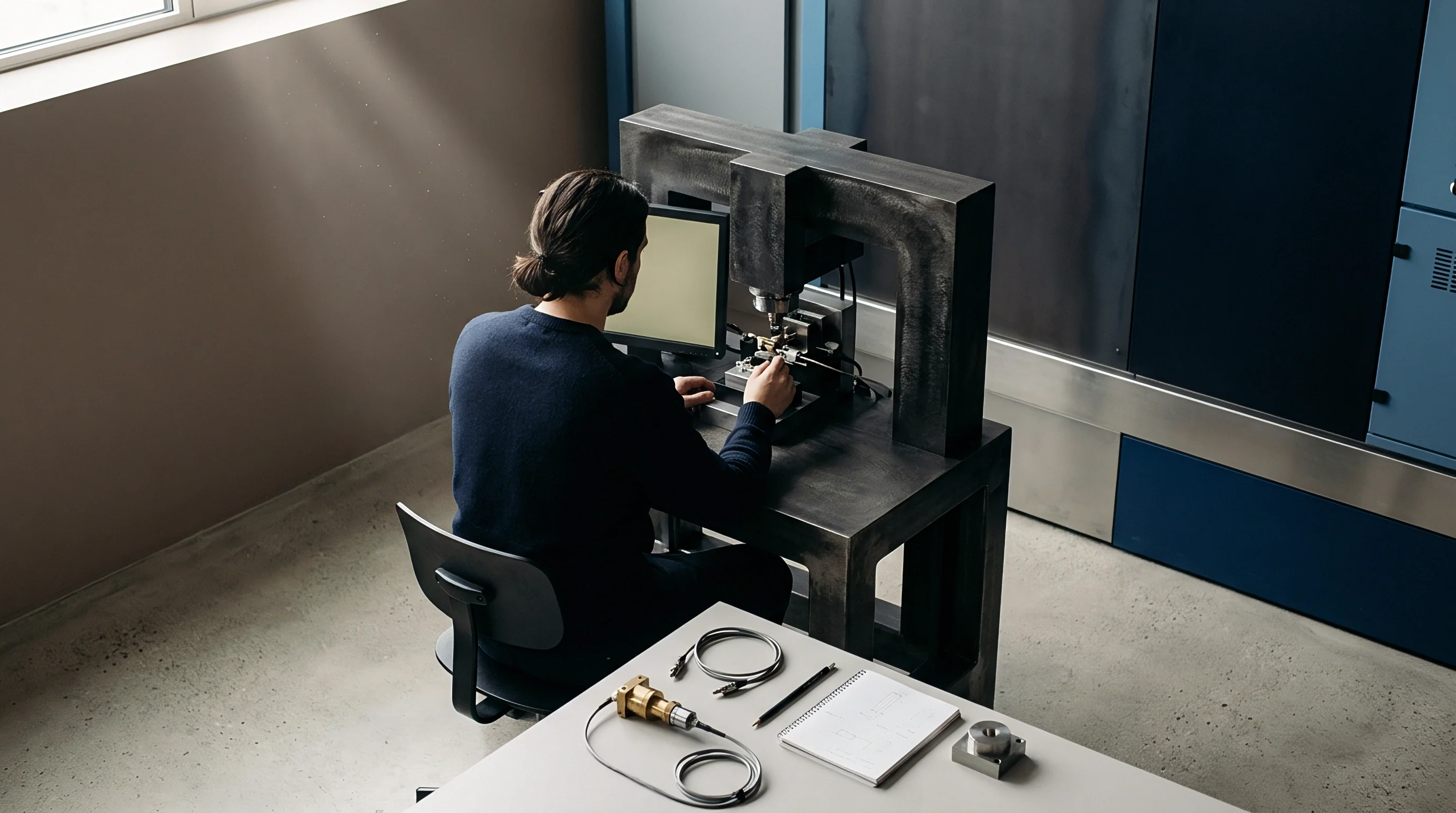
Field Verification Sequence for Transfer Standards
Executing a structured verification protocol ensures that portable temperature references hold accreditation boundaries. Field transfer standards must undergo periodic cross-verification against primary laboratory standards under controlled, static equilibrium conditions to detect baseline drift.
In-field verification protocols establish thermal stability criteria before logging calibration data points. Automated calibrators monitor insert block stability by tracking internal temperature derivative values over time. Defining stability as a maximum drift rate of 0.05 K per five-minute period prevents logging data during transient ramp tails.
- Ramp Speed Verification verifies that calibrator heating and cooling velocities remain within certified linear control limits during automated sweeps.
- Immersion Depth Compliance confirms that reference probes and target sensors reach equal immersion depths within the active uniform zone.
- Dual Reference Cross-Checks deploy two independent reference PRTs inside the calibrator block to continuously isolate spatial block gradients from sensor drift.
- Dwell Time Validation ensures that automated calibration scripts maintain sufficient thermal soak periods to eliminate residual transient time lag.

Auditing Certificate Validity against Thermal Ramp Data
Laboratory certificates reflecting steady state immersion conditions fail to protect against field ramp errors. When auditing third-party calibration service providers, quality engineers must examine whether declared accuracy claims were collected under static or dynamic conditions.
Tolerance margins shrink in field conditions. If a calibration vendor utilizes automated fast-ramp calibration systems to increase certificate volume, the reported expanded uncertainty must explicitly include dynamic tracking and spatial gradient terms. Verification certificates lacking explicit dynamic uncertainty terms are limited to static operating regimes.
Whether field technicians can realistically measure transient spatial profiles during routine plant maintenance without specialized multi-channel logging hardware remains an open technical challenge.


Penalty
Unrecorded measurement errors during field calibration introduce financial risks across production lines. In regulated industries such as pharmaceutical manufacturing, chemical processing, and semiconductor fabrication, out-of-spec temperature measurements compromise product quality and batch yield. Calibration costs climb with dwell length.
False acceptance occurs when a drifting, out-of-tolerance sensor passes verification due to uncounted dynamic errors masking its true offset. If a positive calibration ramp lag cancels out a negative sensor drift, the sensor appears accurate during test execution. Once placed back into static process operation, the dynamic lag offset disappears, leaving the uncorrected sensor drift to ruin production batches.
False rejection occurs when thermal gradients cause a fully functional, highly accurate sensor to fail field calibration. Scrapping or prematurely recalibrating compliant instrumentation incurs unnecessary hardware replacement costs and technician labor hours. Scrapping good sensors inflates maintenance budgets needlessly.

Financial Exposure of Uncalibrated Dynamic Errors
False acceptance of out-of-tolerance process instrumentation causes severe yield loss in regulated manufacturing. A critical bioreactor operating at a temperature offset of 0.5 K due to an uncounted field calibration error can ruin a production batch worth hundreds of thousands of dollars.
Regulatory audit findings present further commercial penalties. Regulatory agencies issuing non-compliance notices against inadequate instrumentation verification records require costly root-cause investigations, process validation audits, and potential product recalls. Setting dynamic uncertainty budgets protects plant operators against product liability exposure.
| Calibration Strategy | Dwell Time Per Point (min) | Total 5-Point Test Duration (min) | Expanded Uncertainty (mK) | Technician Labor Cost ($) | Residual Risk Exposure Level |
|---|---|---|---|---|---|
| Fast Ramp (Dynamic, No Dwell) | 0.0 | 15.0 | 304.0 | 25.00 | High (Uncontrolled False Pass Risk) |
| Short Dwell (Partial Equilibrium) | 2.0 | 25.0 | 112.0 | 41.67 | Moderate (Minor Transient Lag) |
| Standard Field Dwell | 5.0 | 40.0 | 42.0 | 66.67 | Low (Acceptable Operational Risk) |
| Full Laboratory Equilibrium | 15.0 | 90.0 | 24.0 | 150.00 | Negligible (Maximum Precision) |

Optimizing Dwell Periods for Field Efficiency
Balancing calibration cycle times against measurement uncertainty yields measurable operational savings. Extending dwell times at each calibration temperature setpoint reduces transient spatial gradients and allows thermal time lags to decay, reducing combined uncertainty.
Ramp speed dictates field yield. Technicians running abbreviated five-minute dwell routines increase throughput, completing more sensor checks per shift. The resulting dynamic uncertainty expansion requires widening process operational tolerances.
Establishing optimal dwell periods using calculated dynamic uncertainty budgets allows quality managers to maximize technician field efficiency while maintaining absolute regulatory compliance.
Aligning technician labor costs with dynamic uncertainty models creates a quantifiable boundary where longer dwell times deliver clear financial returns through reduced process risk.