Dynamic Temperature Transient Induced Drift Corrections and Uncertainty Bounds in Sub Arcminute Leveling Platforms
Dynamic temperature transients induce spatial heat flux that invalidates static calibration, requiring derivative filtering to bound tilt drift below arcminutes.

Gradient
When an ambient ramp of 2 Kelvin per minute hits a closed-loop sub-arcminute tilt platform, systematic angular drift sets in long before internal thermal sensors register any bulk shift. Conduction delays through structural members, uneven expansion across flexure hinges, and localized dissipation inside differential capacitance pickoff stages all contribute. Inside a sealed aluminum housing, an ordinary industrial servo-inclinometer or quartz flexure accelerometer can develop internal temperature differentials exceeding 0.4 Kelvin between opposing sensing electrodes during modest operational transients.
That gradient produces differential mechanical strain, showing up on uncompensated platforms as a false gravitational tilt signal between 12 and 45 arcseconds.
Thermal equilibrium calibration curves fall apart during dynamic heating. Conventional static compensation maps sensor output in a uniform, slowly stepped chamber ~ typically 0.1 Kelvin per minute with two-hour dwell periods. In real operating environments like outdoor pedestals, naval stabilized weapon stations, or borehole alignment tooling, the hardware runs into asymmetric radiant boundaries, sudden motor driver heat, and shifting convective drafts.
The resulting internal gradients generate mechanical stress patterns that static polynomial lookup tables simply cannot track.
Resolving this transient bias requires tracing the direct thermal conduction paths across the baseplate and flexures. Heat diffuses through aviation-grade aluminum 6061-T6 at roughly 64 square millimeters per second. On a mounting base with a 50-millimeter baseline distance between kinematic interfaces, establishing a linear gradient across the structural load path takes several hundred seconds.
While that thermal front moves through, transient deformation warps the mounting plinth, introducing true physical tilt while simultaneously skewing the element’s capacitive gap. During the first twenty minutes of a thermal transient, platforms relying solely on static calibration show drift excursions three to eight times higher than their steady-state datasheet ratings indicate.
Thermal chamber calibration conducted at steps of 0.1 Kelvin per minute fails to prevent dynamic leveling drift reaching 45 arcseconds under operational gradients.
Procurement specifications for sub-arcminute systems often cite residual temperature coefficients under 0.2 arcseconds per Kelvin. That metric is valid only under strict isothermal conditions, where the enclosure, flexures, sensor die, and structural frame stay at identical temperatures. Subjecting incoming units to a controlled 1.5 Kelvin per minute convective air stream quickly demonstrates the boundary of that specification: uncompensated dynamic drift breaches the sub-arcminute threshold within four minutes of applying the heat source.

Expansion
Thermal deformation in leveling mechanisms traces directly to mismatched coefficients of thermal expansion across the assembly. Leveling platforms rely on kinematic mounts, fine-pitch leadscrews, piezoceramic actuators, or structural flexure hinges to hold planar orientation against gravity. Bolting aluminum frames to structural steel bearings and brass adjustment collars forms local bimetallic junctions.
As temperatures climb dynamically, steel fasteners restrain the faster-expanding aluminum base, setting up localized bending moments that tilt the measurement axis away from true vertical.
Take a differential tilt platform driven by two vertical actuator columns spaced 150 millimeters apart. If one column absorbs conductive heat from an adjacent motor controller while the opposite column radiates outward into open air, the columns expand unevenly. Aluminum has a linear coefficient of thermal expansion of 23.1 microstrain per Kelvin at 20 degrees Celsius.
A temperature difference of merely 0.15 Kelvin across that 150-millimeter baseline expands one actuator column 52 nanometers relative to the other. That 52-nanometer vertical run produces an uncommanded tilt of 0.071 arcseconds. While negligible in coarse machinery, platforms targeted below 5 arcseconds quickly run through their total error budget once operational heating pushes the gradient to 1.0 or 2.0 Kelvin.
Silicon and quartz sensing elements introduce packaging strain of their own. When a micromachined capacitive accelerometer die is mounted to an alumina ceramic substrate with epoxy, temperature swings generate severe shear stress along the bond line. The glass transition temperature of the die-attach elastomer, combined with its high volumetric expansion, exerts uneven forces on the anchored flexures of the silicon proof mass.
The mass shifts under mechanical packaging strain alone, producing an electrical response identical to physical gravitational tilt.
| Material Designation | Thermal Conductivity (W/m·K) | Expansion Coefficient (ppm/K) | Thermal Diffusivity (mm²/s) | Elastic Modulus (GPa) |
|---|---|---|---|---|
| Aluminum 6061-T6 | 167 | 23.1 | 64.3 | 68.9 |
| Stainless Steel 304 | 16.2 | 17.3 | 4.2 | 193.0 |
| Titanium Grade 5 (Ti-6Al-4V) | 6.7 | 8.6 | 2.9 | 113.8 |
| Invar 36 (FeNi36) | 10.15 | 1.2 | 2.8 | 141.0 |
| Fused Silica Quartz | 1.38 | 0.55 | 0.8 | 72.0 |
| Silicon (Single Crystal) | 149 | 2.6 | 88.0 | 130.0 to 188.0 |
Selecting structural materials requires balancing thermal diffusivity against absolute expansion. Stainless steel expands less than aluminum, but its low thermal conductivity yields a thermal diffusivity of only 4.2 square millimeters per second. Under asymmetric heat, stainless steel plinths trap steep, localized gradients for extended periods, whereas aluminum redistributes thermal energy quickly and recovers geometric balance much sooner.
Invar 36 minimizes linear expansion, but machining difficulty, raw material cost, and the risk of permanent stress-relief shifts during thermal cycling keep it confined to isolated metrology loops.
Mechanical joints are a frequent culprit in thermal hysteresis. Torqued bolted joints develop internal friction fields, and as mating components expand at different rates, microscopic slip takes place across the interfaces. Once the thermal transient subsides, the assembly rarely settles into its original angular position, leaving an uncorrected zero-point shift between 2 and 10 arcseconds.
Kinematic cup-cone-vee mounts using hardened tool steel spheres seated on tungsten carbide flats bypass this by permitting free thermal growth along defined vectors while maintaining rigid constraints on the tilt axes.
Leaving structural expansion unaddressed forces an impossible burden onto signal processing. Firmware filtering cannot separate physical foundation tilt from asymmetric chassis deformation. The structural frame must maintain thermal symmetry around the sensing core and block uneven drafts from reaching load-bearing pillars.
Without structural symmetry, dynamic correction models must handle far too many uncontrolled spatial variables, diluting their effectiveness.
Transduction
Precision leveling platforms generally rely on three transduction mechanisms to measure orientation relative to gravity: closed-loop quartz flexure servo accelerometers, micro-electro-mechanical capacitive silicon sensors, and electrolytic tilt sensors. Each reacts differently to thermal transients, depending on how mechanical displacement is converted into electrical impedance or current.
Quartz flexure servo accelerometers mount an amorphous quartz proof mass on an etched flexure hinge, suspended within a permanent magnetic field inside a voice coil. When tilt displaces the mass from null, the capacitive pickoff detects the change, and a servo amplifier drives current through the torquer coil to restore position; that feedback current constitutes the sensor output. As the unit heats up, the field strength of the permanent magnet ~ typically Alnico or samarium cobalt ~ drops predictably.
Samarium cobalt shifts at roughly minus 0.035 percent per Kelvin. More troublesome is the heat generated within the voice coil itself. Rapid slewing or high-vibration leveling cycles spike coil dissipation, creating an internal thermal plume inside the hermetic casing that distorts pickoff electrode spacing.
Electrolytic tilt sensors use a hermetically sealed glass or ceramic vial filled with conductive fluid and a precision gas bubble, into which platinum or tungsten excitation electrodes dip. Tilting changes the wetted surface area of the electrodes, altering bridge resistance across opposing legs. These sensors can resolve 0.01 arcseconds over narrow ranges, but their dynamic thermal behavior is notoriously non-linear.
Temperature swings change the viscosity and surface tension of the fluid, reshaping the bubble geometry. During a thermal ramp, volumetric expansion alters the sensor’s scale factor, while uneven heat transfer across the glass vial triggers internal fluid convection that can swing false tilt readings by several arcminutes until the cell returns to equilibrium.
Capacitive MEMS inclinometers rely on micromachined silicon comb fingers or differential parallel plates. Silicon’s high thermal conductivity prevents large internal gradients across the die, but the differential capacitive node works with minute signals, often on the order of tens of attofarads per arcsecond. The readout ASIC, co-packaged with or wire-bonded to the MEMS die, burns between 5 and 30 milliwatts.
This internal load establishes a persistent thermal offset between the ASIC substrate and the sensor frame. Any sudden change in external airflow disturbs that equilibrium, altering the operational bias voltage and creating an angular drift that tracks the cooling rate rather than real mechanical tilt.
The primary vulnerability of capacitive MEMS elements during thermal transients is package-stress transfer rather than temperature-dependent changes in silicon elasticity.
Choosing an architecture for demanding outdoor service involves balancing raw sensitivity against environmental behavior. Quartz flexure sensors deliver excellent long-term bias stability and survive severe shock, but high unit cost and coil dissipation introduce continuous thermal overhead. MEMS devices run cool and fit restricted spaces, but package-stress coupling necessitates intricate mathematical filtering.
Electrolytic vials yield unmatched sub-arcsecond repeatability on vibration-isolated platforms, but dynamic temperature swings leave them completely unusable until temperatures level out.
Drift
Dynamic tilt drift breaks down into two distinct mechanisms: spatial gradients across the sensor body and the ambient rate of temperature change over time. Classical calibration addresses static drift by mapping bias against a single temperature sensor under steady-state conditions. Under dynamic conditions, however, tilt error becomes a multi-variable problem driven by the time derivative of temperature, spatial differentials between structural points, and mechanical strain rates.
Dynamic modeling isolates these bias terms into separate operational components. Instantaneous bias reflects static thermal offset, the transient rate of change, and spatial gradients across the frame. Writing out these contributions reinforces why zero-rate chamber calibrations fail to capture the forces driving operational errors.
The combined dynamic bias error can be described functionally as:
Theta_drift(t) = P_static(T_die) + C_transient (dT_die / dt) + Sum(K_grad_i Delta_T_i(t)) + H_viscoelastic(t)
The term P_static represents the standard static polynomial calibration against die temperature T_die, typically a third-order or fifth-order fit. The second term tracks the rate of change directly, where C_transient is the dynamic transient coefficient in arcseconds per Kelvin per second. The third term sums spatial gradients, Delta_T_i, measured by resistance temperature detectors across the mount, scaled by structural sensitivity coefficients K_grad_i.
The final term, H_viscoelastic, accounts for mechanical relaxation in die-attach adhesives and structural potting, which lag the thermal input.
A worked example demonstrates the scale of these dynamic terms on an unshielded dual-axis quartz inclinometer. The unit sits on an aluminum bracket exposed to an ambient ramp from 15 degrees Celsius to 35 degrees Celsius at 1.2 Kelvin per minute (0.02 Kelvin per second). The static thermal polynomial carries a calibrated coefficient of 0.15 arcseconds per Kelvin, which under steady-state assumptions implies a maximum error of 3.0 arcseconds across the 20-Kelvin swing.
During the actual ramp, the operational error profile behaves quite differently:
- Static thermal bias yields an expected maximum excursion of 3.0 arcseconds across the full 20-Kelvin range when evaluated at infinite dwell times.
- Temporal derivative coefficient for this assembly, characterized through thermal shock testing, equals minus 142 arcseconds per Kelvin per second, generating an instantaneous dynamic offset of minus 2.84 arcseconds purely due to the 0.02 Kelvin per second heating rate.
- Spatial gradient development between the baseplate thermal sensor and the internal pickoff electronics reaches 0.35 Kelvin during the middle of the ramp; the structural gradient coefficient is 48.0 arcseconds per Kelvin, contributing an additional unmodeled error of 16.80 arcseconds.
- Combined dynamic tilt error peaks at 22.64 arcseconds during the active heating phase, exceeding the static datasheet prediction by more than seven times before dropping back toward the static curve as the temperature stabilizes.
This breakdown shows why sub-arcminute platforms fail field accuracy checks when relying entirely on static tables. The dynamic error correlates with conductive heat flux rather than absolute temperature. When heat flux peaks, the spatial gradient Delta_T reaches its maximum, pushing structural and capacitive asymmetry to extreme values.
Compensating for dynamic error requires measuring both the temporal temperature derivative and local spatial differentials in real time. Differentiating raw temperature signals directly introduces quantization noise that destabilizes closed-loop control. Clean derivative terms require 24-bit delta-sigma acquisition alongside finite impulse response filtering or a state-space Kalman filter, avoiding phase delays that would displace the correction vector from the mechanical strain peak.
Thermal hysteresis complicates the profile once the heating phase ends. As the assembly cools, the temperature derivative changes sign, but joint friction and adhesive layers relax along a path different from the ramp-up curve. This non-reversible mechanical behavior leaves residual angular errors that persist long after the external temperature stabilizes, requiring the firmware to track thermal trajectory and cycle direction to constrain zero-point uncertainty.
Mitigation
Preventing dynamic thermal drift in precision platforms requires combining structural isolation, active thermal control, and algorithmic state estimation. Relying on any single layer leaves the platform exposed to unmodeled environmental changes.
Physical barriers provide the first defense against steep heat flux. Enclosing the sensing core in an isotropic conductive shell wrapped with outer multilayer insulation shields the package from convective swings. A polished gold-anodized aluminum outer skin reflects radiant spikes, while an internal high-diffusivity copper liner routes incoming heat around the perimeter, turning directed flux into a uniform, symmetrical rise.
Stand-offs separating the sensing unit from the structural plinth should use low-conductivity technical ceramics like zirconium dioxide or Macor machinable glass-ceramic instead of metal hardware.
Multi-point thermal mapping across internal structural nodes provides the physical basis for real-time spatial gradient extraction.
Active thermal regulation holds the core at an elevated setpoint above the highest expected ambient condition. A platform specified to 50 degrees Celsius can maintain its internal core at 55 degrees Celsius using polyimide heating elements managed by a pulse-width modulated PID loop. Keeping the internal core within plus or minus 0.05 Kelvin suppresses dynamic spatial gradients.
However, continuous heating draws 2 to 12 watts and accelerates the aging of internal silicon components and electrolytic seals.
Where power, weight, or enclosure size rule out active heating, algorithmic compensation offers an effective alternative. Instead of relying on a single die sensor, the assembly incorporates miniature platinum resistance thermometers (PT1000) or high-precision digital temperature sensors at critical structural nodes. The firmware then runs a dynamic multi-input single-output FIR filter or a state-space Kalman filter that uses the temperature differentials between these locations alongside the rate of change of the sensor body.
A structured implementation sequence organizes the design and verification workflow:
- Mechanical axis decoupling seats the primary sensing core on kinematic mounts to prevent structural plinth warping from transferring mounting torques directly into the inclinometer housing.
- Thermal boundary mapping places at least four resistance thermometers across the assembly: one on the primary sensing element, one on the readout circuit board, and two on opposing structural plinth legs.
- Chamber impulse testing subjects the instrumented platform to thermal step functions and ramps up to 3 Kelvin per minute to extract empirical transfer functions linking spatial thermal gradients to output bias shifts.
- Derivative matrix integration deploys real-time digital filtering to compute the local time derivative of temperature, routing the derivative terms into a multi-variable correction matrix executed inside the platform microcontroller.
- Hysteresis envelope bounding runs closed-loop heating and cooling cycles across the full operating range to quantify the residual non-recoverable angular drift and set realistic measurement uncertainty limits.
Algorithmic models derived in the lab often fall short in the field if internal electronic dissipation was ignored during bench testing. Changing processor loads or motor duty cycles introduce internal heat sources absent during passive oven runs. The compensation routine must ingest operating state telemetry from nearby motors and processing cores to separate internal power fluctuations from ambient weather patterns.
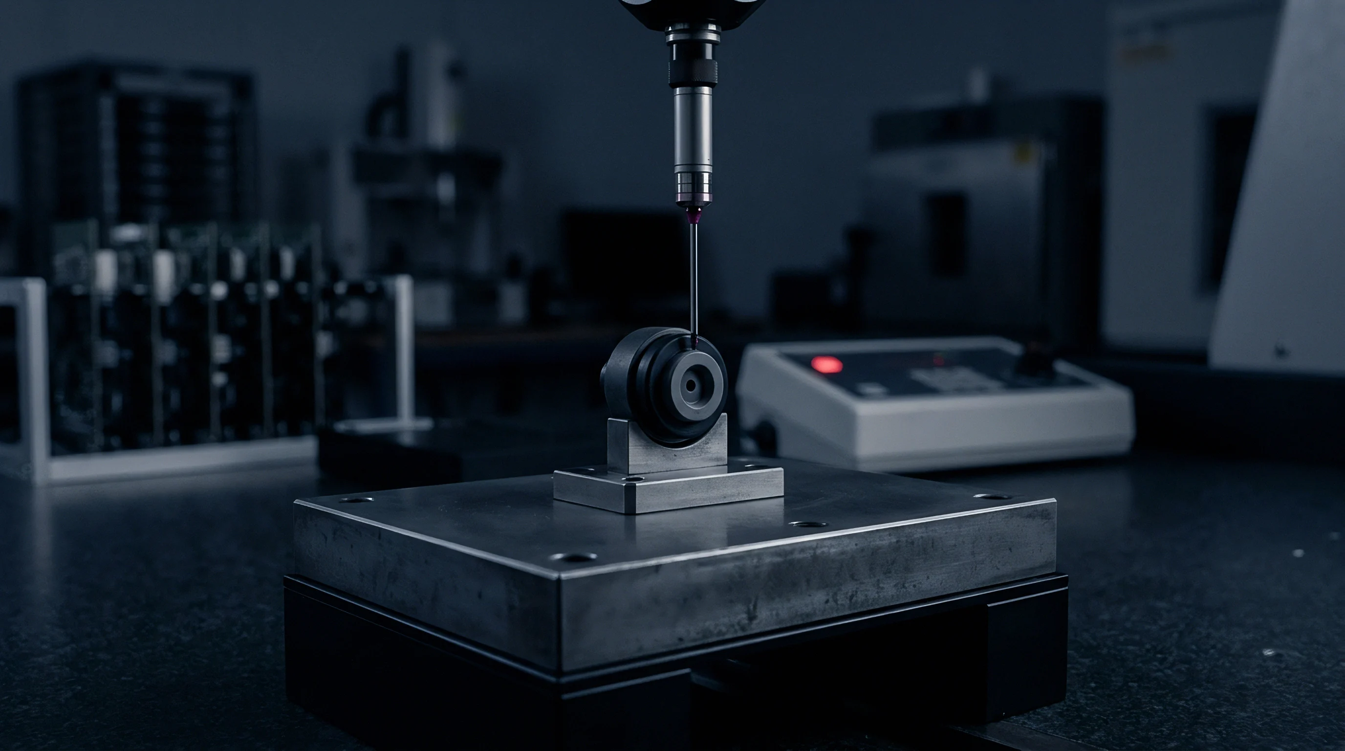
Uncertainty
Proving sub-arcminute capability requires converting residual dynamic drift into an uncertainty budget structured under the Guide to the Expression of Uncertainty in Measurement (JCGM 100:2008). Datasheets often present static repeatability as total uncertainty, ignoring the scatter caused by dynamic operating conditions. A defensible budget treats dynamic thermal effects as Type B systematic uncertainties with assigned probability distributions, combined with baseline sensor noise via root-sum-square calculation.
Overall leveling uncertainty encompasses base mechanical noise, digitizer resolution, static polynomial residuals, and unmodeled dynamic thermal gradients. Allan deviation plots establish the baseline velocity random walk and bias instability under isothermal conditions. On a high-grade MEMS inclinometer, angle random walk typically sits near 0.005 arcminutes per root hour, with bias instability leveling off near 0.02 arcseconds.
In field applications, however, dynamic thermal effects completely overshadow these baseline noise figures.
| Source of Uncertainty | Value (± arcsec) | Probability Distribution | Divisor | Standard Uncertainty u_i (arcsec) |
|---|---|---|---|---|
| Sensor Noise Floor (10 Hz Bandwidth) | 0.80 | Normal | 1.000 | 0.80 |
| Analog-to-Digital Quantization (24-bit) | 0.05 | Rectangular | 1.732 | 0.03 |
| Static Thermal Polynomial Residual | 1.20 | Normal | 2.000 | 0.60 |
| Dynamic dT/dt Transient Residual | 3.50 | Rectangular | 1.732 | 2.02 |
| Spatial Gradient ΔT Residual | 4.20 | Rectangular | 1.732 | 2.42 |
| Mounting Joint Thermal Slip Hysteresis | 2.00 | Rectangular | 1.732 | 1.15 |
| Combined standard uncertainty u_c equals 3.49 arcseconds; expanded uncertainty U (k=2, 95% confidence) equals 6.98 arcseconds. | ||||
The table shows that unmodeled dynamic thermal effects account for more than 80 percent of the total variance during a 1.5 Kelvin per minute ramp. Even with active mathematical compensation, residual errors remain because of second-order thermal lag and micro-convection inside the housing. If dynamic derivative and spatial gradient terms are left out of the compensation loop, those residual terms expand to 15.0 and 22.0 arcseconds, pushing expanded uncertainty U well past the 60 arcsecond sub-arcminute ceiling during rapid temperature shifts.
Expanded uncertainty relies on a coverage factor k, generally set to k=2 for an approximate 95 percent confidence interval. When dynamic transients create skewed, non-Gaussian error distributions, calculating effective degrees of freedom using the Welch-Satterthwaite equation becomes essential. If dynamic errors are governed by rectangular distributions with few degrees of freedom, assuming a normal Gaussian distribution will underestimate the true risk of angular excursion.
The operational uncertainty budget expands and contracts continuously. When the rate of ambient temperature change increases from 0.5 Kelvin per minute to 3.0 Kelvin per minute, dynamic residual terms scale almost linearly, widening the uncertainty band. An assembly running comfortably inside a 10-arcsecond window overnight can breach its specification at sunrise as radiant solar load sets up steep, directional heat flux through the housing.
Qualification
Incoming inspection for sub-arcminute platforms must replicate dynamic heat flux rather than relying on standard isothermal soak steps. Standard qualification testing under MIL-STD-810 or IEC 60068-2-14 specifies thermal shock or slow cycles with long dwell periods, intended to check structural survival rather than in-situ metrology. Passing an isothermal check at minus 20 degrees Celsius and plus 60 degrees Celsius gives no indication of whether the instrument will maintain sub-arcminute accuracy while transitioning between those temperatures.
Do Chamber Air Currents Invalidate Platform Calibration?
Test chamber circulation fans move air at 1.5 to 5.0 meters per second to keep chamber temperature uniform. Blown directly against a sensor chassis, this forced convection creates turbulent boundary layers and artificial internal gradients. Evaluating an unshielded unit under direct chamber airflow characterizes the oven’s internal aerodynamics rather than the instrument’s intrinsic thermal drift.
Reliable testing requires placing the assembly inside a sealed, heavy-walled aluminum damping chamber within the oven, blocking forced drafts while allowing conductive and radiant transfer to proceed predictably.
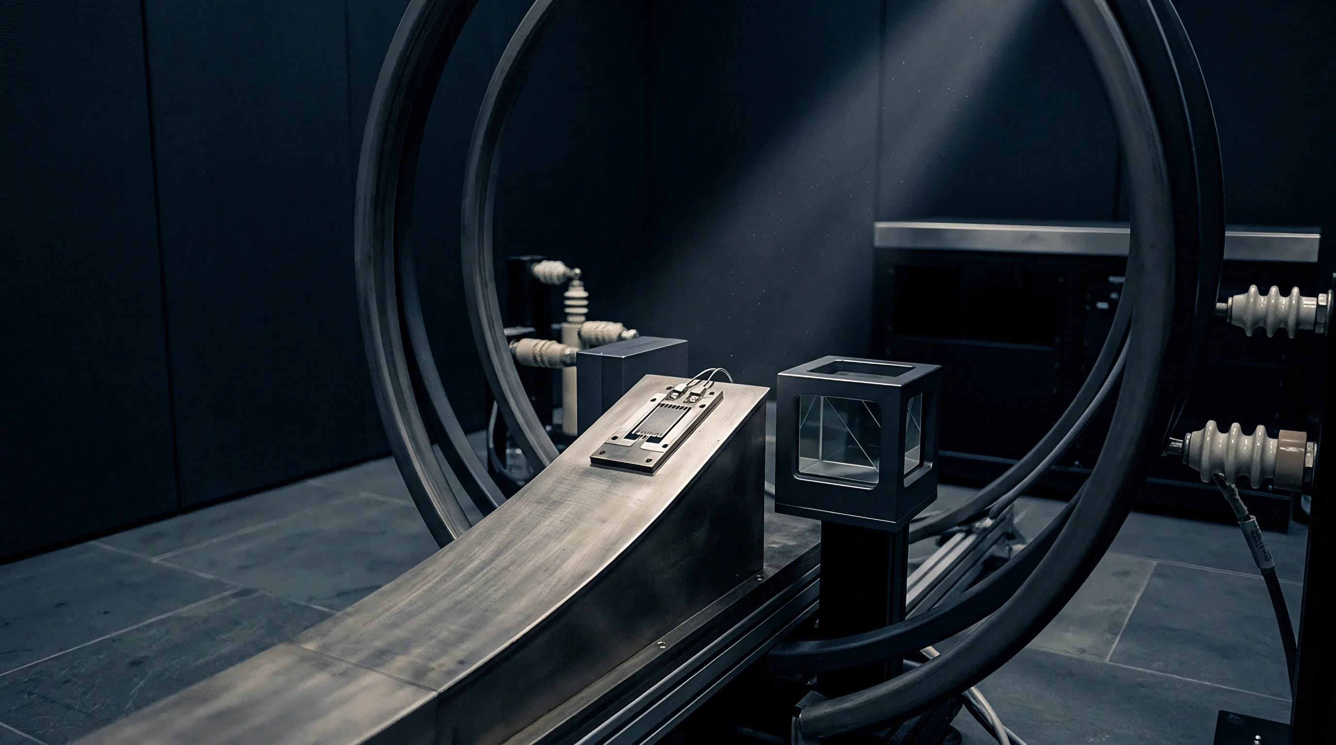
A reliable test bench uses an external optical indexing table or dual-axis tilt station, reading platform orientation through an optical flat port with a precision dual-axis autocollimator. The autocollimator provides an independent reference traceable to national standards, with uncertainty below 0.05 arcseconds over a plus or minus 100 arcsecond range. The test runs a continuous ramp of 2.0 Kelvin per minute across the entire operating range, continuously logging the optical reference angle against the sensor’s reported electrical output.
Relying on temporal rate effects to average out over operational deployment cycles fails in closed-loop systems, where transient drift triggers physical actuator motion that introduces permanent positioning errors. Sourcing specifications must explicitly define dynamic thermal compliance: the sensor must maintain its stated angular accuracy envelope across all ambient thermal slopes up to a specified maximum rate of change, verified under continuous ramp conditions.
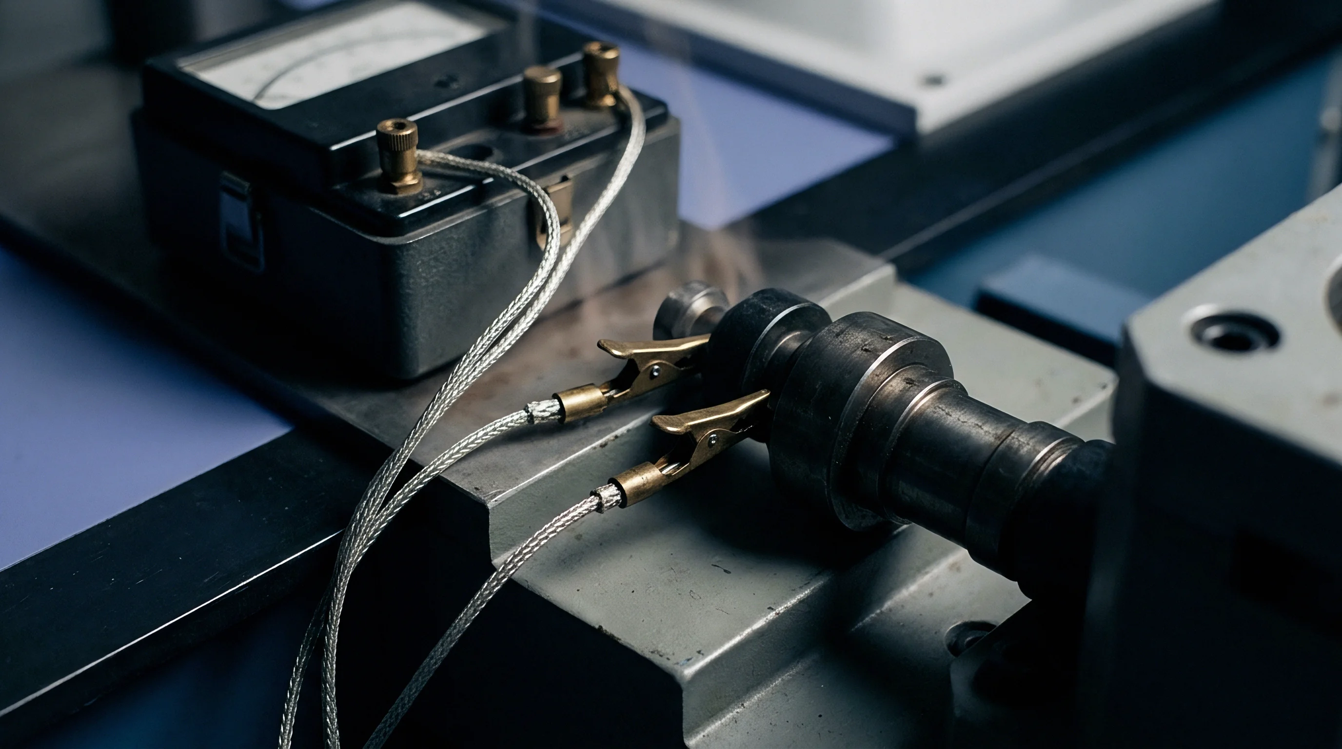
Factory acceptance packages must supply raw, unbuffered time-series records of mechanical tilt output alongside every integrated temperature channel during continuous thermal ramps. Accepting factory calibration files containing only static polynomial coefficients leaves the full commercial risk of operational drift with the buyer. If a manufacturer lacks the metrology setup to record real-time autocollimator angles during thermal transitions, the cost of internal qualification and dynamic compensation modeling must be factored into the landed component cost.