Isolated Silicon Pressure Cell Oil Dosing Volume Tolerances and Temperature Hysteresis
Isolated silicon cell thermal hysteresis depends directly on micro-dosing oil volume accuracy and outer diaphragm compliance balance.


Cavity
An isolated piezoresistive pressure cell uses a hermetically sealed fluid chamber to transfer process media pressure from a thin isolation diaphragm to a silicon micro-electro-mechanical sensor die. The internal oil volume sits trapped between the flexible outer metal membrane, the rigid header substrate, and the glass-passivated silicon chip. Because silicon strain gauge elements cannot survive direct exposure to corrosive process liquids or conductive gases, the internal fluid fill serves as the sole mechanical coupling mechanism.
This fluid layer introduces hydraulic compliance, thermal expansion forces, and mechanical stress paths that directly govern sensor output stability across changing ambient environments.
Total fill fluid volume ranges from 5 microliters in ultra-compact 12-millimeter sensor headers to over 80 microliters in heavy-duty industrial designs. The isolation diaphragm ~ typically 316L stainless steel, Hastelloy C-276, Monel, or Tantalum between 20 and 50 micrometers thick ~ has a characteristic bending stiffness. When external pressure changes, the diaphragm deflects, displacing a minute volume of fill oil and transmitting hydraulic pressure to the piezoresistive silicon diaphragm.
The silicon die itself undergoes minimal deflection under load, operating at a displacement stiffness orders of magnitude higher than the outer metallic foil.

Isolation Diaphragm Structural Mechanics
The stiffness ratio between the isolation diaphragm and the internal fill fluid sets baseline pressure transfer fidelity. The outer metallic diaphragm behaves as a non-linear spring. At zero differential pressure, the metal foil rests in a neutral, stress-relieved state.
Any volume shift in the internal oil cavity pushes the isolation diaphragm outward or inward from its zero-bias plane, establishing a pre-stress state in the metal skin before external process pressure arrives.
A corrugated metallic diaphragm’s spring rate depends on outer diameter, crest depth, wave count, and material yield strength. Corrugations reduce radial stiffness, allowing higher volumetric displacement per unit of applied pressure than a flat disc would permit. A flat diaphragm of equivalent diameter creates excessive hydraulic resistance, causing severe thermal zero shifts as internal fluid expands.
Corrugated profiles allow controlled out-of-plane deflection, accommodating fluid volume changes while keeping pressure transfer linear across working temperature ranges.
Internal cavity geometry must minimize dead volume while maintaining structural clearance around wire bonds, glassfeedthrough posts, and sensor die edges. Oil channels extending from the rear dosing port to the front sensor face add parasitic fluid volume, which expands with temperature to drive unwanted diaphragm deflection. Precision machining matches the header cavity to the rear profile of the isolation diaphragm, leaving a uniform oil gap between 50 and 150 micrometers when the diaphragm sits at rest.

Fluid Cavity Volume and Compliance Metrics
Hydraulic compliance within the sealed capsule combines three components: structural compliance of the isolation diaphragm, bulk modulus of the fill fluid, and mechanical compliance of trapped gas micro-bubbles. Total system compliance dictates how internal fluid pressure responds to ambient temperature changes. Internal differential pressure generated by thermal expansion equals fluid expansion volume divided by total capsule structural compliance.
Standard silicone fill oils have a bulk modulus between 1.0 and 1.5 gigapascals at room temperature. Because of this finite compressibility, the fluid acts as a stiff hydraulic spring. If the metal isolation diaphragm were infinitely stiff, thermal oil expansion would generate massive internal pressure, crushing the MEMS sensor die or blowing out the diaphragm seal.
Conversely, an extremely compliant diaphragm absorbs expansion without building pressure, but leaves the sensor vulnerable to orientation errors from fluid head shifts.
Standard silicone fill fluids exhibit volumetric thermal expansion coefficients near 0.00095 per degree Celsius, expanding nearly one percent in total volume over a 100 degree temperature rise.
As oil volume expands under heat, the isolation diaphragm moves outward to accommodate the additional fluid. This deflection alters tension across the corrugation waves, exerting force on the fluid column that transfers back to the silicon sensor element. This parasitic force shows up as an uncommanded pressure signal ~ recognized on the calibration bench as thermal zero shift.
The shift scales directly with initial fill volume and expansion rate, and inversely with outer diaphragm compliance.
Manufacturing tolerances in header machining, silicon die mounting depth, and diaphragm stamping create cell-to-cell variations in baseline cavity volume. A 10-micrometer variance in cavity depth on a 15-millimeter sensor header changes internal volume by approximately 1.76 microliters. This dimensional scatter alters the baseline volume calculation and shifts thermal zero drift characteristics before oil dosing even starts.
As a result, header cavity depth tolerances require tight optical metrology controls during sub-assembly inspection.
The interplay between initial fill volume and diaphragm pre-stress sets the baseline thermal hysteresis response well before environmental testing begins.


Dosing
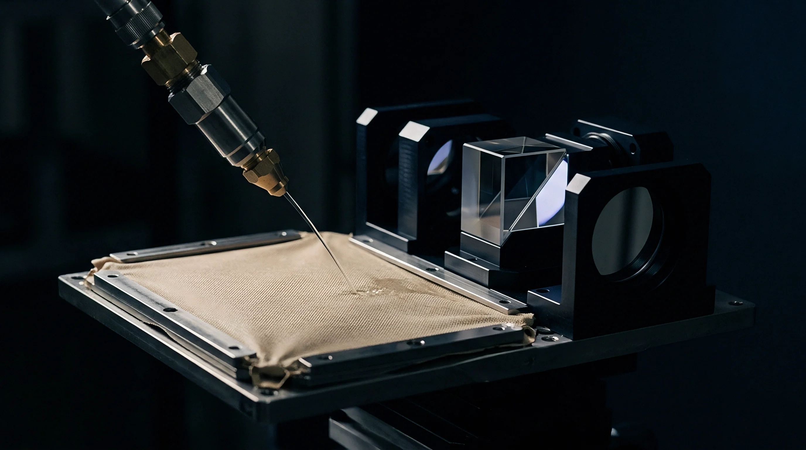
Fluid micro-dosing systems fill isolated pressure cell cavities through narrow capillary tubes using positive-displacement automated syringes or vacuum fill chambers. Repeatable dosing down to sub-microliter tolerances requires precise control over fluid viscosity, temperature, dispense pressure, and needle positioning. A deviation of just 0.1 microliter in a low-range capsule can shift the thermal zero point beyond acceptable calibration limits.
Vacuum dosing protocols evacuate the internal cavity below 0.05 millibar before injecting de-aerated fill fluid. Any air left inside creates micro-voids. Because air’s bulk modulus is four orders of magnitude lower than silicone oil’s, trapped gas bubbles are highly compressible.
During pressure cycles, trapped gas compresses and dissolves into the oil matrix, shifting zero offset. When temperature rises, the gas expands exponentially, driving non-linear zero shifts and leaving permanent offset after cool-down.

Capillary Micro Dosing Precision Limits
Positive-displacement micro-pumps with ceramic pistons achieve fill volume repeatability down to ±0.02 microliters under laboratory conditions. Production lines contend with continuous variables: fluid temperature drift, oil clinging to capillary tips, micro-bubble formation in supply lines, and cell port misalignments. Small temperature shifts at the dosing station change oil viscosity and density, altering dispensed mass when volumetric pumps operate on fixed stroke lengths.
Capillary tip design determines clean fluid detachment during dosing. Surface tension causes oil to form a meniscus on the needle tip; if a droplet clings during withdrawal, the cavity is left under-dosed. Micro-dosing nozzles use hydrophobic coatings and active vacuum cut-off pulses to shear droplets cleanly into the fill port.
Automated optical cameras verify droplet separation before the fill tube is sealed by laser spot welding or mechanical ball sealing.
Target dosing volumes balance low-temperature vacuum performance against high-temperature expansion limits. Under-dosing pulls the isolation diaphragm flat against the internal header floor at low operating temperatures. Once the metal membrane contacts the header wall, hydraulic coupling breaks, causing output flat-lining and severe loss of sensitivity.
Over-dosing pushes the diaphragm outward at room temperature, pre-stressing the metal in high tension and consuming stroke length before process pressure is ever applied.

Dissolved Gas Desorption under Thermal Cycling
Fill fluids absorb ambient gases during storage and handling through exposure to room air. Silicone oil dissolves up to 15 percent atmospheric air by volume at room temperature and pressure. To strip dissolved oxygen, nitrogen, and water vapor before dispensing, high-vacuum degassing protocols heat the oil to 80 degrees Celsius under agitation at absolute pressures below 0.01 millibar for several hours.
Any gas remaining dissolved in the oil desorbs during thermal cycling as temperature rises and local pressure drops. Bubbles nucleate at surface roughness features inside the machined header cavity or along the edges of the silicon die mount. These free gas bubbles alter total internal compliance during thermal exposure.
Upon cooling, re-absorption into the liquid phase proceeds slowly, leaving residual gas pockets inside the cavity for extended periods.
This dynamic gas solubility mechanism produces pronounced thermal hysteresis loops during temperature calibration. Sensor output follows a different trajectory while heating than it does while cooling. Preventing gas-phase nucleation requires keeping total dissolved gas below 50 parts per million mass fraction in the supply reservoir.
Oil dosing precision directly governs sensor thermal zero stability, long-term offset drift, low-temperature response linearity, and high-temperature mechanical limits.
| Fluid Chemistry | Kinematic Viscosity at 25°C (cSt) | Volumetric Expansion Coefficient (1/°C) | Max Dissolved Air Capacity (Vol %) | Nominal Dosing Tolerance (µL) | Operating Range (°C) |
|---|---|---|---|---|---|
| Polydimethylsiloxane (10 cSt) | 10.0 | 0.00096 | 15.2 | ±0.05 | -40 to +150 |
| Polydimethylsiloxane (5 cSt) | 5.0 | 0.00105 | 16.0 | ±0.03 | -55 to +125 |
| Fluorosilicone Oil | 100.0 | 0.00085 | 11.5 | ±0.08 | -40 to +200 |
| Synthetic Hydrocarbon Oil | 15.0 | 0.00078 | 8.5 | ±0.06 | -30 to +120 |
| Chlorotrifluoroethylene (CTFE) | 27.0 | 0.00075 | 7.0 | ±0.10 | -20 to +175 |
Fluid chemistry dictates baseline dosing accuracy limits and system response across operating extremes. Low-viscosity fluids quickly fill tight internal passages during vacuum dosing, but pose higher leakage risks across fill tube crimps prior to laser sealing. High-viscosity fluids minimize micro-leakage during assembly, but demand longer evacuation times and heated dispense lines to ensure complete, bubble-free filling.
Automated dosing lines use mass-based gravimetric verification downstream of dispense stations to confirm volumetric accuracy. Precision micro-balances weigh filled capsules against empty header baselines, flagging outliers before final hermetic sealing. Stations operating without inline gravimetric checks risk passing improperly filled units into downstream laser welding, compounding scrap rates during final calibration inspection.
Oil fill volume accuracy establishes the fundamental limit for uncompensated sensor zero drift across temperature.
- Diaphragm Bottoming Failure occurs when under-dosing pulls the outer metal membrane onto the header surface at cold temperatures, flattening sensor sensitivity entirely.
- High-Temperature Over-Straining occurs when over-dosing forces the outer membrane into non-linear plastic deformation during high-temperature exposure.
- Micro-Bubble Nucleation Hysteresis develops when high dissolved gas content forms free gas pockets under low pressure or elevated temperatures.
- Fill Port Seal Degas Leakage occurs when residual oil in the seal zone contaminates laser spot welds, producing micro-porosity and slow oil loss over time.
Volumetric dosing accuracy establishes the upper boundary for uncompensated baseline performance.


Swell
Volumetric expansion of trapped fill fluid under thermal loading creates structural strain throughout the cell assembly. The thermal expansion coefficient of silicone oil exceeds that of the surrounding stainless steel header by nearly sixty times. As ambient temperature rises, expanding fluid presses against the rigid boundaries of the cavity, seeking the path of least mechanical resistance.
The thin isolation diaphragm provides the primary mechanical relief path. Expanding fluid pushes the membrane outward, forcing it to bend along its corrugated profile. This displacement increases radial tensile strain across the metal surface, feeding mechanical stress back through the continuous oil column to the MEMS die and shifting the zero-pressure resistance of the piezoresistors.

Volumetric Fluid Expansion Mechanics
Thermal fluid swell follows a predictable volumetric relationship based on initial volume, thermal expansion coefficient, and temperature differential. The volume change equals initial oil volume multiplied by the expansion coefficient and temperature span. For example, a 30 microliter cavity of silicone oil with an expansion coefficient of 0.00096 per degree Celsius expands by 2.88 microliters over a 100 degree Celsius rise.
This 2.88 microliter expansion must be absorbed entirely by isolation diaphragm displacement. For a 15-millimeter diaphragm, accommodating this fluid volume requires outward centerline deflection of roughly 25 to 35 micrometers, depending on corrugation depth and geometry. The displacement forces the metal out of its neutral assembly state, inducing internal bending and shear stresses across the membrane.
Metal isolation diaphragms display elastic-plastic behavior. Under cyclic deflection driven by thermal oil expansion, the metal exhibits stress relaxation and elastic hysteresis. Upon cooling back to room temperature, the diaphragm does not instantly return to its initial resting geometry, retaining residual stress.
This residual stress alters hydraulic pressure on the oil column, appearing on test instruments as thermal zero hysteresis.

Diaphragm Deformational Hysteresis Curves
Thermal hysteresis curves plot output error across ascending and descending temperature cycles. In isolated silicon cells, zero hysteresis originates primarily from mechanical strain memory in the diaphragm and fluid-structure relaxation kinetics. The direction of the hysteresis loop depends on whether expanding fluid forces the membrane into higher tension during heating or allows it to relax during cooling.
Diaphragm material selection dictates thermal hysteresis magnitude. Austenitic 316L stainless steel work-hardens and shows moderate mechanical hysteresis under cyclic strain. Nickel alloys like Hastelloy C-276 offer superior corrosion resistance but have higher yield strength and spring-back resistance, altering the return curve profile.
Tantalum diaphragms provide extreme chemical resistance, but their low yield strength makes them susceptible to calibration shifts if over-driven by excessive oil fill volumes.
Excessive oil dosing volumes exacerbate isolation diaphragm stress hysteresis, doubling residual zero error across standard industrial operating temperature ranges.
When dosing tolerances drift positive, baseline fill volume increases. A positive dosing error of 0.5 microliters adds directly to the expansion volume, forcing the outer diaphragm deeper into its non-linear strain region at high temperatures. Because the corrugated membrane has a non-linear stiffness curve, internal hydraulic pressure ramps rapidly once deflection exceeds initial elastic limits, widening the hysteresis loop and driving up thermal zero shift.
Conversely, negative dosing errors reduce baseline volume, pulling the membrane inward toward the header floor. At operating temperatures down to -40 degrees Celsius, oil contraction further shrinks volume. If the initial fill was too low, contraction pulls the diaphragm flat against the header face.
Once physical contact occurs, hydraulic coupling breaks completely, creating sharp zero offset steps and irreversible calibration shifts upon return to room temperature.
Ignoring volumetric fluid expansion mechanics during cell design yields pressure sensors that permanently drift out of calibration class limits after their first thermal field cycle.


Bench
Evaluating isolated silicon pressure cell performance requires dedicated metrology setups that can separate pressure hysteresis from temperature-induced fluid hysteresis. Calibration benches combine automated pressure controllers, precision oil bath or air thermal chambers, ultra-stable DC power supplies, and high-resolution digital multimeters calibrated under ISO/IEC 17025 standards. Testing without strict thermal stabilization causes internal thermal gradients across the sensor body, skewing hysteresis measurements.
Thermal gradients across the header produce localized expansion differentials. If the outer diaphragm heats faster than the internal silicon die during thermal ramps, transient fluid pressure shifts mask true mechanical hysteresis. Thermal soak times must allow the entire assembly to reach equilibrium before reading output signals; standard protocols mandate minimum soak times of 30 to 45 minutes at each calibration point.

Thermal Hysteresis and Bilateral Temperature Runs
Unidirectional temperature testing misses thermal hysteresis entirely. Taking a zero offset reading at 25 degrees Celsius, ramping to 85 degrees Celsius, taking a second reading, and stopping leaves half the hysteresis loop unmeasured. Complete characterization requires a full bilateral cycle: starting at room temperature reference, ramping down to minimum operating temperature, returning to room temperature, ramping up to maximum operating temperature, and returning once more to room temperature baseline.
The difference between room-temperature baseline readings taken before and after thermal cycling defines total thermal zero hysteresis. This residual offset shows whether the internal oil volume and diaphragm assembly underwent reversible elastic deformation or suffered permanent strain. Units with high residual offset typically contain incorrect fill volumes, trapped gas micro-voids, or internal assembly stresses.
Characterizing pressure hysteresis requires holding temperature constant while cycling pressure from zero to full scale output and back. Isolating pressure hysteresis from thermal effects demands chamber stability within ±0.05 degrees Celsius throughout the sweep sequence. Automated deadweight testers or quartz resonant standards provide reference pressure inputs with expanded uncertainties below 0.01 percent of reading.

Separation of Zero Shift from Oil Strain Effects
Thermal zero shift (TZS) and thermal span shift (TSS) stem from different mechanisms inside the capsule. Zero shift arises as expanding fluid acts against diaphragm compliance alongside the silicon chip’s temperature coefficient of offset (TCO). Span shift originates primarily from the temperature coefficient of the gauge factor (TCGF), which reduces piezoresistive sensitivity as temperature rises.
Separating fluid-induced zero shift from intrinsic silicon behavior requires baseline testing on un-filled bare MEMS die assemblies alongside completed oil-filled capsules. Un-filled dies display purely silicon-level piezoresistive shifts. Subtracting the bare-die response from the oil-filled capsule response isolates the mechanical strain contribution caused by oil expansion and diaphragm stiffness interaction.
| Test Parameter | Control Tolerance | Measurement Device / Standard | Target Metrological Uncertainty |
|---|---|---|---|
| Chamber Temperature Stability | ±0.05 °C | Pt100 PRT / Precision Thermometer | ±0.01 °C |
| Applied Pressure Accuracy | ±0.005% FS | Quartz Resonant Reference Standard | ±0.008% FS (k=2) |
| Thermal Soak Dwell Time | >45 minutes | Automated Test Sequencer Timer | ±1 second |
| Excitation Current Stability | ±2.0 µA | Low-Noise Precision Current Source | ±0.01% of reading |
| Output Signal Resolution | 0.1 µV | 8.5 Digit Bench Multimeter | 0.0005% of reading |
Data acquisition systems record bridge output voltage, excitation current, housing temperature, and applied reference pressure simultaneously. Software algorithms calculate residual non-linearity, pressure hysteresis, thermal zero shift, and thermal hysteresis loops according to IEC 61298-2 guidelines. Data sets failing predefined statistical limits trigger automated rejection of the capsule serial number.
Executing incoming batch verification requires clear metrological steps to validate supplier thermal hysteresis claims prior to assembling sensor cells into commercial transmitter housings.
- Mount sample pressure cells onto a thermally massive copper test manifold inside the environmental calibration chamber to enforce uniform heat transfer.
- Connect sensor bridge terminals to precision low-noise instrumentation amplifiers inside stable, temperature-controlled outer enclosures.
- Apply baseline 25°C reference temperature and sweep pressure from 0% to 100% full scale in 20% increments, recording ascending and descending output voltages to measure initial room-temperature pressure hysteresis.
- Ramp chamber temperature down to -40°C at no more than 1.0°C per minute, holding soak conditions for 60 minutes to ensure equilibrium.
- Perform complete ascending and descending pressure calibration sweeps at -40°C soak, recording bridge outputs at identical pressure setpoints.
- Ramp chamber temperature up to +125°C at a controlled rate, holding soak conditions for 60 minutes to reach structural equilibrium.
- Execute full pressure calibration sweeps at +125°C soak, logging full-scale output stability and zero-offset shifts.
- Return chamber temperature to 25°C baseline, hold soak conditions for 60 minutes, and conduct final baseline pressure sweeps to quantify residual thermal zero hysteresis.
Elevated thermal zero hysteresis can stem from aggressive chamber ramp rates that prevent internal capsule equilibrium rather than intrinsic structural fluid strain or operator error.

Budget
Quantifying the link between fluid dosing tolerances and overall sensor thermal hysteresis requires assembling a comprehensive metrological uncertainty budget. Uncertainty modeling follows JCGM 100:2008 Guide to the Expression of Uncertainty in Measurement (GUM) principles, combining elemental standard uncertainties through sensitivity coefficients derived from physical capsule equations.
Thermal zero hysteresis error (ETH) in an isolated silicon pressure cell model is a function of oil dosing variation (Δ V0), fluid thermal expansion coefficient (αv), diaphragm spring rate (Kd), sensor area (As), and temperature excursion (Δ T). The physical sensitivity coefficient relating oil volume deviation directly to pressure shift derives from mechanical strain energy balances inside the sealed header cavity.

Mathematical Hysteresis Derivation Model
The differential pressure generated across the internal capsule due to fluid volume changes expresses through the structural compliance relation:
Δ P = fracΔ VfluidCtotal = fracV0 · αv · Δ T + Δ V0 · αv · Δ TfracAd2Kd + fracV0Kf
Where Ad represents effective isolation diaphragm area, Kd defines diaphragm bending stiffness, V0 is nominal fill oil volume, Δ V0 represents initial micro-dosing error, and Kf is fluid bulk modulus. The term Ad2 / Kd defines isolation diaphragm structural compliance (Cd). In high-performance piezoresistive cells, diaphragm compliance dominates total capsule compliance, making fluid bulk modulus compliance (V0 / Kf) secondary at moderate operating pressures.
Linearizing this structural equation isolates the specific sensitivity coefficient (cV) for dosing volume error. Differentiating differential pressure with respect to dosing error (Δ V0) yields:
cV = fracpartial (Δ P)partial (Δ V0) = fracαv · Δ TfracAd2Kd + fracV0Kf
For a typical 10 bar isolated cell with an effective diaphragm diameter of 12 mm, nominal fill volume of 25 microliters, diaphragm spring rate of 450 N/m, and silicone oil fill (αv = 0.00096 K-1), evaluating this sensitivity coefficient across a 100°C temperature excursion gives approximately 0.42 bar per microliter of dosing deviation. Relative to a 10 bar full-scale range, this sensitivity translates to a 4.2 percent full-scale output shift per microliter of oil over-fill.

Sensitivity Analysis of Dosing Deviation
Evaluating a dosing tolerance band of ±0.10 microliters against this sensitivity coefficient shows that dosing error alone introduces a standard zero shift component of ±0.42 percent full scale. If dosing tolerances loosen to ±0.50 microliters from uncalibrated fill equipment, zero shift error jumps to ±2.1 percent full scale, completely consuming the total error budget for industrial-grade 0.5 class pressure transmitters.
Evaluating fill channel geometries across multiple capsule families establishes baseline compliance models. Accounting for diaphragm compliance in the uncertainty model isolates micro-dosing contribution bounds. Volumetric expansion drives zero shift when capsule compliance fails to absorb fluid growth.
Setting incoming batch verification limits based on thermal hysteresis thresholds rejects unstable oil fill populations before final calibration assembly.
The uncertainty budget must also account for secondary terms: mechanical diaphragm hysteresis (uhd), temperature measurement uncertainty (uT), reference pressure standard uncertainty (uref), excitation current drift (uex), and digital multimeter readout resolution (udmm). Combining these independent error components in quadrature yields total expanded uncertainty for thermal hysteresis verification.
| Uncertainty Component Source (xi) | Standard Uncertainty u(xi) | Probability Distribution | Sensitivity Coefficient ci | Uncertainty Contribution ui(y) (%FS) |
|---|---|---|---|---|
| Oil Dosing Volume Error (Δ V0) | ±0.040 µL | Normal (k=1) | 0.042 %FS/µL | ±0.00168 %FS |
| Diaphragm Elastic Hysteresis (uhd) | ±0.015 %FS | Rectangular | 1.000 | ±0.00866 %FS |
| Thermal Chamber Gradient (uT) | ±0.08 °C | Normal (k=1) | 0.004 %FS/°C | ±0.00032 %FS |
| Reference Pressure Standard (uref) | ±0.003 %FS | Normal (k=2) | 1.000 | ±0.00150 %FS |
| Bridge Readout Electronics (udmm) | ±0.002 %FS | Rectangular | 1.000 | ±0.00115 %FS |
| Dissolved Gas Desorption (ugas) | ±0.010 %FS | U-Shaped | 1.000 | ±0.00707 %FS |
Combined standard uncertainty (uc) calculates as the square root of the sum of squared individual contributions:
uc = sqrt(0.00168)2 + (0.00866)2 + (0.00032)2 + (0.00150)2 + (0.00115)2 + (0.00707)2 = ± 0.0114 %FS
Applying an expansion factor of k=2 for a 95 percent confidence level yields an expanded thermal hysteresis measurement uncertainty of ± 0.0228 %FS. This confirms that bench measurement systems possess adequate test uncertainty ratios (TUR > 4:1) to qualify high-accuracy pressure cells rated for 0.1 percent full scale total error.
Uncertainty modeling proves that fluid volume dosing errors above 0.1 microliters dominate total thermal zero hysteresis budgets in sub-10 bar pressure capsule designs.
If dosing tolerances loosen to cut automated dispense hardware costs, total expanded uncertainty exceeds client acceptance limits ~ making high-tier sensor grading impossible regardless of downstream digital polynomial compensation.
All supply contracts must include an explicit clause stipulating that thermal zero hysteresis verified per IEC 61298-2 across -40°C to +125°C shall not exceed 0.05% of full scale output, with dosing volume certificate traceability attached to every shipped lot.


Procurement
Sourcing isolated silicon pressure cells demands strict commercial alignment between technical specifications and production quality control capabilities. Buyers often accept generic datasheet performance claims without verifying how fluid micro-dosing tolerances and degassing standards are enforced on supplier lines. High-tier sensor performance cannot survive lax dosing management.
Capsule pricing scales non-linearly with specified thermal hysteresis and dosing accuracy tiers. Standard industrial units with ±0.5 microliter dosing tolerances command baseline pricing, but display wider thermal zero scatter that requires extensive temperature compensation during transmitter assembly. Ultra-precision capsules specifying ±0.03 microliter limits carry a 40 to 70 percent price premium, driven by lower yields, slower automated fill speeds, and mandatory 100-percent thermal cycle screening.

Commercial Cell Grade Classification
Sensor manufacturers categorize capsule yields into commercial accuracy classes based on post-assembly screening data. Units exhibiting minimal thermal zero shift and tight thermal hysteresis loops are binned into precision grades for custody transfer instruments and laboratory calibrators. Units with higher thermal hysteresis go into lower commercial grades intended for HVAC or general industrial hydraulics where thermal stability requirements are relaxed.
Understanding supplier binning strategies prevents commercial surprises during production scaling. If an application demands tight thermal zero stability across broad temperature bands, purchasing un-screened commercial-grade cells forces the buyer to conduct expensive temperature calibration cycles in-house ~ shifting metrological screening costs from component supplier to system integrator. Procurement documents must clearly define required cell performance grades, test protocols, and acceptance quality limits (AQL).
Batch sampling inspection for incoming shipments must incorporate thermal qualification checks. Standard incoming inspection verifies mechanical dimensions and room-temperature bridge resistance, but verifying thermal hysteresis requires pulling sample units from each shipment lot and running full bilateral temperature cycles in an accredited laboratory. Systemic thermal hysteresis failures across incoming samples point to fill station pump drift or de-aeration vacuum breakdown at the supplier facility.

Yield Impact of Micro Dosing Specifications
Manufacturing yield curves display extreme sensitivity to dosing volume acceptance bands. Tightening dosing limits from ±0.20 microliters to ±0.05 microliters typically reduces first-pass assembly yield from 96 percent to under 82 percent on un-heated dosing stations. High scrap rates stem from droplet detachment variance, fluid thermal expansion inside dispense lines, and header cavity volume tolerances.
Suppliers mitigate yield loss with automated optical volume measurement, active temperature control on oil lines, and real-time gravimetric monitoring. Quality engineers auditing supplier plants should inspect fill station maintenance logs, micro-pump calibration records, and vacuum chamber pressure trace logs. A lack of continuous vacuum monitoring during filling signals potential dissolved gas contamination in finished sensor populations.
Contractual specifications must explicitly define thermal hysteresis test conditions, allowable zero shift boundaries, fill fluid chemistry, and lot acceptance criteria to protect buyers against performance drift over long-term procurement agreements.
- Fluid Traceability Verification requires suppliers to provide certified oil batch analysis confirming kinematic viscosity, density, and dissolved gas content below 50 ppm for every production lot.
- Bilateral Thermal Screening Protocols enforce mandatory 100-percent supplier thermal screening across full operating temperature limits for all precision-tier capsule orders.
- Statistical Process Control Limits require key dosing metrics, including dispense mass Cpk values, to exceed 1.33 across continuous manufacturing runs.
- Lot Acceptance Quality Limits establish an AQL of 0.40 Level II Normal Inspection per ISO 2859-1 for thermal zero hysteresis non-conformance during incoming audits.
- Hermetic Seal Integrity Guarantees require 100-percent helium leak testing on laser-welded fill ports to verify leak rates below 1×10^-8 mbar L/s.
Evaluating total landed component cost requires weighing initial capsule price against downstream calibration labor. Sourcing cheaper cells built with wide fill volume tolerances inflates factory calibration time, demands complex high-order temperature compensation polynomials, and increases warranty exposure from long-term zero drift. Premium capsules built to tight micro-dosing tolerances reduce thermal dwell cycles during calibration, lower signal processing overhead, and deliver stable measurement performance over multi-year field service lives.