Submicroliter Oil Fill Cavity Dimensional Stability under Extended Cryogenic Thermal Cycling Limits
Submicroliter cavity stability under cryogenic cycling depends on managing fluid volumetric contraction to prevent diaphragm bucking and zero drift.


Volume
Isolated pressure sensors utilizing fluid-filled micro-cavities face severe mechanical stress when operating near minus two hundred degrees Celsius. Primary sensing diaphragms in piezoresistive or capacitive pressure cells rely on incompressible fill fluids, typically low-viscosity silicone, fluorosilicone, or synthetic hydrocarbon liquids, to transmit process pressure from an external isolation membrane to an internal silicon die. When cavity volumes fall below one microliter, physical dimensions become sensitive to extreme bulk thermal contraction of the fill fluid.
Liquid volume drops non-linearly during cooling, causing the flexible metallic diaphragm to bow inward toward the sensor chamber floor. Cold alters internal volume.

Micro-Cavity Oil Contraction and Void Formation
Silicone and fluorosilicone heat-transfer fluids reduce in bulk density by up to twenty percent during cooling from room baseline to seventy-seven Kelvin. In a micro-cavity holding 0.35 microliters of silicone oil, a temperature reduction from +25 °C to -196 °C reduces fluid volume by approximately 0.058 microliters. This volume shrinkage forces the outer isolation membrane to deflect inward by several micrometers, introducing substantial mechanical pre-load on the sensing element.
Fluid density increases sharply.
When the structural stiffness of the isolation membrane resists further inward deflection, internal fluid pressure drops below the liquid vapor pressure or dissolved gas saturation limit. Micro-cavitation or gas phase separation occurs inside the cavity. Voids alter the hydrostatic pressure transmission path, creating non-linear span shifts and output distortion during subsequent pressure cycles.
Low-viscosity polydimethylsiloxane fill fluids experience a 17.4 percent volumetric contraction between room temperature and liquid nitrogen immersion at 77 Kelvin.
The table below summarizes volumetric thermal contraction coefficients, glass transition points, and density changes across common transmitter fill fluids operating in cryogenic regimes.
| Fill Fluid Compound | Glass Transition (Tg) | Contraction Coeff (+25°C to Tg) | Density Shift (+25°C to -196°C) | Cavitation Tendency |
|---|---|---|---|---|
| Polydimethylsiloxane (5 cSt) | -128 °C | 9.5 x 10^-4 /K | +17.8% | Moderate under fast cooling |
| Fluorosilicone Fluid (300 cSt) | -65 °C | 8.2 x 10^-4 /K | +15.4% | High below glass point |
| Synthetic Hydrocarbon (PAO) | -75 °C | 7.8 x 10^-4 /K | +14.1% | Low to moderate |
| Chlorotrifluoroethylene (CTFE) | -110 °C | 7.1 x 10^-4 /K | +13.2% | Low |

Diaphragm Pre-Load Shifts at Cryogenic Floor
Metallic isolation membranes measuring under twenty micrometers in thickness experience asymmetric tensile stress when internal liquid pressure collapses. Stainless steel 316L and Hastelloy C-276 isolation diaphragms exhibit differential thermal expansion coefficients relative to internal silicon structures and ceramic substrate housing walls. Diaphragms stretch under vacuum.
As cooling continues past the fluid glass transition point, the trapped liquid freezes into an amorphous glass or crystalline solid. Further temperature drops force differential thermal contraction between the solid oil block and the metallic cell walls. Localized shear stresses transfer directly into the piezoresistive bridge or capacitive substrate, generating permanent zero offset shifts.
Selecting incorrect cavity geometries or filling fluids without accounting for cryogenic shrinkage causes irreversible diaphragm bucking, header seal rupture, and complete loss of sensor zero stability.


Hysteresis
Repeated thermal excursions between ambient conditions and deep freezing zones induce irreversible plastic deformation within the isolation assembly. Extended thermal cycling tests reveal that dimensional stability inside submicroliter cavities depends on microstructural changes in weld joints, braze seams, and metal grains under high cyclic strain.

Where Does Liquid Thermal Contraction Trigger Oil Cavitation?
Internal voids form when the fluid volumetric reduction outpaces the structural yield of the perimeter housing. Void formation concentrates at sharp internal corners, fill-tube seal roots, and piezoresistive die bonds. Upon warming back to ambient conditions, gas bubbles or micro-voids do not always re-dissolve instantly into the matrix.
Zero offsets shift rapidly. Cavitation creates permanent voiding.
The following failure modes detail the mechanical and fluid degradation pathways observed during extended thermal shock testing between +85 °C and -196 °C.
- Diaphragm Oil-Canning Elastic instability occurs when inward deflection exceeds twice the diaphragm thickness, causing abrupt snap-through behavior during thermal recovery.
- Fill Tube Weld Fatigue Cyclic expansion and contraction of frozen fill fluid exerts high bending moments on final laser seal closures, triggering microscopic leak paths.
- Glass-to-Metal Seal Microcracking Differential contraction across electrical feedthrough headers creates radial cracks, allowing secondary fluid loss under high external pressures.
- Piezoresite Die Debonding Cryogenic shear stresses across die-attach adhesive layers induce partial delamination, distorting strain gage bridge baseline balances.

Permanent Metallic Strain and Zero Drift
Piezoresistive bridge elements record persistent offset deviations following return to twenty-three degrees Celsius. Fine-grain micro-strain accumulation within the metal isolation diaphragm accounts for a majority of observed baseline drift. Each thermal cycle advances dislocation motion inside the cold-worked metal foil, altering the stress-free diaphragm baseline shape.
Piezoresistors register structural shift. Testing across five hundred cycles between +85 °C and -196 °C demonstrates that zero drift follows a logarithmic decay curve. Early cycles cause rapid zero movement, while subsequent cycles show diminishing additional offset shifts.
Thermal stress degrades joints.
Compliance with IEC 60068-2-14 test standards requires continuous monitoring of zero stability across a minimum of one hundred thermal shock transitions.
Manufacturers often attempt to downplay early baseline shifts by claiming that thermal calibration algorithms cancel out cryogenic zero movement, ignoring the underlying mechanical fatigue inside the micro-cavity housing walls.


Metrology
Quantifying dimensional stability inside sealed liquid cavities requires precise cryogenic bench testing coupled with high-resolution reference standards. Direct measurement of micro-cavity wall displacement during active cooling presents severe optical and mechanical challenges. Metrologists rely on indirect metrological signals, specifically high-accuracy zero-point tracking, hydrostatic sensitivity calibration, and complex impedance spectroscopy.

Traceable Primary Standards for Cryogenic Pressure Calibration
Direct deadweight testing at liquid nitrogen temperatures relies on pressure balances equipped with vacuum-insulated reference lines. Cryogenic calibration systems utilize high-purity helium or nitrogen gas transfer media to isolate primary deadweight standards located at ambient conditions from liquid-nitrogen-immersed pressure cells. Calibrations demand stable environments.
Uncertainty grows at cryogenic floors. Traceability requires rigorous protocols.
The table below provides a representative thermal shock cycling comparison used to validate submicroliter sensor stability under extreme thermal stresses.
| Standard / Protocol | Low Temp Limit | High Temp Limit | Dwell Time | Cycle Count |
|---|---|---|---|---|
| MIL-STD-883 Method 1010 Cond D | -196 °C | +125 °C | 15 minutes | 100 cycles |
| IEC 60068-2-14 Na Shock | -196 °C | +85 °C | 30 minutes | 250 cycles |
| Custom LNG Field Screening | -162 °C | +40 °C | 60 minutes | 500 cycles |
| Aerospace Propulsion Audit | -196 °C | +150 °C | 10 minutes | 1000 cycles |

Uncertainty Budget Analysis for Submicroliter Cavities
Calculating expanded uncertainty at two standard deviations accounts for temperature coefficients, hysteresis error, and reference standard drift. Evaluating submicroliter oil-filled cells requires adding specific components for oil phase transitions and cell housing thermal deformation.
The following worked calculation defines the uncertainty budget for a 1.0 MPa submicroliter pressure transmitter operated at liquid nitrogen temperature (-196 °C). Assumptions: reference standard uncertainty is 0.015% of reading; temperature bath stability is ±0.1 °C; full scale output is 10.000 V.
| Uncertainty Component | Standard Uncertainty | Probability Distribution | Sensitivity Coeff | Combined Contribution |
|---|---|---|---|---|
| Primary Reference Standard | 0.075 kPa | Normal (k=2) | 1.0 | 0.075 kPa |
| Cryo Bath Temp Fluctuation | 0.100 °C | Rectangular | 0.35 kPa/°C | 0.035 kPa |
| Oil Cavity Thermal Hysteresis | 0.420 kPa | Rectangular | 1.0 | 0.242 kPa |
| Diaphragm Elastic Drift | 0.310 kPa | Rectangular | 1.0 | 0.179 kPa |
| Readout DMM Resolution | 0.012 mV | Normal (k=1) | 0.10 kPa/mV | 0.001 kPa |
Combining variance values yields a combined standard uncertainty of 0.311 kPa. Applying a coverage factor of k=2 establishes an expanded measurement uncertainty of 0.622 kPa, or 0.062% of full scale.
Contracts incorporating ISO/IEC 17025 clause 7.8.4 require full reporting of expanded uncertainty alongside all stated calibration figures.
In accordance with ISO/IEC 17025 accreditation terms, calibration certificates must explicit state whether temperature hysteresis components are included in the declared accuracy envelope or reported separately as an uncompensated environmental effect.


Ledger
Sourcing precision piezoresistive transducers for extreme liquid gas applications introduces significant financial trade-offs between unit cost and verification depth. Standard commercial-off-the-shelf industrial pressure sensors lack the housing dimensions and internal fluid volume control needed to survive repeated liquid nitrogen exposure. Titanium housings resist strain.
Invar sleeves mitigate expansion. Yield drops without screening. Margins vanish under cycling.
Yield Impacts of Cryogenic Burn-In Protocols
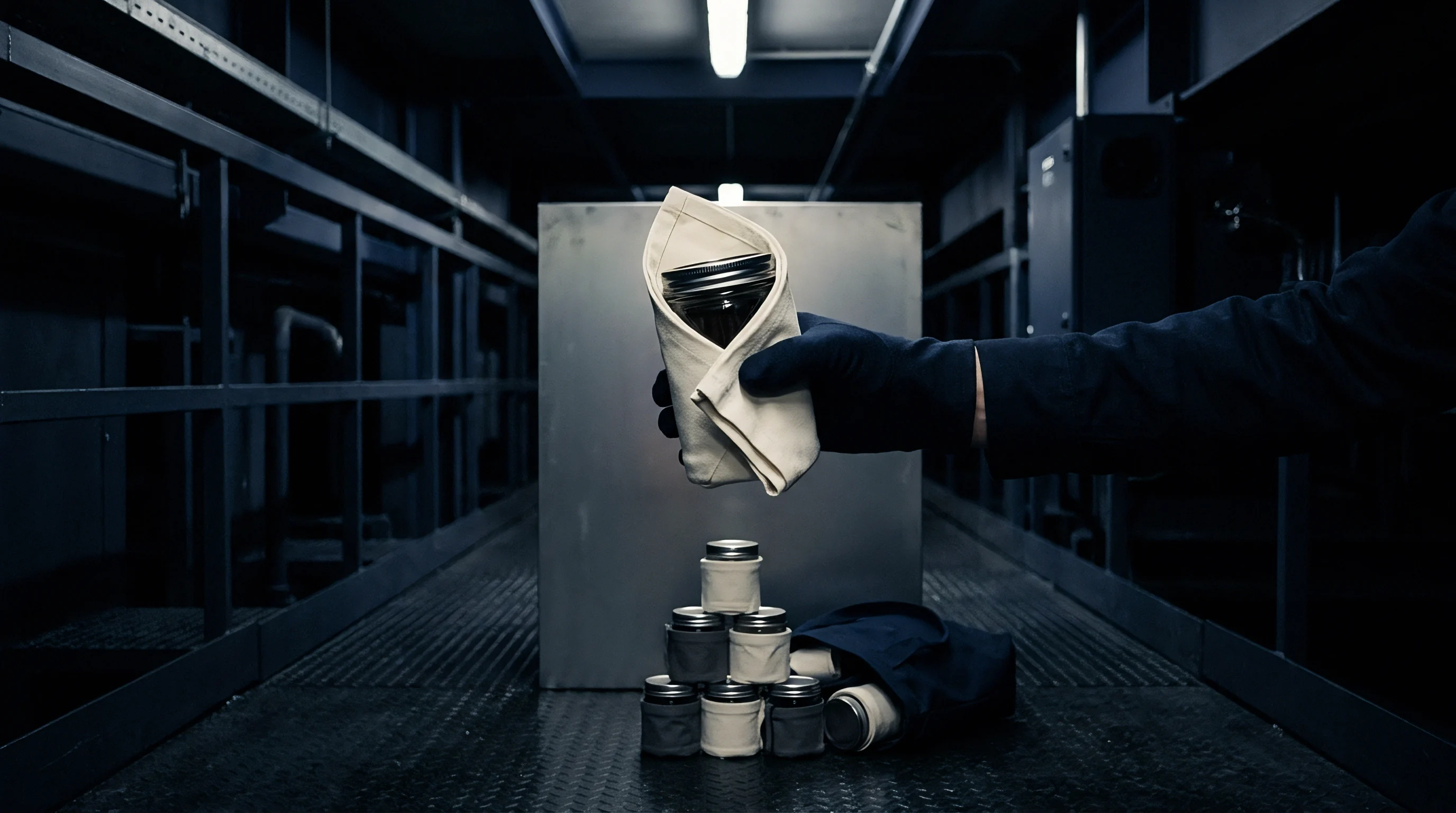
Subjecting production batches to a minimum of fifty deep thermal exposures eliminates early-life diaphragm failures before shipment. Screening records show that un-screened submicroliter sensor lots suffer up to eighteen percent field reject rates due to zero-point drift when installed on cryogenic containment systems.
Implementing mandatory burn-in procedures alters unit delivery economics. The sequence below outlines the acceptance verification protocol necessary to guarantee long-term dimensional stability for submicroliter oil fill pressure cells.
- Initial baseline zero and full-scale calibration at +23 °C inside a controlled environmental chamber.
- Rapid liquid nitrogen immersion bringing core temperature to -196 °C with thirty minutes minimum dwell.
- Direct thermal transfer to +85 °C heated air stream to complete one full thermal shock transition.
- Repetition of thermal shock sequence for fifty consecutive uninterrupted cycles.
- Stabilization at room ambient conditions for twenty-four hours to relieve residual metallic strain.
- Final baseline post-test calibration to evaluate cumulative zero offset drift and span stability.
Cost Trade-Offs in Ultra-Stable Cavity Manufacturing
Machining submillimeter housing features out of Invar or specialized titanium alloys increases baseline machining expense by three hundred percent compared to standard stainless steel housings. Specialized vacuum oil-filling rigs capable of dosing cavities below 0.1 microliters with ±0.01 microliter precision require substantial capital investments.
Buyers evaluating supply options must weigh initial unit acquisition cost against long-term calibration and replacement expenditures over a multi-year service cycle.
Initial unit price increases by approximately 240 percent when moving from standard industrial tolerances to cryogenically burn-in screened sensors.
As a practical rule of thumb, purchasing unscreened sensors for cryogenic service saves initial acquisition capital while tripling five-year ownership costs through field re-calibration overhead and unscheduled downtime.


Boundary
Operational envelopes for oil-filled micro-cavities remain constrained by physical phase transitions and material thermal expansion mismatches. Continuous exposure to deep thermal cycling tests the theoretical limits of fluid-filled pressure sensing architectures. Glass transition locks fluid.
Thermal shock accelerates microcracking.

Limits of Silicone Fluid Viscoelasticity
Glass transition transitions occur in dimethyl silicone fluids between minus one hundred twenty and minus one hundred thirty-five degrees Celsius. Below this glass transition floor, fluid viscosity rises toward infinity, transforming the liquid into a rigid solid. Hydrostatic pressure transmission becomes anisotropic, generating shear vectors that distort sensing die strain bridges.
Advanced low-viscosity hydrocarbon and halogenated fill fluids extend liquid state compliance into deeper thermal zones, yet non-linear volumetric thermal contraction continues to impose geometric boundaries on micro-cavity design.
What structural modifications to submicroliter internal void geometries will finally allow oil-filled sensors to achieve zero thermal hysteresis down to absolute zero remain open to active laboratory research.