Inertial Sensor Thermal Calibration Techniques during Stationary Alignment
Dynamic thermal calibration during stationary alignment resolves internal heating gradients using multi-point rate-of-change modeling to secure true north.


Gradient
Temperature gradients across an inertial measurement unit warp its structural frame and distort pickoff geometries. During stationary initialization, the system levels its pitch and roll axes against gravity before gyrocompassing to resolve true north. That process isolates the horizontal component of Earth rotation ~ roughly 15.041 degrees per hour scaled by the cosine of latitude.
At high latitudes, where this horizontal vector contracts, the sensor noise floor and uncompensated bias must stay below 0.01 degrees per hour for heading to converge within ten minutes. Uneven heat disrupts that convergence. Local dissipation produces thermal gradients across quartz flexures, optical fiber coils, and silicon resonating beams, generating stresses that sensors read as true rotation.
A cold start alters baseline zero offsets before internal thermal equilibrium is reached.
In precision fiber optic gyroscopes, transient temperature differentials drive the Shupe effect ~ non-reciprocal optical phase shifts within the coil. When heat diffuses through a quadrupole-wound pack, counter-propagating beams encounter differing refractive indices over identical geometric paths, producing a phase mismatch that the instrument interprets as physical rotation. The magnitude of this false rate tracks both the thermal gradient across spool layers and how quickly that gradient changes.
Accelerometers in the same cluster face comparable issues: asymmetric conduction across the instrument body expands suspension arms unevenly, tilting the proof mass and injecting a false acceleration bias along the input axis that skews the initial tilt solution.
Asymmetric Heat Distribution in Gyroscopic Coils
Directional heat flux from nearby power supplies produces uneven refractive index distributions across wound optical fiber. Quadrupole winding places turns symmetrically around the midpoint to neutralize linear radial gradients, but conductive paths from mounting feet or neighboring DC-DC converters break that symmetry. Axial and circumferential heat flows then create net phase offsets.
An uncompensated tactical-grade instrument with a 1,000-meter coil subject to a gradient of 0.1 degrees Celsius per minute can produce an apparent rate above 0.05 degrees per hour, skewing the calculated meridian directly off true north.
Thermal lag across the assembly corrupts the resolved Earth rate vector during alignment.
| Transduction Principle | Dominant Thermal Mechanism | Uncompensated Bias Drift Rate | Thermal Settling Time | Alignment Heading Limit |
|---|---|---|---|---|
| Fiber Optic Gyroscope Quadrupole Coil | Shupe phase asymmetry across spool layers | 0.01 to 0.10 deg/hr per deg C/min | 25 to 45 minutes | 0.05 to 0.20 deg secant latitude |
| Ring Laser Gyroscope Monolithic Cavity | Anisotropic Zerodur expansion and gas convection | 0.002 to 0.015 deg/hr steady state | 5 to 12 minutes | 0.01 to 0.05 deg secant latitude |
| Quartz Resonant Coriolis Vibratory Gyro | Thermoelastic stress on tuning fork tine stems | 0.50 to 3.00 deg/hr per deg C | 10 to 20 minutes | 0.50 to 1.50 deg secant latitude |
| Silicon Capacitive MEMS Proof Mass | Asymmetric flexure expansion and die stress | 5.00 to 30.00 deg/hr per deg C | 3 to 8 minutes | Unsuitable for gyrocompassing |
| Quartz Flexure Accelerometer | Bending moment variation across mounting bridge | 15 to 80 micro-g per deg C | 15 to 30 minutes | 0.02 to 0.08 deg leveling tilt error |

Earth Rate Projection Errors during Stationary Gyrocompassing
Finding true north requires separating planetary rotation of 15.041 degrees per hour from instrument drift. With the platform level, an east-oriented gyro should ideally see zero rotation; any residual bias mimics an eastward rate component and pulls the calculated azimuth away from the meridian. Accelerometer tilt errors compound the problem.
A horizontal accelerometer bias of 50 micro-g produces roughly 10 arcseconds of leveling error, which projects the vertical component of Earth rate directly into the horizontal plane.
- Transient Shupe Phase Imbalance occurs when localized heat conduction establishes non-reciprocal transit delays between clockwise and counter-clockwise optical paths before thermal equilibrium settles.
- Thermoelastic Suspension Warpage develops when mounting pads expand unevenly against the chassis, exerting parasitic bending moments across quartz hinge structures.
- Piezoresistive Bridge Thermal Drift unbalances bridge excitation in silicon pickoffs, generating millivolt-level output shifts that downstream stages digitize as angular rate.
- Die Attach Adhesive Plasticity softens under operational heating, shifting the die against its reference pins and rotating the sensitive axis during alignment.
Uncorrected thermal gradients during leveling and gyrocompassing leave residual tilt errors that carry directly into the azimuth solution, often leaving a permanent heading error greater than several tenths of a degree.

Heat
On startup, internal electronics dump heat directly into the aluminum or titanium chassis. Processors, converters, and FPGAs draw several watts immediately upon power-up, turning the structural block into an active thermal environment with steep gradients and sharp localized heating. This rapid flux occurs precisely during the initial window reserved for stationary alignment.
Passive conduction requires twenty to forty minutes to reach steady state, yet operational profiles routinely demand a valid heading within five minutes of cold start.
Resolving true north requires angular precision on the order of micro-radians.
Fiber optic gyro bias instability rises from 0.005 degrees per hour at thermal equilibrium to 0.08 degrees per hour during a two degree per minute temperature slew.
Does Internal Heating Distort Initial Azimuth?
Regulator heat creates localized strains throughout the structural block. Following a cold start at minus forty degrees Celsius, internal chassis temperatures climb at 0.5 to 3.0 degrees Celsius per minute over the first eight minutes. Dynamic errors induced over this interval exceed static calibration values by an order of magnitude.
Standard calibration polynomials calculate bias purely against instantaneous temperature under the assumption of thermodynamic equilibrium, which rapid warmup completely invalidates. Because the resonant core lags behind the exterior chassis thermistor by several degrees, static lookup curves fail to capture the true sensor state.
External thermistors monitor structural conduction rather than internal die conditions.

Rate-of-Change Compensation in Bias Polynomials
Adding temperature derivatives to the compensation routine bridges the lag between outer packaging and isolated sensing dies. By including the first derivative of temperature with respect to time, the model absorbs much of this transient stress. A typical multi-variable formulation expresses sensor bias as:
B(T, dT/dt) = a0 + a1 T + a2 T^2 + a3 T^3 + b1 (dT/dt) + b2 (dT/dt)^2 + c1 T (dT/dt)
In this formulation, a0 through a3 serve as static thermal coefficients, b1 and b2 model transient slew responses, and c1 handles cross-coupling between absolute temperature and rate of change. Adding these dynamic terms cuts warm-up bias wander by 75 to 90 percent in tactical-grade units. Calculating dT/dt, however, requires clean temperature measurements.
Digitizing raw thermistor voltages with twelve-bit converters introduces quantization jitter that numerical differentiation turns into high-frequency rate noise. Digital low-pass filtering or Savitzky-Golay smoothing suppresses these derivative spikes without washing out real thermal trends.
- Power Activation and Dielectric Initialization draws immediate current into converters and logic devices, propagating conductive heat toward the sensor mounts.
- Spatial Thermal Wave Propagation induces mechanical stress across the instrument block, changing mounting compliance before perimeter thermistors detect the core temperature rise.
- Dynamic Derivative Extraction computes numerical derivatives from multi-point arrays using five-point moving polynomial windows to keep differentiation noise out of the compensation stream.
- Polynomial Real-Time Subtraction computes static and transient corrections in FPGA firmware before delivering inertial data to the alignment filter.
A thermistor on the chassis tracks outer ambient swings, but only an element bonded near the proof mass captures actual structural expansion.
Array
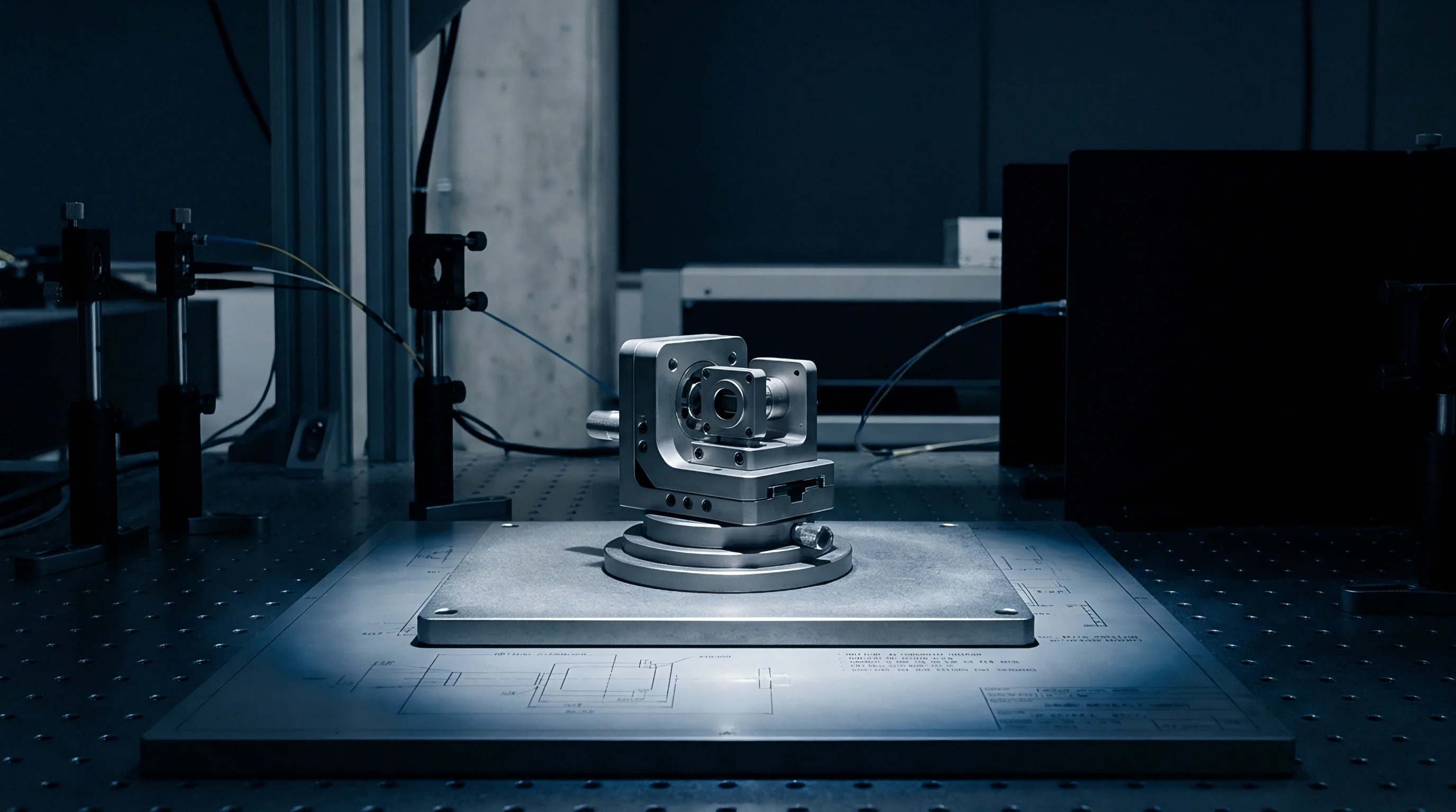
Mapping conduction paths across the sensor block requires several thermistors. Relying on one temperature measurement across a three-axis cluster leaves large residual errors, because internal heat sources sit closer to some sensors than others. A power converter near the z-axis gyro heats that channel immediately, whereas thermal energy reaches the horizontal axes only after a noticeable conduction delay.
Placing miniature platinum RTDs or calibrated diodes at distinct locations allows the compensation engine to reconstruct internal gradients in real time.
Symmetric structural packaging dissipates internal thermal gradients faster than electronic compensation can model them.
Will in Situ Residual Modeling Suppress Wander?
Augmenting the baseline alignment state vector allows the filter to estimate attitude errors and unmodeled drift at the same time. Standard stationary Kalman filters track tilt errors, azimuth mispointing, and fixed sensor biases, but assuming constant bias fails when internal gradients produce time-varying drift. Expanding the state vector to include thermal states tied to live temperature inputs lets the estimator track that dynamic drift during stationary alignment, linking gyro bias states directly to real-time thermistor outputs.
Kalman alignment routines require true physical residuals rather than thermally distorted innovations.
| Compensation Architecture | Physical Implementation | Computational Load | Calibration Cost | Residual Bias Suppression |
|---|---|---|---|---|
| Single-Point Static Polynomial | Single thermistor on internal chassis; static polynomial lookup table | Low: 10 floating-point operations per sample cycle | Low: single static temperature chamber run per axis | Poor during warm-up: 60 to 70 percent residual drift remains |
| Multi-Point Dynamic Derivative | Four to six thermistors distributed at ASIC, coil, and chassis zones | Moderate: 80 floating-point operations with digital filtering | Moderate: multi-rate temperature ramps required | Good: 85 to 92 percent suppression of warm-up drift |
| In Situ Augmented Kalman Filter | Array monitoring fed into alignment state matrix as dynamic states | High: matrix inversions scaled to augmented state dimensions | Low: relies on filter convergence rather than chamber mapping | Moderate to high: dependent on platform excitation and duration |
| Active Indexing Rotation | Single-axis or two-axis indexing table rotating sensor cluster | Moderate: coordinate transformations and motor control logic | Very high: precision mechanical turntable hardware required | Superior: 98 percent suppression via physical axis reversal |

Multi-Position Indexing Sequences on Stationary Mounts
Rotating the sensor cluster through precise 180-degree steps inverts the sensitive axes against gravity, isolating instrument bias from environmental inputs without depending strictly on thermal models. An upward-pointing accelerometer measures negative gravity plus its thermal bias; inverted by 180 degrees, it measures positive gravity plus that same bias. Summing the two readings cancels gravity and isolates the bias, while subtracting them isolates gravity.
The same rotational reversal separates gyro bias from horizontal Earth rate.
Continuous single-axis rotation during alignment modulates horizontal Earth rate onto a sinusoidal carrier. By demodulating above zero hertz, the navigation algorithm moves the alignment signal away from 1/f flicker noise and low-frequency thermal drift. Standard in marine navigators and precision survey equipment, this approach reduces the need for exhaustive chamber calibration of individual units, though slip rings, torque motors, and encoders shift development costs into mechanical hardware.
Decoupling higher-order gradient effects from stochastic sensor flicker noise remains difficult without extending stationary alignment well past operational limits.

Chamber
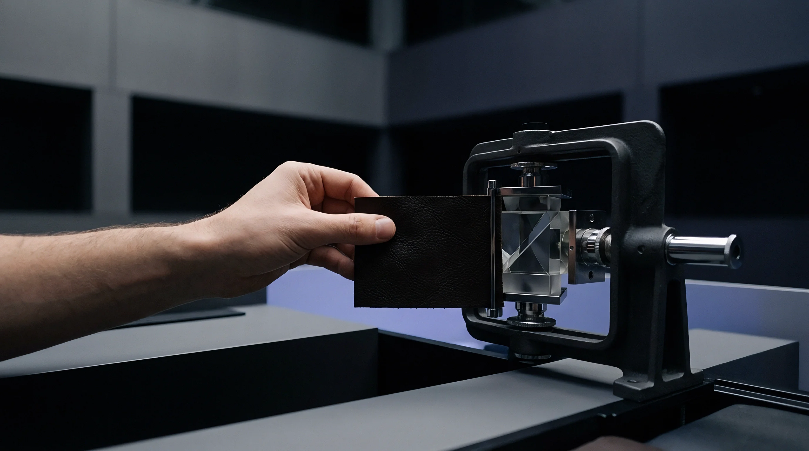
Oven testing establishes baseline polynomial coefficients across the operating range from minus forty to plus eighty-five degrees Celsius. Technicians mount the inertial package on a multi-axis rate table inside an environmental chamber, cycling the hardware through temperature plateaus linked by controlled ramps. This run maps scale factor, cross-axis alignment, and zero-rate bias across the thermal range.
Unmodeled transient ramps slow and degrade heading convergence during field alignment.
Thermal expansion in quartz accelerometer flexures generates mechanical torque indistinguishable from true kinematic acceleration.

Static Soak against Dynamic Slew Calibration
Coefficients derived from steady-state dwells differ systematically from those measured during dynamic ramps of two degrees per minute. In static profiling, the chamber pauses at temperatures like minus forty, zero, twenty-five, fifty-five, and eighty-five degrees Celsius for several hours. Only when internal sensors confirm steady state does the table execute rate steps and static tumbles, capturing equilibrium behavior.
In practice, however, stationary alignment happens almost entirely during non-equilibrium conditions, meaning static profiles leave substantial residual error during rapid field turn-on.
Shupe-induced optical phase shifts produce rate signals identical to platform motion.

Hysteresis Verification across Thermal Profiles
Sensors tested on rising temperature sweeps produce different outputs than when measured at the same temperatures on cooling sweeps. This hysteresis originates in stress relaxation within structural brazes, die-attach adhesives, and quartz crystalline structures. Fitting a standard second-order polynomial to an averaged profile splits the difference between the heating and cooling curves, leaving an uncompensated loop.
Tactical-grade instruments show bias hysteresis loops between 0.05 and 0.20 degrees per hour in gyros and 50 to 150 micro-g in accelerometers. Aligning a warm unit right after shutdown follows a cooling trajectory that produces bias errors opposite to those seen during a cold start.
| Calibration Methodology | Thermal Profile Profile Duration | Chamber Equipment Required | Landed Unit Test Cost | Residual Bias Uncertainty |
|---|---|---|---|---|
| Three-Point Static Plateau | 6 hours total soak time | Standard thermal oven with manual tilt fixture | 120 to 180 USD | 0.15 deg/hr; 200 micro-g |
| Nine-Point Multi-Rate Ramp | 24 to 36 hours continuous | Two-axis rate table inside liquid nitrogen chamber | 650 to 950 USD | 0.02 deg/hr; 30 micro-g |
| Bidirectional Hysteresis Map | 48 to 72 hours dual cycles | Precision rate table with multi-zone thermal shroud | 1,400 to 2,200 USD | 0.005 deg/hr; 10 micro-g |
- Temperature Profiling Specifications set the ramp rates, soak times, and plateau thresholds used for environmental acceptance.
- Sensor Serialization Metadata preserves individual polynomial matrices, residual variance logs, and raw chamber timestamps for each serial number.
- Thermistor Coordinate Mapping logs the physical location and mounting method for each temperature sensor on the structural chassis.
- Residual Error Verification Boundaries define pass-fail thresholds for residual bias drift across both stationary warm-up and dynamic slew runs.
Environmental slew rates exceeding one degree per minute sit outside standard factory limits, shifting thermal isolation requirements onto system integrators.

Audit
Procurement specifications require direct verification of drift limits under fast thermal transitions. Datasheets routinely showcase bias stability measured at steady room temperature after a sixty-minute soak. Field applications, by contrast, demand inspecting acceptance test records to verify that factory profiling matches real turn-on conditions.
A unit claiming 0.01 degrees per hour bias instability from an Allan variance test at twenty degrees Celsius can easily experience 0.50 degrees per hour of drift when warming up from a cold start.
Compliance with IEEE 1299 environmental profiling mandates that thermal transient testing include bidirectional thermal ramps to quantify sensor hysteresis.
Contractual Tolerances for Inertial Run-Up Stability
Procurement contracts define heading error limits within five minutes of cold start. Typical specification language often errs by quoting drift over long operational spans rather than during the critical run-up window. Defining this envelope properly requires specifying initial temperature, airflow, allowed warmup time, and acceptable azimuth variance.
Compliance verification then tests alignment while the package undergoes an unconditioned ramp driven solely by internal electronics.

Yield Exposure in Commercial Sensor Qualification
Production testing shows that roughly fifteen percent of uncompensated dies fail demanding gyrocompassing limits. These fallouts exhibit excessive hysteresis or structural stress coupling that static polynomial models cannot correct. Imposing tight transient limits without adjusting pricing forces manufacturers to scrap parts, extending lead times and increasing unit costs.
Contracts protect schedules by setting process capability indices for thermal coefficients rather than relying on technicians to hand-tune outliers through screening.
Invoking IEEE 952 clause 6.4 in the contract requires delivery of raw third-order polynomial residuals alongside thermal hysteresis curves for every serialized unit.