Quantifying Reference Uncertainty in High Temperature MEMS Calibration
Quantifying high-temperature MEMS calibration uncertainty demands summing reference sensor error, furnace thermal gradients, and package drift into expanded limits.


Probe
Secondary temperature standards operating above five hundred degrees Celsius depend on platinum resistance elements or noble metal thermoelements. In high temperature microelectromechanical systems (MEMS) calibration, the reference probe’s accuracy sets the hard floor for the entire measurement process. Standard industrial thermocouples drift within tens of hours at eight hundred degrees Celsius as selective oxidation, grain growth, and chemical contaminants alter the thermoelectric wires.
When high temperature MEMS piezoresistive pressure sensors and capacitive accelerometers are calibrated against an unstable reference, those baseline errors transfer straight into the device’s operational ratings.
Choosing a workable transfer standard involves weighing thermal response against mechanical stability and calibration drift. Standard Platinum Resistance Thermometers (SPRTs) in quartz or platinum sheaths deliver the lowest uncertainty up to six hundred sixty degrees Celsius, reaching uncertainties as narrow as plus or minus zero point zero05 degrees Celsius with careful handling. Past six hundred sixty degrees Celsius, however, high-purity platinum softens, causing strain-induced resistance shifts that degrade accuracy.
Noble metal thermocouples, specifically Type S (Platinum-10% Rhodium versus Platinum) and Type R (Platinum-13% Rhodium versus Platinum), serve as the main transfer standards up to eleven hundred degrees Celsius, though with wider baseline uncertainty than resistance thermometers.
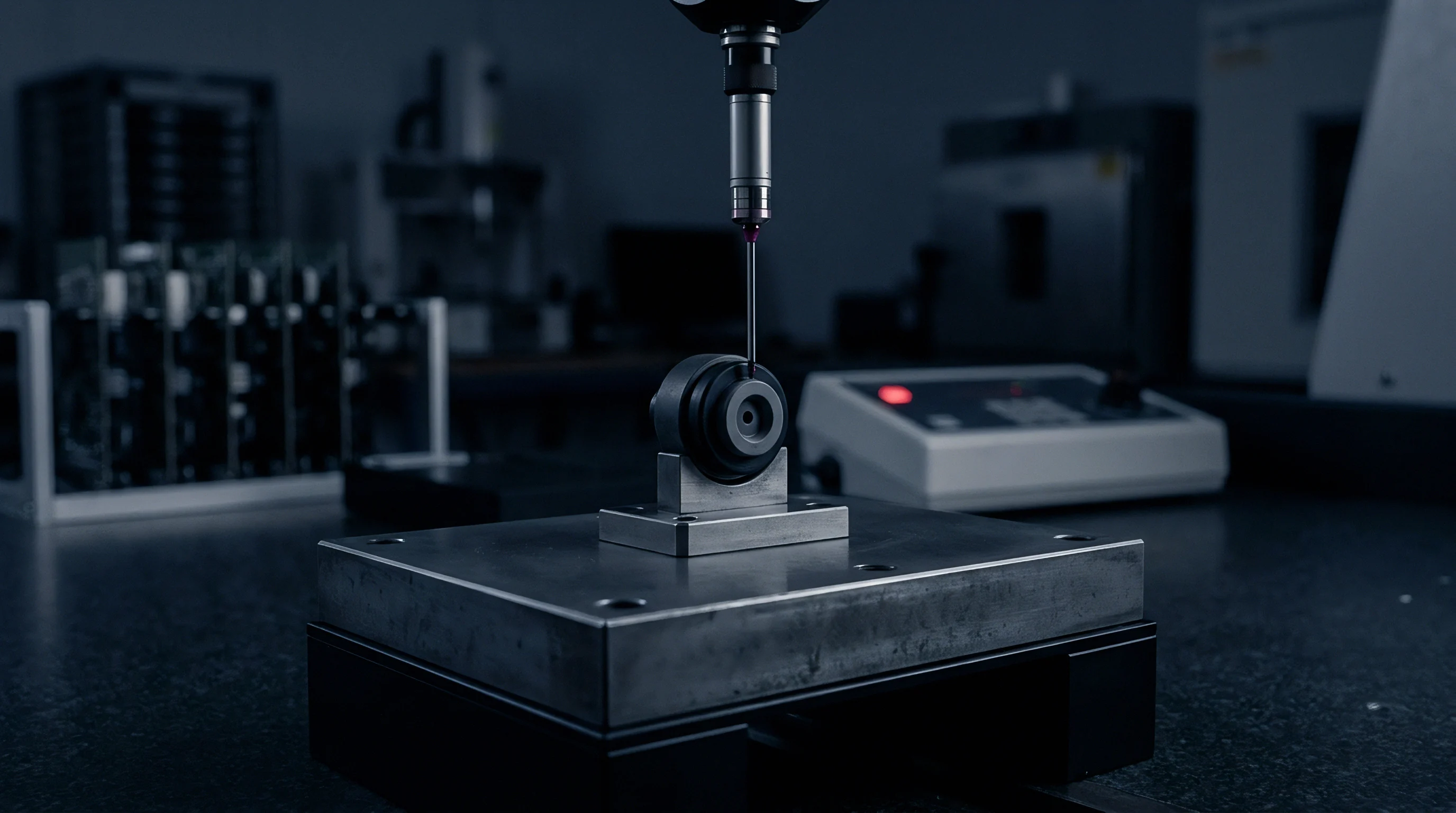
Secondary Reference Selection for Extreme Environment Sourcing
Matching sensor response time to the thermal mass of the reference standard is critical during MEMS pressure and acceleration testing. Bulky ceramic-sheathed thermocouples equilibrate slowly, generating lag errors during thermal ramps. Thin-sheathed mineral-insulated metal-sheathed (MIMS) thermocouples react quickly, but they drift faster at extreme temperatures because of catalytic reactions and thermoelement contamination.
Sapphire light-pipe optical pyrometers avoid thermal mass problems by measuring temperature optically above one thousand degrees Celsius, but their uncertainty budgets depend heavily on target surface emissivity variations and optical window fouling.
Narrower uncertainty bounds come at substantial operating expense.
Calibration labs balance achievable uncertainty against probe lifespan when setting up high temperature MEMS test lines. A calibrated Type S thermocouple held continuously at nine hundred degrees Celsius drifts by zero point two to zero point five degrees Celsius per hundred hours of thermal exposure. Servicing or replacing reference probes on schedule forms a major operational cost that facilities have to absorb.
A Standard Platinum Resistance Thermometer exhibits a baseline reference uncertainty of plus or minus zero point zero five degrees Celsius at eight hundred degrees Celsius when immersed to a minimum depth of fifteen centimeters in an isothermal equalization block.
Traceability Structures from National Metrology Institutes
Accredited calibration certificates tie shop-floor measurements back to the International System of Units. For high temperature MEMS reference probes, this traceability chain starts at National Metrology Institutes (NMIs) like NIST or PTB, where primary standards are referenced against fixed points on the International Temperature Scale of 1990 (ITS-90), including the freezing points of aluminum (six hundred sixty point three two three degrees Celsius) and silver (nine hundred sixty one point seven eight degrees Celsius). Secondary calibration laboratories transfer these fixed-point calibrations to working reference probes using comparison calibration techniques in isothermal bath or furnace environments.
Every transfer along the chain widens the combined uncertainty. An NMI primary standard operating at the silver point holds an expanded uncertainty (k=2) of approximately zero point zero one5 degrees Celsius. The secondary laboratory transfer probe calibrated against that primary standard carries an expanded uncertainty of zero point zero eight degrees Celsius.
By the time a working reference probe is positioned inside a commercial MEMS calibration furnace alongside a device under test, the baseline temperature reference uncertainty expands to plus or minus zero point three to zero point five degrees Celsius, even before accounting for furnace thermal gradients and fixture mounting losses. Overlooking probe immersion depth under these conditions introduces static thermal offsets that ruin entire sensor manufacturing batches.


Soak
High temperature thermal chambers produce substantial spatial temperature variations that distort calibration data. Multi-zone resistive heaters, thick metallic equalization blocks, and heat pipes help flatten gradients across the working volume, but differences of one to three degrees Celsius across a ten-centimeter calibration zone remain common in high temperature testing fixtures. If the reference probe and the MEMS device under test sit at different points within that span, the local gradient translates directly into an uncorrected measurement bias.
Radiant heat transfer dominates chamber dynamics at eight hundred degrees Celsius.
Furnace wall emission, viewing port reflections, and emissivity differences between the reference probe sheath and the MEMS sensor package create significant radiative thermal imbalances. A polished metallic MEMS package reflects ambient thermal radiation differently than a matte ceramic reference probe sheath. As a result, the micromachined sensing structure can settle at a different thermal equilibrium temperature than the reference instrument reads, even when both sit in identical gas-phase temperatures.

Chamber Thermal Gradients and Radiant Heat Offsets
Accounting for radiant offsets requires measuring chamber wall emissivity and modeling radiative exchange factors across the hot zone. Inside a multi-zone tube furnace operating at nine hundred degrees Celsius, a ten percent mismatch in surface emissivity between the reference probe and the MEMS package induces a temperature offset of up to one point two degrees Celsius under typical convective flow rates. Placing both the reference probe and the MEMS package inside a high-purity nickel or platinum equalization block dampens radiant imbalances by ensuring that all surrounding surfaces radiate as a uniform blackbody enclosure.
Control loop stability over time introduces another major uncertainty layer during thermal soak testing. Furnace temperature controllers oscillate around their setpoint in response to power modulation cycles. A furnace temperature control stability of plus or minus zero point two degrees Celsius creates continuous phase-lagged thermal waves through the test fixture.
Because the MEMS sensing element typically possesses a much smaller thermal mass than the secondary reference probe, the MEMS device tracks the dynamic temperature fluctuation rapidly while the reference probe filters and lags behind the temperature swing, creating time-dependent measurement discrepancies.

Stem Conduction Loss in High Temperature Test Fixtures
Heat escaping outward along the metallic sheath of a sensor lowers the active sensing element temperature relative to the surrounding gas or block. This stem conduction loss scales with the overall thermal gradient and drops inversely with the square root of immersion depth. In high temperature MEMS test setups, mechanical space constraints inside the calibration chamber frequently force engineers to reduce probe immersion depths below manufacturer recommendations.
Unchecked stem conduction pulls junction temperatures well below the true zone average.
When a thermocouple probe with a six-millimeter outer sheath diameter is immersed to only five sheath diameters inside an eight-hundred-degree furnace zone, heat conduction along the sheath draws energy away from the measuring junction, resulting in a temperature reading that sits five to twelve degrees Celsius below the true zone temperature. Correcting stem conduction requires enforcing a minimum immersion depth of fifteen to twenty sheath diameters or installing active heat-shielding collars along the probe stem.
High-temperature calibration fixtures routinely encounter several distinct spatial and thermal failure modes:
- Spatial thermal non-uniformity across the calibration block volume creates uncorrected temperature offsets between reference instruments and sensors under test.
- Radiative surface emissivity mismatch between polished metal sensor packages and oxidized ceramic reference sheaths induces radiant heat transfer biases.
- Immersion depth deficiency along sensor sheaths permits heat conduction to external ambient air, depressing measured junction temperatures.
- Convective air turbulence inside unsealed furnace chambers induces localized thermal fluctuations across delicate MEMS sensing diaphragms.
High-temperature calibration discrepancies frequently stem from internal reference probe drift rather than furnace gradients.

Matrix
Constructing a rigorous error model for high temperature MEMS characterization relies on root-sum-square summation across all individual uncertainty contributors. In accordance with the Guide to the Expression of Uncertainty in Measurement (JCGM 100:2008), every potential source of measurement error must be identified, quantified as a standard uncertainty (standard deviation), and transformed through sensitivity coefficients before combination. For high temperature MEMS pressure calibration, the combined standard uncertainty of the reference system incorporates reference probe calibration error, reference probe long-term drift, furnace spatial non-uniformity, furnace temporal instability, stem conduction losses, signal conditioning electronics noise, and pressure reference uncertainty.
Shared physical dependencies between measurement variables inflate combined uncertainty through non-zero covariance.
Whenever two uncertainty components share a common physical cause, such as temperature variations simultaneously altering pressure reference output and MEMS piezoresistive bridge balance, their mutual covariance term must be included in the combined uncertainty equation. Neglecting correlation terms leads to severe underestimation of total measurement uncertainty.

Uncertainty Budget Architecture under Standard Guides
Evaluating standard uncertainties involves classifying each contributor into Type A (evaluated by statistical analysis of series of observations) or Type B (evaluated by scientific judgment using manufacturer specifications, calibration certificates, or physical models). For high temperature MEMS calibration, Type A evaluation covers repeat measurements of zero-point offset and span sensitivity under stable furnace conditions. Type B evaluation dominates the remaining budget, covering reference probe certificate figures, chamber thermal gradient estimates, and electrical acquisition hardware specs.
To demonstrate the mathematical construction of a high temperature MEMS pressure sensor uncertainty budget, consider a piezoresistive silicon carbide pressure sensor calibrated at six hundred degrees Celsius and one megapascal applied pressure. Assume the following operational parameters and Type B uncertainty inputs:
The reference Type S thermocouple carries a expanded calibration certificate uncertainty of zero point four zero degrees Celsius (k=2), yielding a standard uncertainty u_1 of zero point two zero degrees Celsius.
The furnace spatial gradient across the equalization block is measured at zero point six zero degrees Celsius with a rectangular probability distribution, yielding a standard uncertainty u_2 = 0.60 / sqrt(3) = zero point three five degrees Celsius.
The furnace temporal oscillation is zero point two zero degrees Celsius with a Gaussian distribution, giving u_3 = zero point two zero degrees Celsius.
The pressure transfer standard carries an expanded calibration uncertainty of zero point five kilopascals (k=2), giving a standard uncertainty u_4 of zero point two five kilopascals.
The MEMS pressure sensor thermal sensitivity coefficient (alpha) is zero point one five kilopascals per degree Celsius.
The standard uncertainty contribution from temperature errors converted into equivalent pressure units is u_temp = alpha sqrt(u_1^2 + u_2^2 + u_3^2) = 0.15 sqrt(0.20^2 + 0.35^2 + 0.20^2) = 0.15 0.45 = zero point zero six8 kilopascals.
Combining the temperature-induced pressure uncertainty with the pressure reference uncertainty u_4 yields the combined standard uncertainty u_c = sqrt(u_temp^2 + u_4^2) = sqrt(0.068^2 + 0.25^2) = zero point two five nine kilopascals.
Applying a coverage factor k=2 yields an expanded combined reference uncertainty U = zero point five two kilopascals at a ninety-five percent confidence level.
Covariance Terms in Combined Multi-Factor Calibration
Cross-sensitivity between applied mechanical stress and furnace thermal fluctuation creates correlated error terms during simultaneous excitation. If temperature changes cause proportional thermal expansion in the pressure media tube, modulating the local pressure delivered to the MEMS diaphragm, the covariance between temperature measurement error and applied pressure measurement error must be explicitly computed using partial derivatives of the functional measurement equation.
Clause 7.8.4 of ISO/IEC 17025 obligates calibration laboratories to include reported measurement uncertainty explicitly within certificate documentation or forfeit international accreditation traceability.
Reference sensors operating in an eight-hundred-degree Celsius calibration cell exhibit different baseline and combined uncertainties depending on their physical construction:
| Reference Sensor Type | Base Calibration Uncertainty | 100-Hour Thermal Drift | Spatial Gradient Uncertainty | Expanded Combined Uncertainty (k=2) |
|---|---|---|---|---|
| Type S Thermocouple (Platinum/Rhodium) | +/- 0.35 °C | +/- 0.25 °C | +/- 0.45 °C | +/- 1.22 °C |
| Type N Thermocouple (Nicrosil/Nisil) | +/- 0.65 °C | +/- 0.40 °C | +/- 0.45 °C | +/- 1.78 °C |
| High-Temp SPRT (Quartz Sheath) | +/- 0.08 °C | +/- 0.12 °C | +/- 0.20 °C | +/- 0.50 °C |
| Sapphire Optical Pyrometer | +/- 1.20 °C | +/- 0.15 °C | +/- 0.80 °C | +/- 2.92 °C |
| Methods note: Standard coverage factor k=2 applied across all values assuming normal distribution of combined error sources inside an isothermal equalization block. | ||||
Auditing prospective sensor suppliers requires inspecting their calibration fixtures and reviewing their uncertainty calculation sheets. Buyers verify compliance by demanding line-item uncertainty budgets prior to placing production purchase orders.
A complete supplier uncertainty dossier should detail several core validation parameters:
- Expanded uncertainty statement clearly identifying the applied coverage factor and associated confidence interval level.
- Coverage factor verification demonstrating whether k=2 or k=3 was selected based on effective degrees of freedom calculated via the Welch-Satterthwaite equation.
- Thermal stability duration explicitly defining the maximum allowable furnace soak time before reference re-calibration is required.
- Hysteresis loop logging documenting sensor output divergence during continuous ascending and descending temperature ramps.
Standard specification clauses aligned with JCGM 100:2008 clause 6.2 enforce expanded uncertainty reporting at a ninety-five percent confidence level, preventing suppliers from hiding component variability behind bare standard deviation figures.

Decay
Microelectromechanical structures held at high temperatures undergo structural and electrical drift driven by atomic diffusion, grain relaxation, and internal strain relief. In piezoresistive MEMS pressure sensors, high temperature exposure induces dopant migration within silicon piezoresistors, altering baseline electrical resistance and modifying the temperature coefficient of resistance (TCR). Capacitive MEMS accelerometers experience mechanical creep in silicon spring structures and dielectric degradation in high-temperature isolation layers, leading to continuous zero-g bias drift during extended service life.
Material degradation inside the sensing cell shifts scale factor and zero-point calibration during extended operation.
Decay mechanics operating within the sensor packaging often eclipse the drift of the MEMS element itself. Differential thermal expansion between the silicon MEMS die, metallic glass braze materials, and ceramic substrates generates high residual mechanical stress. Over hundreds of operating hours at six hundred degrees Celsius, micro-yielding of metallic brazes and stress relaxation in glass frits relieve this internal strain, causing a slow, monotonic shift in the sensor zero-pressure output voltage.

What Residual Drift Remains after High Temperature Soak?
Unrecoverable zero-point shifts persist even after sensors return to ambient room temperature following an extended heat cycle. Thermal hysteresis represents the difference in sensor output at room temperature measured before and after a high temperature excursion. In silicon carbide MEMS pressure sensors operating above seven hundred degrees Celsius, hysteresis loops stem from irreversible phase changes in electrical contact metallization, such as nickel silicide contact degradation, and micro-crack formation in ceramic packaging headers.
Wide-bandgap silicon carbide substrates substantially curb intrinsic high-temperature semiconductor drift.
Quantifying thermal hysteresis requires running standardized thermal cycling profiles where sensors undergo multiple heating and cooling runs between ambient temperature and maximum rated operating temperature. A MEMS sensor exhibiting zero point five percent full-scale output hysteresis over a single thermal cycle will compound baseline measurement error if field applications involve repeated thermal shutdown and startup cycles.
Thermal hysteresis accumulated during cooling cycles sets the actual floor of sensor measurement repeatability in extreme service environments.
Substrate Grain Growth and Piezoresistive Metallization Shift
Polysilicon and single-crystal silicon piezoresistors experience dopant migration and contact resistance alteration at sustained high thermal thresholds. Titanium-platinum-gold contact pads deposited on silicon sensing elements undergo interdiffusion at temperatures exceeding four hundred fifty degrees Celsius, forming high-resistance intermetallic compounds that degrade signal-to-noise ratios and introduce unpredictable thermal zero shift.
The following performance data illustrates typical drift rates and degradation modes for common MEMS materials held at temperature for one thousand hours:
| Substrate / Packaging Combination | Test Temperature | Zero-Point Drift (% Full Scale) | Sensitivity Drift (% Reading) | Dominant Physical Degradation Mechanism |
|---|---|---|---|---|
| Silicon-on-Insulator (SOI) / Glass Frit Seal | 500 °C | 1.15 % | 0.85 % | Glass frit mechanical stress relaxation |
| Silicon Carbide (4H-SiC) / Gold-Germanium Braze | 600 °C | 0.35 % | 0.20 % | Ohmic contact interdiffusion |
| Polysilicon on Steel / Ceramic Header | 450 °C | 2.40 % | 1.60 % | Substrate grain boundary oxide growth |
| Sapphire Substrate / Platinum Metallization | 800 °C | 0.18 % | 0.12 % | Substrate-to-film CTE thermal mismatch strain |
Evaluating long-term device stability involves accelerating material degradation via high temperature operating life (HTOL) testing at elevated stress temperatures, using Arrhenius reaction rate equations to project field service lifespan. However, activation energies for MEMS package creep and contact interdiffusion frequently change at specific temperature thresholds, making linear Arrhenius extrapolations inaccurate if test temperatures exceed material phase boundaries. Whether long-term piezoresistive drift in silicon carbide MEMS sensors stabilizes after five hundred hours or accelerates under continuous thermal shock remains an open question in present high temperature metrology.


Audit
Validating sensor calibration claims on incoming batch shipments prevents drifting hardware from entering production assembly. A robust incoming inspection protocol verifies both initial accuracy and thermal stability across the full specified temperature range. Quality managers establish bench testing procedures that subject sample units from each received manufacturing lot to controlled thermal cycles while comparing sensor outputs directly against accredited secondary transfer standards.
Receiving inspection isolates vendor calibration shift before devices reach production assemblies.
Batch sampling inspection plans rely on ISO 2859-1 acceptance sampling procedures to determine sample sizes based on lot size and acceptable quality limits (AQL). When auditing high temperature MEMS pressure sensors specified for critical aerospace or industrial energy infrastructure, quality engineers apply strict zero-defect sampling plans (c=0), rejecting the entire shipment lot if a single sampled unit exceeds maximum allowable thermal drift or reference deviation limits.

In Situ Comparison Routines for Bench Calibration
Direct thermal matching between a calibrated transfer probe and the sensor under test minimizes furnace environment discrepancies. In situ comparison routines place both the reference thermocouple tip and the MEMS sensing element inside an isothermal copper or nickel equalization block located within the furnace hot zone. The thermal mass of the equalization block dampens furnace control ripples and ensures that both devices experience identical ambient thermal conditions during static calibration holds.
Multi-point thermal profiling separates mechanical hysteresis from permanent sensor offset.
A repeatable bench calibration check for high temperature MEMS sensors proceeds through five distinct stages:
- Mount the secondary reference probe within three millimeters of the MEMS active diaphragm inside the equalization block.
- Elevate chamber temperature to eight hundred degrees Celsius at a ramp rate not exceeding five degrees per minute.
- Hold thermal equilibrium for one hundred twenty minutes until furnace control oscillation falls below zero point one degrees.
- Record twenty consecutive signal samples from both the reference probe and the sensor under test.
- Step the chamber through five descending thermal plateaus down to room temperature to isolate package hysteresis.

Verification Steps across Thermal Excursions
Ramping furnace temperature up and down across the operational band isolates reversible hysteresis from permanent zero shift. Calibration protocols record sensor output at minimum five temperature plateaus during the ascending thermal leg and repeat the exact same temperature steps during the descending leg. Comparing ascending and descending readings at identical setpoints isolates the mechanical and electrical hysteresis loop of the MEMS package.
When bench verification reveals calibration errors exceeding supplier datasheet claims, quality leads initiate formal vendor corrective action requests (CAPA). Common failure causes identified during incoming audit cycles include uncalibrated supplier reference standards, insufficient furnace soak times during factory calibration, and undetected zero-point drift occurring during component transit and storage. Matching thermal mass between the transfer standard and the tested device yields consistent equilibrium readings during rapid temperature ramps.


Ledger
Specifying tighter uncertainty figures directly inflates sensor unit prices and testing overhead for high temperature electronics. Achieving an expanded calibration uncertainty of plus or minus zero point five percent full scale at six hundred degrees Celsius requires automated multi-zone furnace calibration, precision transfer standards, and lengthy thermal soak times. Moving to a tighter tolerance of plus or minus zero point one percent full scale requires fixed-point reference standards, custom isothermal equalization fixtures, and individualized thermal cycling certificates for every production unit, exponentially increasing test cell occupancy costs.
Stringent calibration tolerances drastically narrow the pool of qualified sensor suppliers.
Procurement practices balance required field measurement precision against component landed cost. Ordering sensors with bare commercial manufacturer certificates yields lower purchase prices but leaves the buyer exposed to unquantified measurement drift risks. Demanding full ISO/IEC 17025 accredited calibration certificates adding individual multi-point thermal calibration data increases component acquisition costs by forty to one hundred fifty percent per sensor unit.

Cost Trajectories across Calibration Accuracy Classes
Moving from an uncalibrated industrial sensor grade to an accredited ISO/IEC 17025 multi-point certified device triples the landed component cost. Factory calibration routines scale in expense based on the number of thermal setpoints tested and the required thermal equilibrium dwell times. A three-point room-temperature trim takes seconds on an automated wafer-level test bench, whereas a five-point high-temperature calibration up to eight hundred degrees Celsius requires hours of furnace soak time, constraining factory test throughput and increasing unit manufacturing cost.
Sensors shipped with unverified calibration certificates shift the financial burden of field drift directly onto the system integration balance sheet.
Commercial grades differ sharply in calibration overhead, price multipliers, and service life:
| Calibration Grade | Reference Uncertainty (k=2) | Factory Calibration Protocol | Certificate Overhead per Unit | Landed Cost Multiplier | Recommended Field Re-Calibration Interval |
|---|---|---|---|---|---|
| Industrial Standard Grade | +/- 2.5 % Full Scale | 2-Point ambient room temperature trim | Standard certificate of conformance | 1.0x (Base Price) | Annual verification or run-to-failure |
| Precision Process Grade | +/- 0.75 % Full Scale | 3-Point thermal chamber test up to 400 °C | Batch inspection report with sample data | 1.45x Base Price | 6 Months high-temp service |
| Aerospace Qualified Grade | +/- 0.25 % Full Scale | 5-Point full thermal profile up to 800 °C | Unit-serialized ISO/IEC 17025 accredited report | 2.30x Base Price | 250 Operating hours above 600 °C |
| Metrology Reference Grade | +/- 0.08 % Full Scale | Multi-point fixed-point comparison profiling | Full uncertainty budget dossier with raw logs | 4.10x Base Price | 100 Operating hours or per test campaign |

Commercial Risk Allocation in Sensor Procurement Specifications
Contracts specifying clear tolerance limits and re-calibration schedules shift financial liability for field drift back to the component manufacturer. Procurement teams incorporate explicit warranty clauses into purchasing contracts, establishing that sensors exhibiting thermal zero drift or span shifts exceeding specified boundaries within the warranty period must be replaced at supplier expense, including labor costs incurred during field removal and re-installation.
Deploying sensors without traceable calibration creates substantial operational and financial risk.
Establishing optimal re-calibration intervals requires evaluating the financial consequences of sensor measurement drift against the direct cost of performing field or laboratory re-calibrations. In critical power generation turbines or jet engine test stands, an undetected temperature or pressure reference drift of two percent can lead to inefficient combustion control, premature thermal fatigue of turbine blades, or catastrophic engine damage. Calculated risk metrics guide whether to mandate multi-point calibration certificates on every landed unit or to rely on statistical lot acceptance checks across incoming sensor shipments.