Non Linear Error Modeling for Inertial Measurement Unit Scale Factors
Non-linear scale factor errors require third-order polynomial modeling to prevent catastrophic velocity and orientation drift in high-dynamic navigation loops.


Curvature
Inertial sensors convert minute mechanical deflections into electrical signals to report angular rate and linear acceleration. Standard processing assumes a constant scale factor ~ a fixed ratio between physical input and digitized output across the entire operating range. In practice, mechanical suspensions and electrostatic readouts stray from linear transfer functions as kinematic rates climb toward full scale.
Relying on a single sensitivity multiplier leaves systematic residuals behind, driving unbounded velocity and orientation errors in dead reckoning navigation.

Electrostatic Displacement Mechanics
Suspension beams etched into single-crystal silicon develop non-linear restoring forces once mechanical deflections grow large enough. When external rotation exerts a Coriolis force on a vibrating proof mass, the sensing axis deflects along micro-machined silicon tethers. Under small excursions below ten nanometers, the suspension remains Hookean.
Excursions past fifty nanometers, however, bring on the Duffing effect, introducing a cubic restoring force to the spring constant so that physical deflection no longer tracks input rate proportionally.
Parallel-plate sensing combs introduce further curvature. Because capacitance across differential comb fingers varies inversely with plate separation, electrostatic force scales with the square of applied voltage. Capacitive bridge arrangements linearize small gap perturbations around the neutral point, but higher-order terms in the Taylor series expansion of reciprocal gap spacing persist.
Fringing fields along comb edges distort the field geometry as the proof mass moves through wider arcs. Between mechanical spring hardening and electrostatic softening, the overall output characteristic becomes distinctly non-linear and asymmetric.
A suspension beam deflected past five percent of its baseline gap thickness generates third-order restoring forces that overwhelm differential capacitance linearization.
Piezoresistive topologies hit similar boundaries through strain saturation in the crystal lattice. Heavy mechanical stress shifts the piezoresistive tensor coefficients in doped silicon, causing the gauge factor to decline at high strain levels and compressing the voltage output during acceleration peaks. Under heavy g-loads, the transfer function shows pronounced compressive curvature.

Closed Loop Force Balancing Tradeoffs
Feedback control architectures counter mechanical excursion by applying electrostatic rebalancing forces directly to the proof mass, holding Coriolis deflection below a nanometer. Holding the mass at its null point eliminates suspension non-linearities and plate separation shifts from the sensing path.
The feedback loop merely trades mechanical non-linearities for electronic ones in the rebalancing drive. Pulse-width-modulated trains routed to rebalancing electrodes produce forces tied to the square of feedback voltage. Switch jitter, finite reference slew rates, and charge injection at the comb fingers all distort the rebalancing effort.
When high-rate slews push duty cycles to their limits, digital pulse counts drift from the true input force. Analog loops face equivalent issues: operational amplifier gain compresses, and sustained high rates heat the feedback resistors, altering their values. Ignoring scale factor curvature during tactical maneuvers lets trajectory tracking errors compound with turn duration, degrading targeting precision.

Expansion
Polynomial expansions provide a practical framework for isolating systematic transduction errors. In this formulation, output voltage or digital counts relate to input rate or acceleration through a baseline bias, a primary linear scale factor, and a series of higher-order terms. Calibration routines calculate these coefficients so navigation processors can invert the transfer function in real time.

Polynomial Coefficients across Rate Regimes
Calibration models typically express sensor response as a power series indexed to physical input. Second-order coefficients capture asymmetric rectification ~ the divergence in scale factor slopes between positive and negative inputs ~ while third-order terms govern symmetric compression or expansion at rate extremes. Even-order terms in general produce rectifying shifts.
Asymmetric response often traces back to fabrication tolerances in the micromachined silicon. Sidewall tilt from deep etching creates unequal gap variations for positive and negative proof mass excursions, yielding a scale factor that depends on the direction of rotation. Applying a simple averaged scale factor across both directions produces directional drift whenever the platform vibrates or oscillates.
Correcting this across the full operating range requires piecewise or sign-dependent polynomial compensation.
A tactical gyroscope subjected to two thousand degrees per second demonstrates second-order scale factor non-linearity exceeding four hundred parts per million without third-order polynomial correction.
Cross-axis inputs introduce another tier of non-linear error through mechanical compliance. Angular rotation along an orthogonal axis creates forces that distort the proof mass suspension, modulating sensitivity on the primary sensing axis. Error models account for this coupling by adding cross-product terms between the interacting axes.
- Asymmetric Scale Deviation splits gain slopes unevenly between positive and negative directions, accumulating directional position errors under periodic oscillation.
- Cubic Gain Compression flattens output at the outer edges of the dynamic envelope, underreporting peak angular velocities in high-rate maneuvers.
- Cross Axis Compliance Warping routes orthogonal inertial forces into the primary channel, registering phantom rates during simultaneous roll and pitch.
- Deadband Threshold Suppression distorts response around zero input as electrostatic latching and switch charge injection mask low-amplitude motion.

How Do Odd Order Harmonics Distort High Dynamic Sweeps?
Dynamic rate sweeps across wide envelopes show clear odd-order harmonics in demodulated sensor data. When an inertial measurement unit undergoes sinusoidal angular oscillation, third-order scale factor terms generate distortion components at three times the drive frequency. Because baseband demodulation filters cannot reject these in-band harmonics, they enter strapdown integration routines as false transient rates.
Fifth-order terms become relevant in wide-bandwidth tactical sensors driven near their mechanical resonance. Fast maneuvers excite secondary flexural modes in the silicon die frame, altering the mechanical transfer gain. On-chip digital signal processors must maintain sufficient word length throughout these higher-order calculations; truncating intermediate values introduces round-off noise that feeds straight into the navigation solution.
| Order Term | Mathematical Formulation | Physical Transduction Origin | Typical Magnitude | Dynamic Impact |
|---|---|---|---|---|
| Linear Scale Factor | S1 multiplied by omega | Primary mechanical and capacitive gain | Nominal unity ratio | Baseline scale accuracy across central range |
| Second Order Term | S2 multiplied by omega squared | Comb etch asymmetry and differential imbalance | 10 to 150 ppm per deg per sec | Asymmetric rectification under periodic rate vibration |
| Third Order Term | S3 multiplied by omega cubed | Duffing spring stiffening and plate gap limits | 0.01 to 0.8 ppm per deg squared per sec squared | Symmetric compression at high angular velocity boundaries |
| Cross Coupling Term | Sij multiplied by omega i omega j | Orthogonal frame compliance and anchor stress | 50 to 500 ppm | Inter-axis gain modulation during multi-axis rotation |
Processing pipelines implement inverse polynomial corrections through lookup tables or direct evaluation on field-programmable gate arrays. Floating-point architectures preserve mathematical precision across wide dynamic spans, whereas fixed-point microcontrollers truncate polynomial coefficients, reintroducing scale factor errors through arithmetic quantization.


Centrifuge
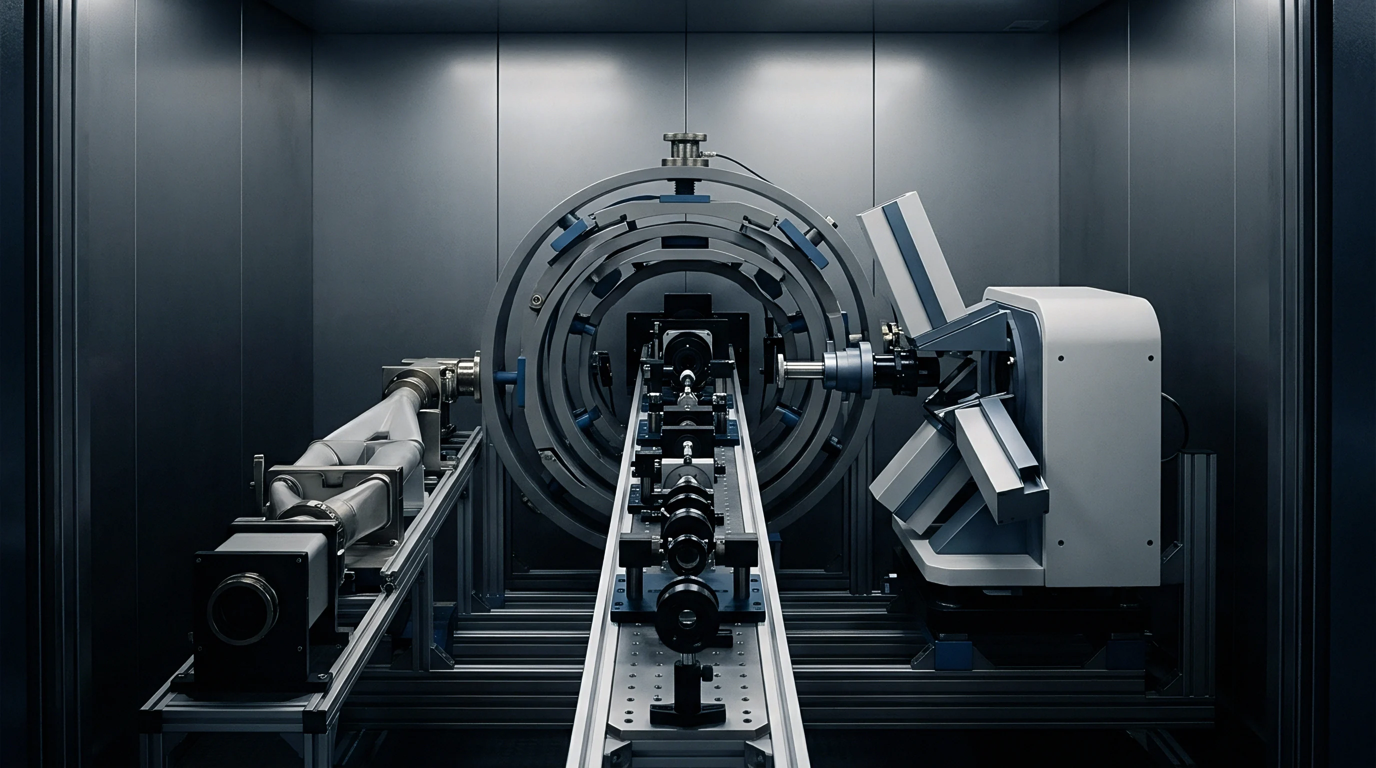
Extracting non-linear scale factor coefficients requires specialized test equipment capable of generating stable, precisely quantified motion profiles. Single-point rate calibrations cannot isolate higher-order terms. Characterization runs sweep the sensor through discrete acceleration or rate plateaus, benchmarking output against traceable metrological references.

Precision Turntable Motion Execution
Multi-axis rate tables generate stable angular velocity plateaus using direct-drive brushless motors on precision air bearings, with optical encoders resolving down to micro-arcseconds. Even so, bearing wobble and motor cogging ripple introduce spurious acceleration components that can obscure subtle transducer non-linearities. Calibration facilities counter this by mounting rate tables on seismic isolation blocks weighing tens of metric tons to filter out environmental floor vibration.
Testing relies on symmetrical stair-step rate profiles. The platform steps through ascending positive rates, pauses at zero velocity to record bias stability, and ramps down through matching negative intervals. Dwell periods at each plateau give the sensor time to settle mechanically and thermally.
Averaged samples establish steady-state output while filtering out wideband Gaussian noise, after which linear regression defines the best-fit line and separates the residual deviations needed to fit the polynomial error model.
- Chamber Environmental Stabilization stabilizes package temperature inside a sealed chamber mounted directly to the motion stage.
- Zero Rate Offset Capture records resting bias over ten minutes to establish baseline drift prior to rotation.
- Ascending Velocity Stepping steps through positive rate plateaus from ten degrees per second up to the sensor’s dynamic limit.
- Symmetrical Inversion Cycling traces identical negative rate steps to isolate directional asymmetry coefficients.
- Least Squares Polynomial Extraction fits third-order polynomials to mean plateau residuals to produce the final calibration matrices.
IEEE Std 952 establishes that gyroscope scale factor non-linearity must be evaluated as the ratio of maximum residual deviation to the full-scale output swing across specified dynamic ranges.

Will Closed Loop Force Rebalance Eliminate Higher Order Coefficients?
Closed-loop rebalancing architectures keep mechanical displacement negligible, but they shift scale factor distortion into the electronic feedback circuitry. Electrostatic force remains non-linear with respect to drive voltage. While differential drive schemes or pulse-frequency modulation help maintain constant charge delivery per pulse, finite switching rise times still bleed energy at high repetition frequencies, creating compressive scale factor non-linearity as rates rise.
Centrifuges evaluate accelerometer scale factor behavior at high specific force levels where static tilt tables fall short, producing steady centripetal acceleration exceeding one hundred gravities at extended radii. Measurement precision is constrained by arm deflection, radius uncertainties, and bearing runout. Under heavy centrifugal loading, the structural arm stretches; without dynamic interferometric tracking to adjust for the expanding radius, this elongation shows up in the data as false quadratic scale factor error.
| Calibration Equipment | Kinematic Stimulus Mode | Dynamic Span | Targeted Scale Factor Parameters | Primary Measurement Uncertainty |
|---|---|---|---|---|
| Single Axis Air Bearing Table | Continuous angular velocity | 0.01 to 3000 deg per sec | S1 primary scale, S2 asymmetry, S3 compression | Bearing wobble and optical encoder quantization |
| Dual Axis Rate Tilt System | Multi-axis angular rotation | 0.1 to 1000 deg per sec | Cross-axis scale coupling and alignment angles | Orthogonal axis gimbal misalignment |
| Precision Arm Centrifuge | Radial centripetal acceleration | 1 to 200 g | Accelerometer quadratic and cubic scale factors | Dynamic arm stretch under centrifugal loading |
| Angular Vibration Exciter | Sinusoidal angular oscillation | 10 to 2000 Hz dynamic sweep | Frequency dependent scale factor and resonance | Harmonic purity of electrodynamic drive |
| Methods note: Uncertainties evaluated in accordance with standard laboratory environmental conditions maintained at 20 degrees Celsius. | ||||
Factory single-temperature calibration may suggest sub-hundred parts per million linearity across normal operations, but raw scale factor residuals multiply by orders of magnitude once structural frame flexing and electronic rebalancing limits engage at peak operational rates.


Coupling
Scale factor non-linearity shifts continuously under operational environmental stress. Ambient temperature variations alter the physical geometry and elastic moduli of micromachined silicon structures, shifting higher-order polynomial coefficients throughout field deployment. At the same time, mechanical shock and packaging stress warp internal clearances, altering electrostatic transfer gains across the flight envelope.
Thermal Gradients in Structural Silicon
Operating temperature directly affects the Young’s modulus of single-crystal silicon, which softens as it heats, reducing mechanical suspension stiffness by approximately sixty parts per million per Kelvin. Linear scale factor drifts accordingly, while thermal expansion strains the anchor tabs. The higher-order polynomial coefficients exhibit their own distinct temperature coefficients as well.
Thermal gradients across the die induce uneven mechanical stress. Power dissipation within the application-specific integrated circuit creates localized hotspots that bleed through die-attach adhesives into the MEMS substrate. When opposing suspension beams expand unevenly, the proof mass tilts from its nominal alignment, shifting second-order scale factor asymmetry.
Passive thermal models break down whenever these gradients fluctuate during power-on transients or sudden environmental swings.
A thermal gradient of two degrees Celsius across a micromachined gyroscope die shifts second-order scale factor asymmetry by eighty parts per million.
Solder joint fatigue alters package compliance over time. Coefficient of thermal expansion mismatches between ceramic leadless chip carriers and fiberglass circuit boards generate shear stresses that propagate through the package walls and deform the internal die cavity. These stresses alter the gaps between capacitive comb fingers, disrupting electrostatic linearization and compromising scale factor accuracy at high rates.

Vibration Rectification and Stress Drift
Dynamic vibration environments drive substantial scale factor shifts via rectification. High-frequency linear vibrations outside the operating bandwidth excite sub-harmonic resonant modes in the mechanical suspension. Non-linear restoring forces then rectify these rapid oscillations into direct-current offsets, distorting the apparent scale factor.
G-squared sensitivity in gyroscopes is a direct manifestation of this coupling: linear acceleration displaces the proof mass from its plane of symmetry, making the Coriolis transfer gain dependent on the instantaneous linear acceleration vector. This cross-coupling feeds vibrational energy straight into the angular rate channels as non-linear measurement error.
- Thermo Mechanical Stress Isolation isolates the silicon die from circuit board flexure using compliant silicone gel die attaches.
- Multi Point Thermal Mapping evaluates polynomial scale factor coefficients across at least five discrete temperatures to populate vehicle compensation tables.
- Resonant Frequency Rejection suppresses high-frequency vibration through mechanical isolators tuned below the sensor’s structural resonance.
- Symmetrical Structural Design anchors suspensions centrally on the die so outward thermal expansion cancels symmetrically.
Isolating higher-order thermo-mechanical coupling from pure kinematic non-linearities during severe dynamic shocks remains difficult without real-time stress telemetry gathered directly on the die.

Procurement
Procurement specifications for inertial measurement units require precise definitions of scale factor non-linearity. Catalog accuracy claims frequently mask severe performance drops at operational limits. Without clear contractual requirements covering test conditions, dynamic ranges, and verification mathematics, suppliers deliver hardware characterized only over narrow central operating windows.

Factory Calibration Cycle Economics
Multi-point rate testing on automated motion tables accounts for a substantial share of finished sensor manufacturing costs. Characterizing a sensor at room temperature across three rate points takes under two minutes on the table. Expanding that to an eleven-point sweep across three thermal chambers pushes test time past forty-five minutes per unit, while five-point sweeps double baseline costs.
Chamber thermal settling times dictate total factory throughput.
Programs requiring tactical or navigation-grade precision face a direct trade-off between unit purchase price and downstream software complexity. Industrial-grade sensors leave the foundry with simple linear correction values burned into on-chip registers. The integrator must then decide whether to accept drift during aggressive vehicle maneuvers or absorb the expense of post-assembly characterization on multi-axis motion tables.
| Sensor Grade | Dynamic Range | Specified SFNL Limit | Factory Calibration Scheme | Relative Calibration Cost Impact |
|---|---|---|---|---|
| Industrial Automated | Plus or minus 300 deg per sec | 500 to 1200 ppm | Single temperature, three rate points | Baseline reference cost |
| Tactical Guidance | Plus or minus 1000 deg per sec | 50 to 200 ppm | Three temperatures, seven rate points | 3.5 times baseline cost |
| Precision Navigation | Plus or minus 400 deg per sec | 5 to 25 ppm | Five temperatures, eleven rate points | 8.2 times baseline cost |
| High Dynamic Flight | Plus or minus 2000 deg per sec | 100 to 300 ppm | Multi-point dynamic sweep with vibration | 12.0 times baseline cost |
Yields decline when contracts mandate tight scale factor linearity across wide dynamic spans. Foundries encounter wafer-level fallout caused by etch rate variations in deep reactive-ion etching over large substrates. Comb fingers near wafer perimeters develop subtle sidewall tapers that violate second-order asymmetry limits, forcing manufacturers to scrap otherwise functional silicon.

Specification Clauses for Non Linear Boundaries
Specifications need to bind scale factor non-linearity to verified test protocols rather than headline datasheet figures. Contracts must define the curve-fitting methodology explicitly, distinguishing between best-fit straight line and terminal-point straight line approaches. A best-fit line minimizes root-mean-square residuals across the entire range, masking pronounced non-linearities at the outer edges.
A terminal-point fit pegs error to zero at the extremes, throwing internal curvature into sharper relief.
Agreements must also establish the dynamic profile used during lot acceptance. Relying purely on static rate steps fails to uncover frequency-dependent scale factor distortions introduced by feedback delays and digital filter decimation. To protect mission performance, contracts need to define dynamic rate sweep rates, cross-axis limits, and post-vibration non-linearity retention thresholds.
Invoking IEEE Std 1293 Section 7.2 requires suppliers to deliver raw calibration residual matrices alongside computed polynomial coefficients for every serialized unit, placing the burden of characterization where it belongs ~ on the factory test floor.