Inertial Measurement Unit Multi Axis Cross Axis Calibration Standard Methods
Decouple multi-axis IMU cross-coupling by combining multi-position static tumbling with dynamic rate table sweeps to populate deterministic nine-term error matrices.
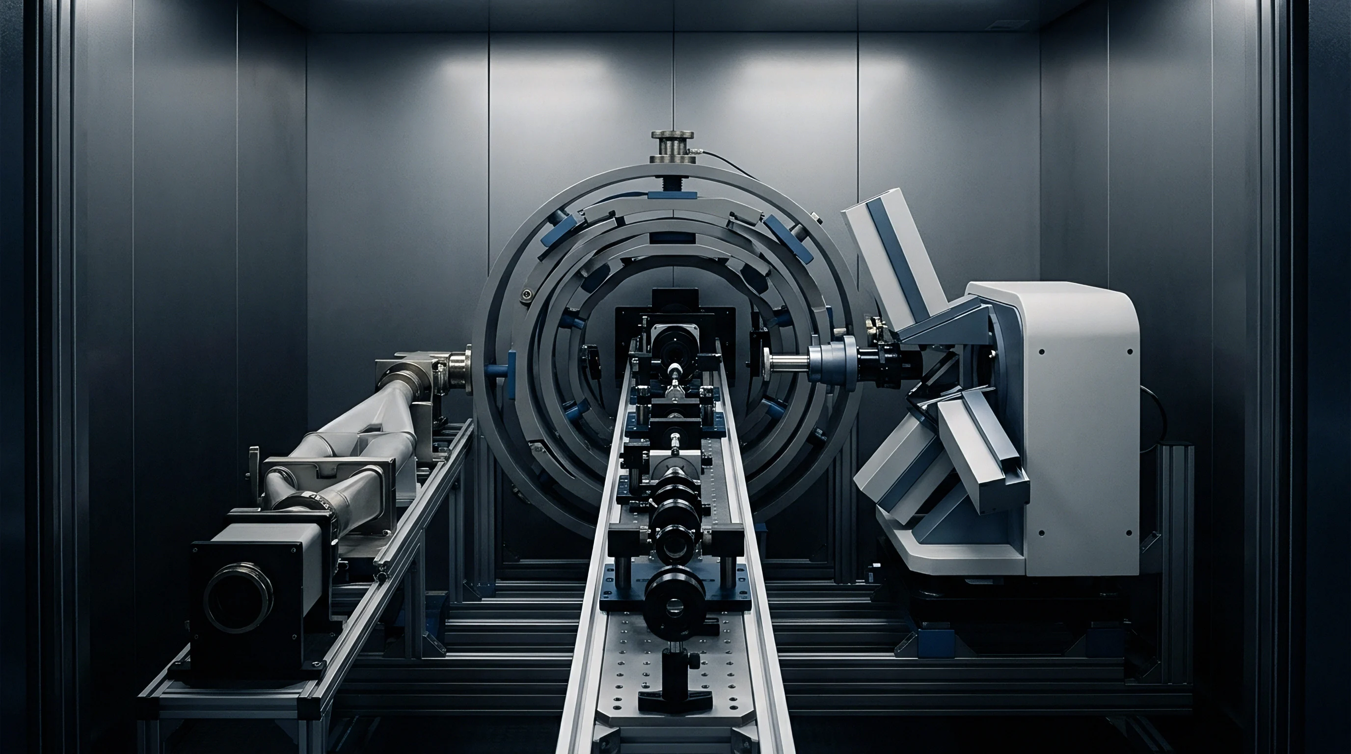

Matrix
Cross-axis sensitivity in an inertial measurement unit occurs when motion along one primary axis registers as parasitic output on orthogonal channels. It stems from mechanical misalignment during package bonding, etching asymmetries in the microelectromechanical proof mass, and capacitive or piezoresistive cross-talk in the read-out integrated circuit. Left uncorrected, angular rates bleed into lateral acceleration channels, and gravity corrupts orthogonal gyro axes during sustained turns.
Under IEEE 952 and IEEE 528, the kinematic error model treats this cross-axis relationship as a deterministic linear transform. Sensor output is modeled as the true acceleration or angular rate multiplied by a three-by-three matrix (upper triangular or full), with primary scale factors on the diagonal and cross-coupling terms off-diagonal. For an accelerometer triad measuring specific force, the observation vector links directly to true force via those systematic terms.
A triaxial assembly reading a single g along its primary sensing vector routinely couples between three and twelve milli-g into lateral axes before matrix correction.
True input acceleration maps into the sensed voltage or digital count through explicit components:
- Scale factor matrix establishes primary conversion gains alongside off-diagonal geometric cross-coupling terms spanning all three orthogonal planes.
- Bias vector accounts for zero-input DC offsets induced by package stress, thermal gradients, and analog front-end residual voltages.
- Nonlinear kinematic coefficients capture second-order rectification errors and cross-acceleration sensitivities under sustained dynamic vibration profiles.
These sensitivity coefficients shift across assembly stages. Board warpage during lead-free reflow routinely introduces skew angles above 0.5 degrees ~ a tilt that creates cross-axis errors exceeding the die’s own micromachined tolerances. That uncalibrated 0.5-degree mounting tilt permits roughly 8.7 milli-g of lateral bleed per single g of normal acceleration, where precision guidance applications tolerate less than 0.1 milli-g.

Mathematical Decoupling Formulation
Decoupling algorithms split intrinsic sensor non-orthogonality from external mounting misalignments. The overall sensitivity matrix factors into an orthogonal transformation matrix for coordinate rotation and a non-orthogonal shape matrix for internal sensor skew. IEEE 1554 outlines this separation specifically to prevent bench alignment artifacts from being baked into the operational navigation frame.
| IMU Performance Grade | Intrinsic Die Non-Orthogonality | Reflow Solder Angular Skew | Cross-Axis Coupling Range | Uncorrected Pointing Vector Error |
|---|---|---|---|---|
| Consumer MEMS | 0.20 deg to 0.60 deg | 0.30 deg to 0.80 deg | 1.0% to 3.0% full scale | 12 mrad to 25 mrad |
| Industrial MEMS | 0.05 deg to 0.15 deg | 0.10 deg to 0.25 deg | 0.1% to 0.5% full scale | 1.5 mrad to 5.0 mrad |
| Tactical Grade (FOG or Precision MEMS) | 0.01 deg to 0.03 deg | 0.02 deg to 0.05 deg | 0.01% to 0.05% full scale | 0.2 mrad to 0.8 mrad |
| Navigation Grade (RLG or Resonator) | 0.001 deg to 0.005 deg | Mechanically shimmed base | below 0.005% full scale | under 0.05 mrad |
Scale factor asymmetries compound these errors whenever positive and negative rotations produce different slopes. Calibration routines handle this by separating diagonal and off-diagonal terms into sign-dependent coefficients. In fact, IEEE 528 Clause 5.2.3 enforces the reporting of sign-dependent cross-coupling coefficients, invalidating calibration sheets that collapse positive and negative sweeps into a single averaged scalar.

Tumble
Static multi-position calibration ~ commonly called tumble testing ~ relies on Earth’s gravity as an invariant reference. Stepping a sensor through a defined sequence of orientations isolates accelerometer biases, scale factors, and cross-axis alignment angles without dynamic centrifuges. Precision dividing heads orient the sensor platform to known angles relative to the local gravity vector.
A standard six-position sequence exposes each sensitive axis sequentially to positive one g and negative one g fields. That provides six independent scalar measurements, solving six equations for three biases and three diagonal scale factors, but it leaves cross-axis off-diagonal terms unresolved because orthogonal axes sit in nominal zero-g fields without angular differentiation.
Resolving the full nine-parameter matrix requires twelve-position or polyhedral twenty-four-position profiles, where the fixture rests at 45-degree inclinations. Tilted at these angles, gravity projects simultaneously across multiple axes, exposing cross-axis non-orthogonalities directly against known gravitational vector components.
Take a representative calibration sequence on an industrial triaxial capacitive accelerometer triad. The sensor mounts inside an indexing cube on a granite surface table aligned to local gravity within two arcseconds, where local gravity equals 9.80665 meters per second squared. Nominal sensor sensitivity stands at 1000 least significant bits per g.
In an ideal cube, positive and negative vertical orientations produce plus or minus 1000 counts.
The indexing head rotates the unit through twelve discrete positions. Assume the true calibration parameters yield:
- Offset residuals measuring 12 counts on X, negative 8 counts on Y, and 24 counts on Z under zero-field conditions.
- Diagonal scale deviations generating 1004 counts per g on X, 997 counts per g on Y, and 1002 counts per g on Z.
- Cross-axis misalignment coefficients producing an X-axis output of 8 counts per g of pure Y acceleration and negative 5 counts per g of pure Z acceleration.
When the cube sits with its Y-axis pointing straight up along gravity, an ideal X channel reads zero. The actual uncalibrated sensor reads its 12-count bias plus the 8-count cross-axis leakage from the vertical Y-axis, totaling 20 counts on channel X. When inverted so the Y-axis points downward, the X channel reports 12 counts minus 8 counts, yielding 4 counts. Differencing those two opposing orientations isolates the cross-coupling term from the static bias.
Inverting an axis across gravitational directions cancels static bias while isolating cross-coupling coefficients.
Solving the full linear system uses a least-squares parameter estimator to minimize the residual norm between measured specific force magnitudes and the local gravity scalar across all test orientations. Accelerometer cross-axis matrices calibrated through 24-position polyhedral static tests reduce residual unmodeled cross-coupling to below 0.02 percent of full scale.
Earth rate tumble calibration serves a similar function for gyroscopes, using planet rotation ~ 15.041 degrees per hour at the equator ~ as the reference. Only tactical and navigation grade sensors possess noise floors low enough to extract Earth rate signals from static multi-position dwell periods; consumer units drown planet rotation beneath velocity random walk.
Clean gravitational tumbling requires meticulous table leveling, since tilt errors in the bench fixture map directly into false non-orthogonality coefficients.

Rate
Dynamic cross-axis calibration for angular rate sensors requires multi-axis rate tables equipped with continuous slip rings and absolute optical encoders. Because angular rate cannot be generated statically, dynamic validation demands applying controlled rotational velocities around one axis while acquiring data across orthogonal channels to capture centrifugal, Coriolis, and structural cross-coupling.
The protocol exercises the unit across target angular velocity limits, such as plus and minus 300 degrees per second, stepping in discrete rate plateaus. Single-axis rate tables require labor-intensive manual re-fixturing between passes, and that repeated clamping introduces mechanical mounting offsets that distort off-diagonal calibration terms. Three-axis motion simulators rotate all axes simultaneously, preserving reference coordinate integrity across the entire calibration profile.
| Standard Designation | Kinematic Stimulus | Target Sensor Parameter | Settling and Dwell Criteria |
|---|---|---|---|
| IEEE 952 Clause 6.4 | Multi-rate continuous turntable sweep | Gyro scale factor and cross-axis alignment | 10 second dwell per velocity plateau |
| IEEE 528 Clause 7.3 | Precision centrifuge rotation | Accelerometer cross-acceleration sensitivity | Thermal stabilization within 0.1 deg C |
| ISO 16063-21 | Dual-axis sinusoidal vibration | Dynamic cross-axis sensitivity ratio | Swept frequency 10 Hz to 2 kHz |
| IEEE 2923 Clause 4.2 | Simultaneous multi-axis rate tumbling | G-dependent gyro drift coefficients | Continuous trajectory loop closure |
Centrifuge testing separates linear acceleration sensitivities from rotational inputs. Spinning subjects gyroscopes to pure linear acceleration fields up to 50 g without generating angular velocity about the sensing axes. Piezoresistive and capacitive MEMS gyroscopes exhibit asymmetric proof-mass deflection under extreme g-loads, creating apparent rotation signals on stationary gyro channels.
The resulting calibration terms form the g-sensitivity matrix, expressed in degrees per hour per g.
Centrifuge testing verifies g-dependent gyro cross-talk independently of angular rate inputs.
Cross-axis rate table sweeps also expose frequency-dependent phase shifts. At low angular velocities, Coriolis signals couple into adjacent channels through purely geometric misalignment. Under high-frequency angular vibration, structural resonances in the MEMS drive frame induce parasitic quadrature signals that the ASIC demodulator leaks directly into the orthogonal rate channel.
Neglecting dynamic cross-axis terms causes severe orientation drift in flight control loops. During an aggressive roll, an uncalibrated unit computes false pitch and yaw rates; the autopilot attempts to correct nonexistent perturbations, driving flight surfaces into dangerous divergent attitudes.

Shim
Mechanical mounting interfaces represent the largest physical source of non-orthogonality. Internal die-attach adhesives exhibit non-uniform thickness variations between 5 and 20 micrometers across a four-millimeter package. During solder reflow, surface tension pulls the package out of planarity, tilting the sensing frame relative to the printed circuit board assembly.
Precision ground shims and micro-machined kinematic mounts mechanically restore true orthogonality before software calibration occurs.
Clamping a planar circuit board to an uneven chassis plate flexes the board when mounting screws torque down. This board deflection alters relative angular alignment between independent single-axis sensor packages. Monolithic nine-axis sensor dies avoid inter-package mechanical flexure because all proof masses sit on common silicon, though they trade that structural advantage for severe thermal stress coupling across internal micro-machined beams.
Differential thermal expansion between the silicon sensor die, the ceramic substrate, and the FR4 motherboard warps the package across operating temperature sweeps. The resulting strain alters both the mechanical spring constants and the geometric tilt angles of the internal capacitive fingers. Cross-axis errors calibrated at 25 degrees Celsius drift substantially when ambient temperatures rise to 85 degrees Celsius.
Calibrating cross-axis sensitivity across temperature requires integrating multi-axis rate tables inside thermal environmental chambers. Logging coupling coefficients across five-degree thermal increments allows firmware to build multidimensional polynomial interpolation tables that adjust off-diagonal decoupling terms dynamically in operational code.
Production line constraints frequently restrict calibration to room temperature.
Batch
Commercial viability hinges on total time spent on precision calibration hardware. High-grade inertial navigation systems justify six-hour multi-axis tumbling and rate table runs across multiple temperature plateaus. High-volume automotive safety sensors permit fewer than thirty seconds of bench test time per unit before assembly into electronic stability control modules, forcing statistical trade-offs during cross-axis testing.
Factory calibration routines utilize batch processing fixtures handling sixty-four devices simultaneously on a single rate table platen. Mechanical tolerances across multi-socket test fixtures introduce spatial variation: devices positioned at the outer radius of a 500-millimeter platter experience higher tangential linear velocities during rate sweeps than devices sitting near the platen center. Calibration software must subtract position-dependent centripetal acceleration vectors from each sensor channel.
Sourcing strategies depend directly on whether cross-axis calibration occurs at the component level or the integrated system level:
- Raw component screening tests individual packaged parts on automated handler turntables, rejecting die lots with intrinsic non-orthogonality exceeding 0.2 degrees.
- Post-reflow printed board calibration runs assembled board arrays through rapid three-position tumble fixtures to calibrate mounting skew before potting.
- Enclosure-level system calibration executes final matrix compensation on fully sealed devices inside their production housings to absorb mechanical installation strains.
While system-level calibration delivers superior accuracy, it demands capital expenditure on specialized multi-axis rate chambers. Production facilities balance this investment against warranty failure rates, since omitting system-level cross-axis testing transfers systemic risk down the supply chain.
Whether simplified ten-second factory tumbling routines can adequately decouple thermal stress hysteresis from true geometric cross-axis alignment across wide operating spans remains an open engineering dispute.