Inductive Proximity Replacement for Optical Sensors in Washdown Environments
Replacing optical sensors with 316L stainless inductive proximity units eliminates washdown fluid blinding and restores line uptime in CIP zones.


Rinse
High-pressure liquid cleaning in food, beverage, and pharmaceutical plants puts severe mechanical and chemical stress on automation sensors. Daily clean-in-place and clean-out-of-place routines expose equipment to hot, aggressive cleaning solutions under high pressure. In these environments, standard optical sensors ~ whether retro-reflective, diffuse-reflective, or thru-beam photoelectric ~ frequently fail or lose sensitivity, largely because light transmission breaks down under washdown conditions.
Optical sensing relies on an unobstructed air gap between optics and target, but that path rarely stays clear during washdown. Water droplets, alkaline foam, and organic films collect on lens surfaces, scattering and attenuating the beam. Cold lens covers also fog over when warm washdown water hits cool machinery, creating a film that blinds photoelectric receivers.
The sensor reads this signal drop as a target state change, triggering false stops and timing errors along the line.
The physical construction of standard optical housings further encourages moisture ingress. Procedures compliant with DIN 40050-9 and IEC 60529 IP69K blast equipment with 10 MPa (100 bar) jets at up to 80 °C from distances of 100 mm to 150 mm. Standard optical units typically pair polycarbonate or polymethyl methacrylate lens covers with thermoplastic or nickel-plated brass bodies, joined by elastomeric adhesives.
Rapid temperature swings between hot washdown cycles and cold operating conditions cause differential thermal expansion across these bonded seams, eventually cracking the seals and allowing wash solutions into internal circuits.
Aggressive sanitizers compound the damage. Standard CIP protocols run 2% to 5% sodium hydroxide solutions to strip fats, 1% to 3% nitric or phosphoric acid to dissolve scale, and peracetic acid or chlorine dioxide for final sanitization. Exposed to peracetic acid, polycarbonate lenses develop micro-cracks and surface clouding within weeks.
This permanently scatters light, dropping excess gain below reliable thresholds. As signal strength fades during repeated CIP cycles, technicians frequently adjust sensitivity potentiometers or recalibrate teach-in parameters, introducing manual error and operational drift.
Inductive proximity sensors bypass these optical vulnerabilities by detecting metallic targets through high-frequency electromagnetic fields. Because magnetic fields pass through water, foam, caustic solutions, and organic residue without signal loss, surface buildup does not blind them. A layer of opaque sanitizing foam across an inductive face causes no shift in switching thresholds, eliminating light path dependencies altogether.
Replacing optical sensors with inductive switches requires matching target geometry and composition. While optical sensors detect non-metallic items, packaging films, glass, and complex profiles at distances from 100 mm out past 10 meters, inductive units operate at shorter ranges ~ typically 1 mm to 40 mm ~ and detect metal only. Converting sensing points that track stainless steel carriers, aluminum caps, machine components, or embedded ferrous inserts delivers immediate reliability gains, provided physical mounting gaps fall within inductive operating ranges.
Auxiliary lens clearing hardware, such as air knives or mechanical wipers, adds ongoing maintenance and energy overhead. Running compressed air continuously to blow clear optical windows consumes substantial power and often fails on sticky food residues or dried chemical films. Inductive sensors remove the need for air knives and wipers entirely, eliminating compressed air demand alongside moving parts that degrade under washdown.
Switching to solid-state, fully encapsulated inductive bodies improves uptime across harsh sanitation zones.
- Optical Lens Clouding lowers light transmission as peracetic acid exposure causes micro-cracking across polymer windows.
- Thermal Expansion Mismatch fractures internal adhesive bonds under rapid hot-to-cold temperature swings.
- Fluid Refraction Errors cause false output signals when droplets gather on receiver optics.
- Moisture Ingress Infiltration shorts internal circuitry following high-pressure IP69K jet impingement.
Sensor reliability in sanitary zones depends on matching operating physics to actual washdown conditions. Where optical sensors suffer from light scattering through fluid films and chemical etching of polymer lenses, inductive switches pass magnetic flux through non-magnetic surface buildup without issue. Successful conversion requires verifying target material, sensing distance, line speed, and enclosure ratings upfront.
Which mechanical target adaptors or embedded metallic inserts allow non-metallic packaging items to trigger inductive sensing fields without disrupting production line dynamics?

Coil
Inductive proximity sensors operate on LC oscillator principles, employing a ferrite core coil positioned directly behind the sensing face to generate a localized high-frequency electromagnetic field. This oscillator radiates a sinusoidal magnetic field outward into the space in front of the sensor face, with operating frequencies typically ranging between 100 kHz and 1 MHz depending on core geometry and coil inductance. When a conductive target enters this field, the alternating magnetic flux induces circulating eddy currents within the metal.
These eddy currents draw energy directly from the electromagnetic field. Their intensity varies with the target’s electrical conductivity, magnetic permeability, surface area, and distance from the core. The induced currents create a counter-magnetic field that lowers the net inductance of the coil assembly while increasing resistive loading on the oscillator.
As field energy dissipates, the oscillator signal amplitude decreases; an internal Schmitt trigger monitors this drop and flips the digital output state once amplitude passes a calibrated threshold.
The skin effect dictates how deep the electromagnetic field penetrates the target, governing energy absorption. Skin depth represents the distance below the surface where current density drops to 1/e (roughly 37%) of its surface value, defined by target resistivity, relative magnetic permeability, and oscillator frequency through the relation:
delta = sqrt( rho / ( pi f mu_0 mu_r ) )
Here delta is skin depth in meters, rho is electrical resistivity in ohm-meters, f is oscillator frequency in hertz, mu_0 is vacuum magnetic permeability (4 pi 10^-7 H/m), and mu_r is relative magnetic permeability. Ferrous metals like FE360 carbon steel feature high relative permeability (mu_r between 300 and 1000), producing skin depths of just 5 to 10 micrometers at 500 kHz. Concentrating eddy currents near the surface generates strong resistive losses, heavily damping oscillator amplitude and providing maximum sensing range.
At an operating frequency of 500 kHz, standard 304 stainless steel exhibits a reduction factor of 0.70 relative to FE360 steel, decreasing nominal sensing distance from 10.0 mm to 7.0 mm.
Non-ferrous metals possess lower relative permeability (mu_r equal to 1.0), increasing skin depth and altering field attenuation. Austenitic AISI 304 stainless steel, widespread in food processing machinery, combines elevated electrical resistivity with unity relative permeability. Magnetic flux penetrates deeper into 304 stainless, producing lower surface current density and reduced energy loss per unit volume compared to carbon steel.
Standard inductive sensors therefore exhibit reduced sensing ranges on stainless steel, aluminum, brass, and copper, quantified by material reduction factors.
| Target Material | Material Spec | Relative Permeability | Typical Reduction Factor | Effective Range (10 mm Nominal) |
|---|---|---|---|---|
| Carbon Steel | FE 360 / AISI 1018 | 300 – 1000 | 1.00 | 10.0 mm |
| Stainless Steel | AISI 304 / 1.4301 | 1.00 – 1.05 | 0.65 – 0.75 | 6.5 – 7.5 mm |
| Stainless Steel | AISI 316L / 1.4404 | 1.00 – 1.02 | 0.60 – 0.70 | 6.0 – 7.0 mm |
| Aluminum | AlMgSi0.5 / 6061-T6 | 1.00 | 0.35 – 0.45 | 3.5 – 4.5 mm |
| Brass | CuZn39Pb3 / C36000 | 1.00 | 0.35 – 0.40 | 3.5 – 4.0 mm |
| Copper | E-Cu / C11000 | 1.00 | 0.25 – 0.35 | 2.5 – 3.5 mm |
| Data based on standard IEC 60947-5-2 target size of 1 mm thick flat plate, axial approach, 20 °C ambient temperature. | ||||
Standard single-coil sensors lose significant range on non-ferrous metals. Factor-1 inductive switches overcome this limitation using multi-coil planar arrays or dual differential magnetic circuits. By analyzing amplitude and phase shifts simultaneously, factor-1 models maintain a uniform reduction factor of 1.0 across carbon steel, stainless steel, aluminum, and brass.
Deploying factor-1 sensors on 304 stainless packaging equipment avoids range drop-off, preserving full 10 mm switching thresholds regardless of metal composition.
Internal shielding dictates how sensors embed into surrounding metal structures. Shielded (flush-mountable) sensors feature a metallic ring around the core sidewalls that forces the field forward through the front face, allowing them to mount flush in metal brackets without false triggering. Unshielded (non-flush) models omit side shielding, letting magnetic flux expand laterally.
While unshielded designs achieve longer sensing ranges for a given housing size, they demand a metal-free clearance zone around the sensor head to avoid false outputs.
Field geometry establishes minimum target dimensions and approach parameters. IEC 60947-5-2 defines a standard target as a 1 mm thick square steel plate with sides matching either the sensing face diameter or three times the nominal operating distance (Sn), whichever is greater. Targets smaller than this standard absorb less field energy, shrinking the active sensing distance.
Detecting smaller features ~ such as bolt heads or narrow conveyor tabs ~ requires applying correction factors to ensure reliable switching.
Thermal fluctuations shift LC oscillator resonance and winding resistance. Hot washdowns heat the enclosure and alter coil impedance, causing uncompensated sensing distances to drift. Washdown-rated inductive switches incorporate internal temperature compensation circuits that adjust oscillator gain across ambient bands ~ typically -25 °C to +85 °C ~ maintaining consistent trip points during rapid temperature swings.
Target thickness governs field absorption up to the skin depth threshold. Materials thinner than three skin depths allow magnetic flux to pass through without inducing full attenuation. On beverage lines running thin aluminum foil caps, using a sensor with a higher oscillator frequency keeps skin depth thinner than the foil layer.
Matching oscillator frequency, target metallurgy, and core shielding ensures crisp switching under tight physical tolerances.
Target conductivity determines available sensing distance, while internal coil shielding dictates necessary physical clearance around the sensor face.


Barrier
Mechanical construction and sealing integrity determine whether a sensor survives harsh washdown service. Housings made from nickel-plated brass or anodized aluminum degrade quickly under caustic cleaners and acid rinses. Microscopic pinholes in nickel plating admit moisture that oxidizes the underlying metal and peels the plating, while sodium hydroxide etches anodized aluminum, thinning body walls and compromising seals.
Demanding sanitary areas require enclosures built from high-grade austenitic stainless steel, specifically AISI 316L (1.4404).
AISI 316L stainless steel incorporates 16% to 18% chromium, 10% to 14% nickel, and 2% to 3% molybdenum. The addition of molybdenum improves resistance to pitting and crevice corrosion in chloride-rich environments, such as saline processing lines or chlorine washes. Carbon content kept below 0.03% prevents chromium carbide precipitation during laser welding, preserving corrosion resistance along welded joints.
Surface finish is equally critical: fine polishing below Ra 0.8 micrometers eliminates microscopic voids where bacteria harbor and chemical residues collect.
The sensing face remains the most vulnerable point on standard proximity switches. Because electromagnetic fields require a non-metallic window, typical sensors rely on polybutylene terephthalate or polyamide face caps sealed with elastomeric O-rings. High-pressure jets at 100 bar force liquids past O-ring seats, while harsh chemicals induce stress cracking in standard polymers.
Washdown-rated units employ Polyetheretherketone (PEEK) or ceramic (Al2O3 alumina) faces mechanically locked and bonded into 316L stainless steel bodies.
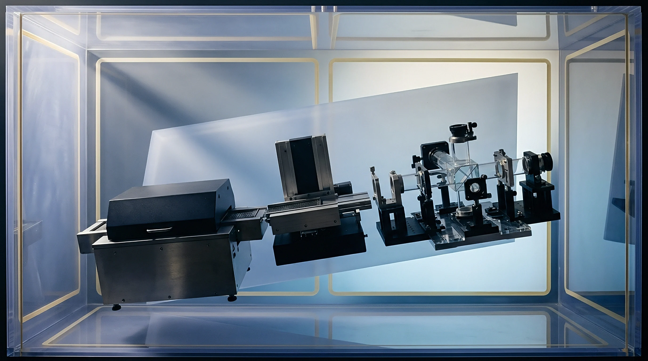
Do PEEK Sensing Faces Resist Caustic Crack Growth?
PEEK combines high mechanical strength with chemical resistance across pH 1 to 14 and continuous temperature tolerance up to 250 °C. It resists steam hydrolysis and withstands regular exposure to peracetic acid and caustic soda without softening or cracking. Ceramic faces provide extreme hardness and scratch resistance for abrasive slurry or dry bulk lines, using active metal brazing or glass-frit seals to bond hermetically with metal housings across thermal cycles.
Laser welding creates a continuous metallurgical bond between 316L stainless body components and front retainers, dispensing with threaded joints and adhesives. Precision laser seams leave zero gaps for bacterial harboring or fluid penetration. When securing PEEK face caps inside 316L housings, an interference press fit with laser-formed retaining lips seals internal cavities against severe thermal shock.
Sensors rated to DIN 40050-9 IP69K must withstand a water flow rate of 14 to 16 liters per minute at 80 °C under 10 MPa pressure at angles of 0, 30, 60, and 90 degrees without moisture penetration.
Thermal shock ingress causes frequent field failures in hollow housings. When cold water hits warm equipment during washdown, internal air contracts rapidly, generating a vacuum differential (delta P up to 0.3 bar) that pulls cleaning fluids past O-rings and cable gland seals. Encapsulating internal components in potting compound eliminates air voids completely, preventing vacuum-driven moisture ingress.
Potting formulations must combine high dielectric insulation with thermal conductivity and stress relief. Two-component polyurethanes and epoxies fill the interior space surrounding the coil, core, and circuit board. Polyurethane provides sufficient compliance to absorb differential thermal expansion between internal copper windings and the stainless steel shell, while epoxy supplies high mechanical rigidity and dielectric strength, securing internal wire bonds against machine vibration.
| Material Name | Material Class | Sodium Hydroxide (5%) | Peracetic Acid (2%) | IP69K Suitability | Failure Mechanism |
|---|---|---|---|---|---|
| AISI 316L Stainless | Austenitic Steel | Excellent | Excellent | Compliant | Chloride pitting above 60 °C |
| Nickel-Plated Brass | Plated Metal | Poor | Poor | Non-Compliant | Plating pinhole delamination |
| PEEK Resin | Thermoplastic | Excellent | Excellent | Compliant | Mechanical impact fractures |
| Polycarbonate | Thermoplastic | Poor | Unacceptable | Non-Compliant | Environmental stress cracking |
| Fluorocarbon (FKM) | Elastomer Seal | Good | Fair | Compliant | Steam hardening at high temp |
| EPDM Rubber | Elastomer Seal | Excellent | Good | Compliant | Swelling in oils and fats |
Cable entry points require robust strain relief and durable elastomeric sealing. Standard PVC cable jackets harden and split under exposure to synthetic lubricants and caustic sanitizers. Washdown-rated sensors utilize Thermoplastic Elastomer (TPE), Polyurethane (PUR), or Polypropylene (PP) jackets over braided shielding.
Cable glands incorporate molded TPE relief boots with dual O-ring compression seals, while integrated M12 connectors housed in 316L stainless shells feature gold-plated pins and FKM sealing nuts to maintain IP69K integrity under spray.
Line upgrade specifications should mandate 316L stainless steel for all mounting hardware and brackets. Standard zinc-plated hardware induces galvanic corrosion when paired with 316L sensor bodies in wet environments. Stainless mounting brackets designed with smooth, rounded surfaces eliminate chemical pooling areas and wash clean during CIP routines.
- Material Specification Audit ensures all wetted metal surfaces consist of certified AISI 316L stainless steel with surface roughness below 0.8 micrometers.
- Thermal Expansion Matching verifies potting resin flexibility absorbs differential movement between PEEK caps and metal bodies without joint failure.
- Hermetic Sealing Assessment requires laser-welded structural joints rather than mechanical thread-and-adhesive assemblies across critical boundaries.
- Cable Jacket Compatibility matches TPE or PUR cable materials against facility chemical exposure lists to prevent outer sheath cracking.
Inadequate enclosure materials and unsealed joints lead directly to fluid ingress, signal corruption, and premature sensor failure during sanitation. Specifying laser-welded 316L stainless steel housings with PEEK or ceramic faces protects internal electronics through years of aggressive CIP routines, avoiding line downtime and continuous replacement cycles.
Timing
Converting from optical to inductive sensing requires evaluating signal response limits. Photoelectric sensors achieve high switching frequencies, often 1 kHz to 5 kHz, with response times below 100 microseconds due to rapid photodiode response and optical speed. Inductive switches rely on LC oscillator decay dynamics, yielding lower maximum switching rates ~ typically 100 Hz to 2 kHz depending on coil geometry and inductance.
Switching frequency defines the maximum number of damped-to-undamped oscillator transitions a sensor handles per second. Under IEC 60947-5-2, this is measured using a rotating target wheel with a 1:2 mark-to-space ratio. As metal segments pass the face, the oscillator requires a finite number of AC cycles to collapse amplitude on target arrival and rebuild field energy upon departure.
Higher internal operating frequencies allow smaller coil designs and faster response, though reduced coil size shrinks maximum sensing distance.
Line velocity dictates target dwell time within the electromagnetic field. Calculated from target length, face diameter, approach vector, and conveyor speed, target dwell time should exceed the sensor’s combined turn-on and turn-off response time by at least two to one. On high-speed beverage or packaging lines running at 10 meters per second, a small target may traverse the sensing field in under 0.5 milliseconds, approaching the response limits of standard inductive processing circuits.
Consider a canning line operating at 1,200 cans per minute (20 cans per second). Container centers are spaced 75 mm apart with a 65 mm body diameter, leaving a 10 mm gap between cans at a line speed of 1.5 meters per second. A 12 mm diameter inductive sensor with a 4 mm nominal range forms a detection envelope roughly 15 mm wide along the path.
Each container edge dwells in this field for approximately 10 milliseconds, separated by a 6.6 millisecond gap window. A sensor rated for a 500 Hz switching frequency operates on a 2 millisecond cycle time, providing ample speed to count and position every container accurately.
Inductive sensor switching frequency must exceed twice the maximum target passing rate to satisfy Nyquist sampling requirements across high-speed packaging lines.
Output stage response adds further propagation lag in fast motion systems. Internal NPN, PNP, or MOSFET switching transistors exhibit turn-on delay (ton) and turn-off delay (toff) ranging from 10 microseconds to 500 microseconds. When connected to high-speed PLC counter cards, total signal latency reflects sensor response, field wiring capacitance, and PLC input filtering constants.
While optical devices generate sharp edge transitions, inductive sensors introduce small, deterministic delays that must be compensated in motion controller timing routines.
- Calculate maximum target line velocity in meters per second and determine minimum physical target length passing the sensor face.
- Compute target dwell time within the sensor’s effective sensing envelope based on sensor diameter and operating distance.
- Select an inductive sensor whose specified switching frequency provides a total response time less than half the calculated target dwell time.
- Adjust PLC input filter constants to match sensor output pulse width while filtering out electromagnetic noise.
- Verify target registration accuracy at full production speed using an oscilloscope connected to the sensor output line.
Oscillator field dynamics produce slight asymmetry between turn-on and turn-off detection points. As a metal target approaches, field damping lowers amplitude until it crosses the internal switching threshold. As the target retreats, field energy recovers, but Schmitt trigger hysteresis requires the target to clear a slightly greater distance before resetting the output.
This hysteresis ~ typically 1% to 15% of actual sensing distance ~ prevents output chatter from machine vibration, though it shifts the physical release point relative to activation.
Timing problems frequently appear when replacing optical sensors on high-speed equipment without verifying target dwell windows. Standard inductive switches can miss narrow targets on fast-indexing star wheels if pulse durations drop below oscillator response limits. Calculating target geometry against sensor bandwidth during engineering design prevents missed triggers during full-speed production runs.

Qualification
Comprehensive laboratory qualification should precede deployment into washdown environments. Accepting vendor datasheet claims without internal verification risks field failures. Thorough sensor qualification combines environmental stress screening, high-pressure ingress testing, and electromagnetic compatibility evaluation under controlled conditions.
IP69K compliance testing strictly follows DIN 40050-9 and IEC 60529 protocols. Test samples mount to a fixture rotating at 5 +/- 1 rpm while a standard fan jet nozzle supplies 80 +/- 5 °C water at 10 MPa (100 bar) with flow rates of 14 to 16 liters per minute. Placed 100 mm to 150 mm from the sensor face, the spray directs high-pressure water at angles of 0, 30, 60, and 90 degrees for 30 seconds per position.
Immediately following high-temperature jetting, the sensor is plunged into 20 °C water to induce thermal shock and induce internal vacuum pulling.
Post-test evaluation measures insulation resistance and dielectric isolation. A hipot test applies 500 V DC between supply conductors and the 316L stainless housing for 60 seconds, requiring insulation resistance to exceed 100 megohms. Any lower reading indicates fluid ingress across welded seams, face seals, or cable glands.
Output state monitoring during thermal cycling confirms oscillator stability without false switching.
Under IEC 61000-4-4 fast transient testing, washdown inductive sensors must withstand 2 kV burst spikes on supply and signal lines without output state disruption.
Chemical immersion protocols evaluate resistance to facility cleaning agents. Sensor samples are submerged in 5% sodium hydroxide at 70 °C for 48 hours, 3% nitric acid at 60 °C for 48 hours, and 2% peracetic acid at 20 °C for 100 hours. Following immersion, welded joints and PEEK face caps undergo 40x magnification inspection for micro-cracking, pitting, or chemical etching, alongside dimensional checks to confirm cable glands and connector seals have not swollen.
EMC qualification verifies immunity against electrical interference from VFDs, switching power supplies, and facility wireless networks. Radiated RF field immunity is tested per IEC 61000-4-3 at 10 V/m field strengths across 80 MHz to 6 GHz. Electrical fast transient (EFT) burst testing under IEC 61000-4-4 injects +/- 2 kV noise spikes into power and signal lines to simulate inductive load switching.
Washdown-rated sensors utilize multi-stage internal LC filters and metallic shielding to maintain output stability under high electrical noise.
Vibration and mechanical shock resistance are qualified under IEC 60068-2-6 and IEC 60068-2-27 standards. Sinusoidal vibration sweeps from 10 Hz to 55 Hz at 1 mm amplitude, followed by peak accelerations of 30 g (294 m/s^2) for 2 hours along each of three orthogonal axes. Shock testing exposes hardware to half-sine pulses of 50 g (490 m/s^2) for 11 milliseconds.
Qualified devices must show zero internal component displacement, seal cracking, or signal chatter throughout testing.
In accordance with IEC 60947-5-2 Clause 8.5.2, washdown inductive switches must maintain effective sensing distances within +/- 10% of nominal rating across the ambient temperature operating band from -25 °C to +70 °C.
- IP69K Verification Dossier requires certified laboratory test reports confirming zero water ingress under 100-bar spray at 80 °C.
- Chemical Exposure Log documents material mass changes and surface magnification scans following 100-hour immersion cycles.
- EMC Immunity Test Results certify zero output chattering under 10 V/m radiated RF fields and 2 kV fast transient line bursts.
- Thermal Shock Protocol Results validate insulation resistance exceeding 100 megohms after rapid 80 °C to 4 °C liquid transitions.
Pre-deployment laboratory testing mitigates integration risks before hardware reaches the factory floor. Skipping rigorous qualification exposes production lines to premature chemical degradation and noise-induced false trips. Formal testing confirms physical, electrical, and thermal robustness under real-world washdown stress.

Ledger
Evaluating sensor economics requires comparing initial purchase price with long-term lifecycle costs. Standard optical sensors carry low upfront prices ~ typically $30 to $80 each ~ but generate substantial recurring costs in washdown zones through frequent replacement, nuisance downtime, and maintenance labor. Upgrading to washdown-rated 316L stainless steel inductive switches increases hardware unit cost to $120 ~ $250, but yields substantial net savings by removing primary root causes of failure.
Total cost of ownership is driven predominantly by unplanned downtime. High-speed packaging and bottling operations incur downtime costs ranging from $1,000 to $10,000 per hour. An optical sensor failing monthly from window clouding or moisture ingress causes 30 to 60 minutes of lost production per incident when factoring in diagnostics, replacement, and recalibration.
Over twelve months, these repeated outages vastly exceed the initial cost premium of heavy-duty inductive hardware.
Service life metrics further support the investment case. Standard optical units in washdown environments average a mean time between failures (MTBF) of 3 to 6 months due to chemical degradation and thermal stress. By contrast, hermetically sealed 316L stainless inductive sensors with PEEK face caps exhibit MTBF figures exceeding 5 to 10 years under identical operating conditions.
Standardized M12 and M18 inductive housings are also widely stocked across global automation distribution channels.
| Sensor Modality & Construction | Unit Cost Range (USD) | Average Washdown Life | Annual Maintenance Hours | Relative Downtime Risk |
|---|---|---|---|---|
| Standard Optical (Polycarbonate) | $30 – $80 | 2 – 6 months | 12.5 hours | High |
| Washdown Optical (IP69K Glass Lens) | $150 – $350 | 12 – 24 months | 4.0 hours | Medium |
| Standard Inductive (Brass/PBT) | $25 – $60 | 6 – 12 months | 8.0 hours | Medium |
| Washdown Inductive (316L/PEEK) | $120 – $250 | 60 – 120 months | 0.5 hours | Low |
Standardizing mechanical footprints simplifies spare parts inventory and mitigates supply chain risk. Inductive switches follow standard M8, M12, M18, and M30 threaded cylindrical bodies or 40×40 mm block housings defined in IEC 60947-5-2. Optical sensors often employ proprietary enclosures and specialized mounting brackets that complicate cross-sourcing.
Standardizing on M12 or M18 inductive form factors enables procurement teams to source drop-in equivalents across multiple suppliers, eliminating single-source vulnerability.
Procurement specifications for washdown sensors should enforce material verification alongside electrical parameters. Requests for Quotation (RFQs) should mandate EN 10204 Type 3.1 material test certificates for all wetted metal parts to verify 316L stainless steel composition, alongside FDA compliance documentation for wetted polymers like PEEK and ECOLAB certificates for cleaning chemical resistance. Establishing strict material standards during contracting prevents substitution of lower-grade alloys or polymers that degrade under sanitation routines.
Labor savings accelerate payback timelines. Optical sensors demand recurring lens cleaning, alignment checks, and sensitivity adjustments following sanitation routines. Plant logs frequently document technicians spending up to 15 minutes per optical sensor each week wiping lenses and retuning gain thresholds.
Solid-state inductive sensors require no manual optics maintenance or gain adjustment, reallocating maintenance labor toward preventative tasks while lowering operational overhead.
Upgrading critical packaging lines to washdown inductive sensors yields typical capital payback periods under three to six months. Combining physical durability, standardized mechanical mounting, multi-vendor interchangeability, and maintenance-free operation, 316L stainless steel inductive switches represent the benchmark for reliable automation in sanitary processing areas.