Geometric Arrangement
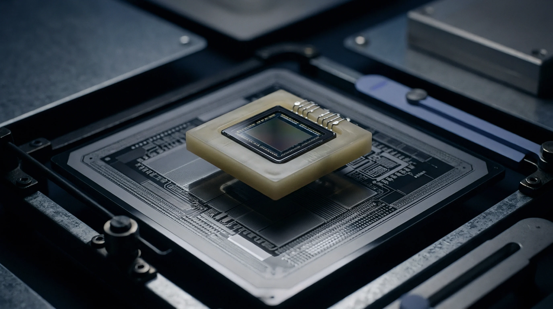
The defined vector describes the direction of the atomic planes and paths within a standard semiconductor wafer relative to the flat top surface. In fabrication steps, silicon crystallographic orientation determines the specific direction of chemical etching and the behavior of internal electrical charges in the circuit. This alignment identifies where standard 100 or 111 planes sit to ensure that every device formed in the batch has identical mechanical properties.
The consistency stops at the wafer edge or where lattice defects break the symmetry of the repeating unit structure inside the block. It measures the angle against a certified reference flat where X ray diffraction identifies the exact alignment of the silicon nuclei. Formal data records show that precise alignment stays within few tenths of a degree to maintain uniform process results.
Directional Property
Chemical behavior during wet etching depends entirely on which atomic layers face the active solution in the processing tank at any given time. When leveraging silicon crystallographic orientation, manufacturers can produce perfectly vertical side walls or steep forty five degree slopes for optical mirror mounts. This shift in geometric response allows for high volume production of miniature items with shapes that hold extremely tight dimensional tolerances.
Drift in the alignment angle leads to uneven etching where features on one side of a chip appear larger than items on the other. Calibration of the automated saw ensures that every subsequent cut follows the same high priority vector in the original ingot. Precision improves when the substrate alignment uses precision notch filters to guide robots into the correct loading position every time.
Process Influence
Mechanical and electrical coefficients change in strength as sensors are rotated relative to the defined primary axes of the base crystal. While observing the impact of silicon crystallographic orientation, testers identify the spots where transverse sensitivity is highest to maximize signal output from pressure bridges. Measuring accuracy from precision bridges depends on placing the resistors exactly on the sites with maximum piezoresistive gain constants.
Specification at reference conditions marks the zero alignment point against which angular tolerances are judged for every wafer lot. If interference from thermal warp occurs, the geometry of the crystal lattice itself stays steady even though the shape of the surface deviates slightly. Tolerance settings for crystal tilt are verified at the initial procurement stage using laser diffraction patterns.
Structural Assessment
Quality controls ensure that identical device physics occurs across separate production cycles and different facility locations globally. When evaluating silicon crystallographic orientation, teams check the split between 100 and 110 directions to confirm isolation logic for high isolation transistors works. The measurement it attests provides the boundary where etching selectivity remains functional for micro machined structures in sensors.
Beyond the tolerance limit of a few degrees, the device sensitivity may diverge from theoretical models which causes unacceptable performance shifts. Final verification involves checking the consistency of side wall profiles across dummy wafers before the main silicon production batch begins. Accurate alignment at the lattice level leads to repeatable results for millions of independent microsystems over time.
Final results show stable electrical behaviors.