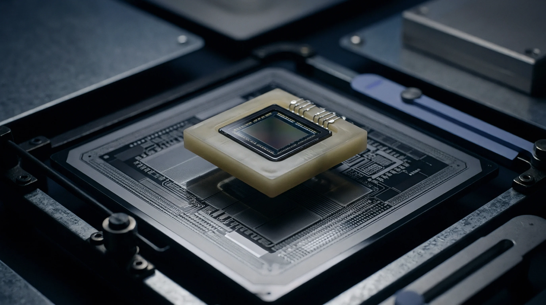
Pad Attachment
Thermal and mechanical stresses concentrate within the large central solder joint of quad flat no-lead packages during board cooling and mechanical flexure. Evaluating QFN exposed pad strain requires monitoring baseline drift in integrated sensors caused by solder joint contraction forces. The large surface area of the center thermal pad creates a rigid mechanical anchor that transfers circuit board bending straight into the silicon die.
Voiding within the center solder layer creates uneven stress distributions, increasing local strain concentrations on the package substrate. Assembly processes optimize solder paste stencils to balance heat transfer against mechanical stress generation.
Solder Voiding
Air and gas bubbles trapped in the large exposed pad solder joint alter local mechanical compliance. Large voids produce localized stress concentrations on the silicon die directly above the void boundaries. Perimeter voiding degrades thermal conductivity while central voiding creates asymmetric mechanical stress fields.
Stencil designs segment large exposed pad openings into grid patterns to facilitate gas escaping during reflow heating.
Thermal Dissipation
The large metallic center pad provides a low thermal resistance path from the silicon chip to the circuit board copper planes. Rapid heat transfer keeps junction temperatures low but subjects the central solder interface to severe thermal cycling stress. Mismatched thermal expansion coefficients between silicon, copper, and epoxy compound drive cyclic strain accumulation.
Thermal management designs must account for resultant mechanical strain to preserve long-term solder joint fatigue resistance.
Mechanical Stress
Bending moments applied to printed circuit assemblies translate into horizontal shear and vertical tensile stress on quad flat no-lead pads. Die-attached sensor arrays experience zero-point shifts under uneven pad stress due to piezoresistive effects in silicon substrates. Structural support layout rules prohibit placing critical QFN packages near high-flexure board locations like board mounting holes.
Mechanical verification protocols enforce maximum strain limits during factory depaneling and housing assembly processes.