Selecting Active Pull up Buffers for High Capacitance Sensor Buses
Active pull-up buffers restore slew rates on high-capacitance sensor lines without raising low-level output voltages or violating static sink limits.
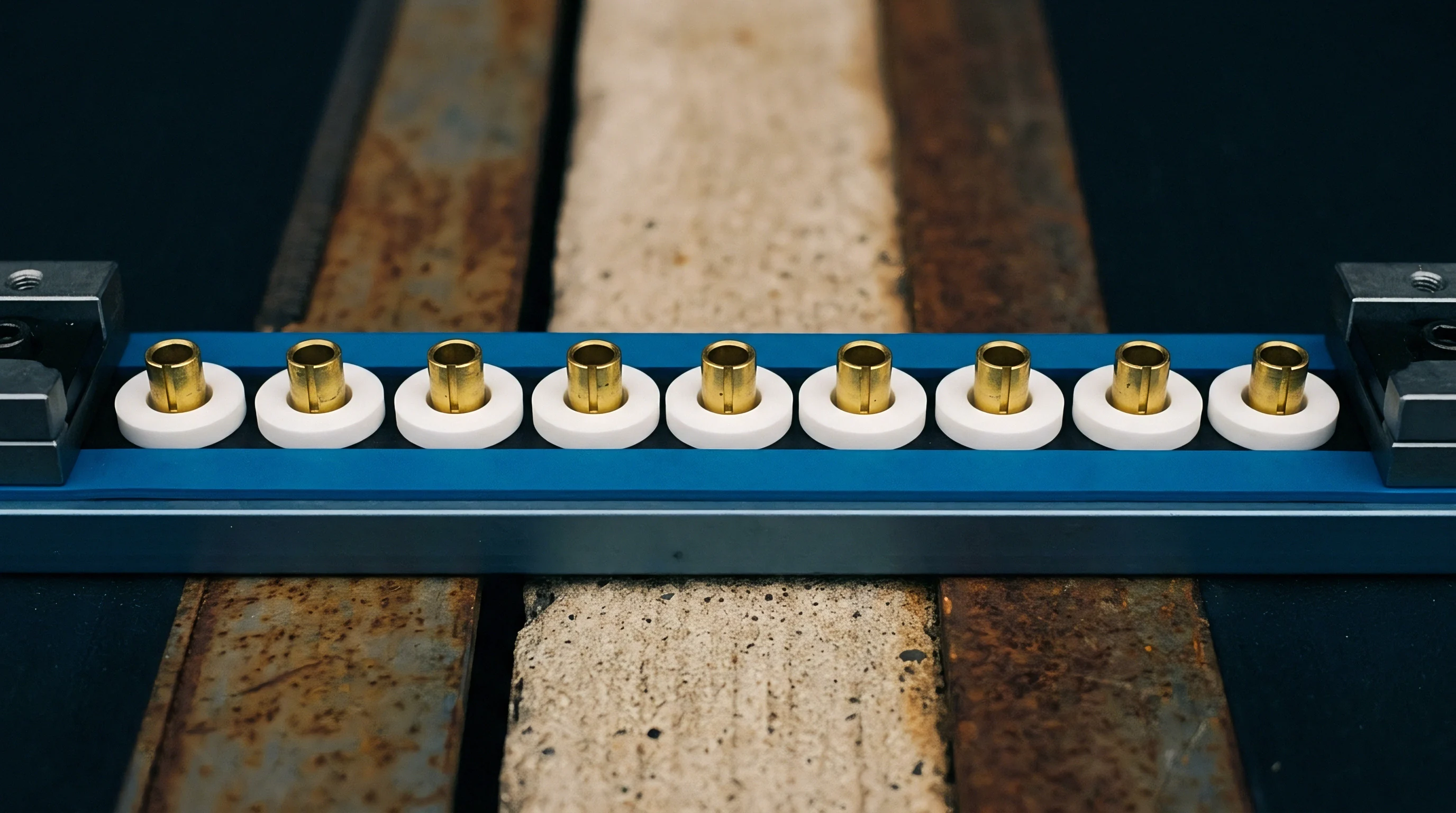

Transition
Bus capacitance past four hundred picofarads degrades open-drain clock and data lines into slow, exponential charging slopes. The standard open-drain physical layer relies entirely on passive pull-up resistors to charge trace, cable, and component pin capacitance toward the positive rail. When environmental sensor arrays, cabled temperature clusters, or backplane card cages extend aggregate line capacitance past the nominal limits defined in the UM10204 specification, sizing passive resistors down to meet the rise time ceiling creates an immediate conflict with low-level output voltage tolerances.
Sinking twenty milliamperes through a low-side field-effect transistor elevates line low-state voltage above the input low threshold of sensitive receiver nodes. Active pull-up circuitry resolves this charging bottleneck by injecting switched current pulses during rising edges without loading the bus during static high or low states.
Standard passive pull-up sizing encounters severe electrical limits on distributed branches. Equation-driven resistor calculation demonstrates that pulling a six hundred picofarad line from ground to seventy percent of a three-point-three volt rail within the three hundred nanosecond window permitted by fast-mode operation demands an effective resistance below two hundred twenty ohms. A driver pulling down against two hundred twenty ohms absorbs fifteen milliamperes of continuous current, exceeding the four-milliampere rating of standard miniature environmental sensor dies.
Package thermal dissipation climbs while the driver output low voltage shifts from two hundred millivolts to nearly seven hundred millivolts, narrowing noise margins until transient industrial noise triggers phantom acknowledge faults.
Active pull-up accelerators engage current boosters only during positive voltage transitions, disengaging completely once the line crosses the logical switching threshold.
Active pull-up buffers, termed rise-time accelerators or bus splitters, decouple charging current from static sink limits. Integrated circuits such as the LTC4311, PCA9517A, and TCA9617B monitor line voltage derivatives through internal comparators. When the sensed edge crosses an initial activation threshold, typically between zero-point-two and zero-point-five volts, internal current sources switch onto the line to pump between two and ten milliamperes of slew current into the bus capacitance.
The slew pulse forces a rapid linear ramp in place of an exponential RC tail. Once bus potential approaches within two hundred millivolts of the supply rail, the boost circuit disconnects smoothly, allowing small external resistors to establish the final static quiescent high level.
| Buffer Architecture | Dynamic Boost Current | Static Power Draw | Bus Drive Capability | Propagation Delay |
|---|---|---|---|---|
| Passive Strong Pull-Up | 0 mA | 49.5 mW | 150 pF | 0 ns |
| Single-Point Accelerator | 12 mA | 0.08 mW | 1200 pF | 0 ns |
| Bi-Directional Level Buffer | 2 mA | 5.6 mW | 400 pF per side | 110 ns |
| Optically Isolated Repeater | 0 mA | 38.0 mW | 800 pF per side | 180 ns |
Accelerator circuits function without introducing software latency or protocol alterations. The physical devices monitor voltage slope directly through analog feedback loops, responding to edges within twelve nanoseconds. Clock stretching remains fully supported because slave transceivers pull the clock line low against only the high-impedance state of the booster.
Bus masters detect no difference in transaction timing beyond cleanly squared pulses that pass formal eye-diagram masks on long industrial cable runs.
Integrating these active components preserves timing budgets across harness transitions without demanding specialized physical-layer protocols.

Clamp
High-capacitance lines routed outside a shielded card cage invite electrostatic discharge transients and severe inductive ringing. Accelerators with high-speed slew-rate transistors switch thirty to forty volts per microsecond onto sensitive traces. Rapid transitions interact with harness stray inductances, creating high-frequency ringing that can trigger parasitic input structures on miniature sensor packages.
DFN and wafer-level chip scale packages lack substantial internal silicon protection diodes, leaving thin dielectric gates vulnerable to punch-through failure when an undamped accelerator slams into the upper rail.
Diode selection demands matched clamping voltages that sit strictly below package breakdown ratings. Low-capacitance transient voltage suppressors located at the cable entry port clamp negative undershoot to negative zero-point-seven volts and positive spikes to five-point-five volts on three-point-three volt logic rails. Clamping diodes must feature parasitic junction capacitances below five picofarads; otherwise, the protection network consumes the entire capacitive headroom that the active buffer intended to recover.
Section 6.1 of the JEDEC JESD22-A114 electrostatic discharge specification establishes four-kilovolt human body model survivability boundaries that unbuffered wafer-level packages fail without external suppression.
Board layouts frequently suffer from parasitic failures arising from uncoordinated layout geometry and poor component placement:
- Inductive overshoot generates voltage spikes exceeding thirty percent of rail voltage when accelerator current sources turn off abruptly against long connector lead inductances.
- Ground bounce shifts the perceived low-state reference plane by upwards of four hundred millivolts during simultaneous line switching on unshielded flex circuits.
- Parasitic latch-up occurs within unbuffered complementary metal-oxide semiconductor dies when negative ringing pulls pins below substrate ground by more than zero-point-three volts.
- Crosstalk injection transfers steep clock edges onto adjacent high-impedance data lines across ribbon cable runs exceeding sixty centimeters.
Routing active pull-up networks calls for dedicated trace discipline. Placing bypass capacitors of zero-point-one microfarads immediately adjacent to buffer supply pins dampens high-frequency current loops during booster activation. Series damping resistors valued between ten and thirty-three ohms, placed directly in line with accelerator output pins, round off the abrupt corners of the boost pulse, preserving signal clarity while suppressing harmonic emissions across long wiring looms.
Place termination elements closest to the physical harness receptacle.


Partition
Dividing a heavy sensory bus into discrete capacitive zones prevents localized wiring faults from halting the entire operational array. Bus partition ICs use dual bi-directional channels that isolate the capacitance of daughtercard segments from backplane trunks. An input side driving three hundred picofarads connects through back-to-back pass elements to an output side handling another four hundred picofarads.
The host controller encounters only the local board load, maintaining crisp seventy-nanosecond fall times and ninety-nanosecond rise times even when forty nodes inhabit the remote branches.

Does Bus Segmentation Eliminate Address Clashes?
Downstream segmentation hardware frequently pairs capacitive partitioning with multiplexing logic. Translating signals across different voltage domains occurs simultaneously. Translating an environmental sensor core running at one-point-two volts to an industrial sensor bus operating at three-point-three volts demands level-shifting bi-directional buffers with internal offset voltages.
Devices like the PCA9517 use a built-in static voltage offset of approximately zero-point-five volts on one port to prevent signal latching. When port A drives low, port B pulls down to zero-point-five-two volts; when port B drives below zero-point-four volts, port A pulls to near ground.
| Segment Boundary | Segment Load | Buffer Class | Turn-On Delay | Turn-Off Delay |
|---|---|---|---|---|
| Host Master Trunk | 65 pF | Native Open-Drain | 0 ns | 0 ns |
| Bay 1 Sensor Hub | 380 pF | Offset Level Shifter | 45 ns | 120 ns |
| Bay 2 Sensor Hub | 520 pF | Active Rise Buffer | 18 ns | 35 ns |
| Chassis Harness Probe | 840 pF | Galvanic Optocoupler | 140 ns | 210 ns |
Engineers evaluate system delays through a disciplined sequence of bring-up tests:
- Measure total quiescent trace and connector capacitance across every unpowered branch using an LCR meter at one hundred kilohertz.
- Install primary bus repeaters at the physical midpoint of the cable assembly rather than clustering buffers exclusively at the microcontroller escape routing.
- Program the host microcontroller to output a continuous clock sequence at forty kilohertz while verifying that low-level voltages stay below zero-point-three times the local supply rail.
- Inspect edge rise rates with an active differential probe to verify that accelerator activation slopes stay uniform across all temperature ranges.
- Step bus operating frequency incrementally toward four hundred kilohertz while monitoring cyclic redundancy check error flags inside the host communication peripheral.
Timing issues emerge when series propagation delays accumulate across chained buffers. Three repeater stages in series introduce nearly four hundred nanoseconds of cumulative round-trip delay. The host clock synchronization logic perceives this propagation delay as clock stretching, which drops effective data throughput from four hundred kilobits down to one hundred eighty kilobits per second.
Total bus capacitance equals the linear sum of trace geometry, cable dielectric rating, connector contacts, and component pin loadings.
Cascading buffer offsets beyond two successive nodes causes output low levels to climb above the legal input low threshold of standard digital sensors, causing dropped transactions and bus lockups.


Inspection
Verification protocols on populated production boards require electrical and thermal screening tailored to high-density packaging. Miniature buffers ship in DFN-6, SC-70, and tiny UTQFN packages occupying less than four square millimeters. Solder inspection on bottom-terminated components demands high-resolution automated X-ray inspection to detect voiding beneath the central exposed thermal pad.
Excessive voiding degrades package thermal dissipation, elevating junction temperature when dynamic accelerators trigger repeatedly on busy data streams.

Will Solder Bridging Skew Bus Timing?
Misaligned stencils deposit solder paste that bridges high-impedance enable pins to ground, permanently disabling rise-time boost current without displaying obvious open-circuit symptoms. Automated optical inspection verifies fillet heights on leaded packages like SOT-23 and MSOP-8, but fails to assess the integrity of hidden pads beneath leadless packages. Pin-to-pin leakage currents as low as two microamperes across flux residues alter comparator trip points inside accelerators, delaying boost activation until the bus voltage drifts past the threshold organically through external pull-up resistors.
IPC-A-610 Class 3 standards dictate that bottom-terminated component solder voids remain under twenty-five percent of the total pad surface area.
Package thermal behavior under sustained bus switching warrants careful monitoring on the factory test line:
- Heated junctions increase internal pull-up switch resistance, lowering boost injection current by as much as eighteen percent at eighty-five degrees Celsius.
- Flux entrapped under leadless packages creates moisture-sensitive parasitic leakage paths that shift analog comparator reference voltages over life cycles.
- Exposed pad voids generate hot spots that alter the propagation delay of bi-directional buffers across continuous multi-byte block reads.
- Solder wicking up connector pins reduces effective mating contact area, generating localized contact resistance that introduces signal step reflections.
Contract manufacturing facilities often dismiss edge-glitch anomalies as harmless ringing caused by oscilloscope ground leads rather than acknowledging incomplete solder wetting under thin leadless land patterns.

Sourcing
Evaluating commercial silicon formats reveals extreme price and availability variance across package footprints housing identical die designs. Sourcing the same silicon geometry in a legacy SOIC-8 or MSOP-8 configuration carries a significant cost premium over modern WLCSP and DFN footprints due to leadframe stamping, molding compound volume, and older assembly line allocations. Automotive-qualified parts designated under AEC-Q100 Grade 1 command fifty to eighty percent price premiums over commercial catalog equivalents, reflecting burn-in cycles and extended cold-temperature screening.
Supply chain resilience dictates that PCB designs accommodate dual footprints wherever board layout real estate permits. Routing a primary DFN-6 land pattern inside an outer MSOP-8 footprint allows purchasing teams to alternate between reel-tape formats without redesigning circuit layers when distributor stock vanishes during global allocation cycles. Lead times for specialized rise-time accelerators routinely swing from sixteen weeks to fifty-two weeks during market crunches, penalizing single-sourced single-footprint architectures.
| Package Type | Unit Price (USD) | Board Area | Tape Pitch | Factory Lead Time |
|---|---|---|---|---|
| DFN-6 (2.0 x 2.0 mm) | $0.38 | 4.00 mm² | 4 mm | 18 Weeks |
| SC-70-6 (1.25 x 2.0 mm) | $0.42 | 2.50 mm² | 4 mm | 22 Weeks |
| MSOP-8 (3.0 x 3.0 mm) | $0.61 | 9.00 mm² | 8 mm | 36 Weeks |
| WLCSP-6 (0.8 x 1.2 mm) | $0.31 | 0.96 mm² | 4 mm | 28 Weeks |
Firmware integration complexity scales proportionally with the buffer architecture selected. Passive accelerators involve zero software intervention, requiring no register configuration, initialization routines, or driver maintenance across operating system kernel updates. Partitioning switches and programmable multiplexers introduce software overhead, requiring robust exception handling to reset frozen I2C state machines when an unplugged sensor cable stalls the bus halfway through an active transaction.
Volume pricing mechanics break down sharply on small production runs. Purchasing unprogrammed bi-directional buffers in minimum order quantities below five thousand pieces pushes per-unit costs past one dollar and twenty cents, shifting make-versus-buy trade-offs toward passive pull-up redesigns running at relaxed bus frequencies. When volume crosses one hundred thousand units, the thirty-cent cost of an accelerator chip is easily offset by the raw bill-of-materials savings realized from using thinner, unshielded four-conductor sensor wiring harnesses across wide machine assemblies.
Commercial purchase agreements stipulate that replacement silicon batches must deliver identical slew-rate activation thresholds across all qualified temperature envelopes to prevent field failures.