Diffusion Barrier Underplate Specifications for Extended Component Bake Cycles
A minimum 2.54 micrometer sulfamate or amorphous electroless nickel underplate prevents copper outdiffusion and solderability loss during extended bakes.


Strata
Selecting an appropriate plating deposit requires balancing crystal orientation against deposition stress. In component leadframe manufacturing, copper substrate alloys such as C19400 or C70250 provide high electrical conductivity but suffer from rapid atomic migration when elevated temperatures are sustained. Without a protective intermediate layer, copper atoms migrate toward the surface tin or gold finish, forming brittle intermetallic phases and oxidized surface films.
Nickel underplating serves as the structural barrier against this migration during extended thermal exposure.
Plating processes yield distinct grain structures that dictate barrier performance. Electroplated nickel deposited from a Watts bath produces a columnar microstructure. Columnar boundaries create fast-path diffusion channels along vertical grain edges, allowing substrate copper to reach the surface layer at accelerated rates.
Electroplated sulfamate nickel offers lower internal stress and finer equiaxed grains, which lengthens the path copper atoms must traverse. Electroless nickel-phosphorus deposits, by contrast, yield an amorphous or microcrystalline structure without traditional grain boundaries when phosphorus concentration exceeds eight weight percent. Nickel blocks copper movement.
Amorphous structures eliminate the primary diffusion pathways entirely.

Barrier Layer Chemistry and Microstructure
Depositing a nickel barrier layer involves controlled bath chemistry to govern grain refinement and impurity inclusion. Electroplated sulfamate solutions operating at forty-five degrees Celsius with a pH of four point zero yield deposits with low tensile stress, typically between twenty and fifty megapascals. Bath additives like saccharin refine grain size but introduce trace sulfur.
Sulfur inclusion above zero point zero two weight percent lowers the thermal stability of the barrier layer, causing localized grain coarsening during prolonged heat exposure.
Electroless nickel deposition relies on hypophosphite reduction, incorporating phosphorus into the nickel matrix. Medium-phosphorus formulations yield six to nine weight percent phosphorus, offering a balance between ductility and diffusion resistance. High-phosphorus formulations yield ten to twelve weight percent phosphorus, creating a completely non-magnetic, amorphous deposit.
Amorphous nickel-phosphorus displays no long-range crystalline order, suppressing grain boundary diffusion mechanisms below three hundred degrees Celsius. High phosphorus content increases internal compressive stress, which can induce substrate bowing on thin leadframes.
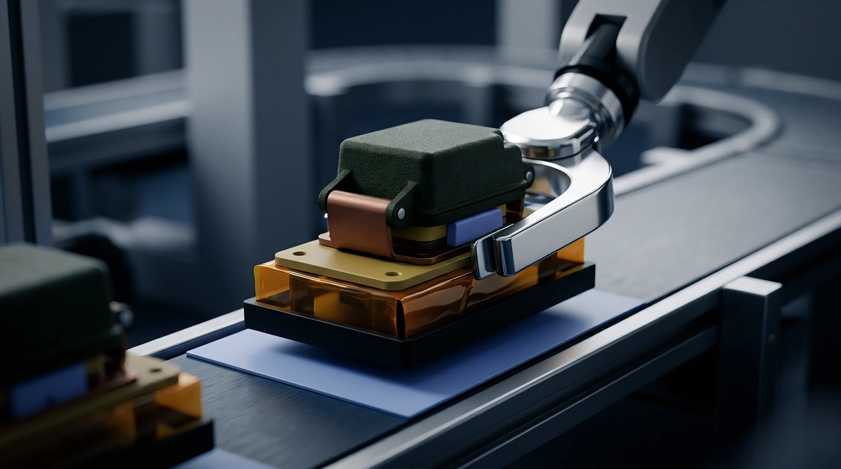
Electrolytic and Electroless Underplate Stack Ups
Standard substrate metallization sequence begins with a copper alloy base material followed by a intermediate nickel deposit. The leadframe specification defines minimum thickness values for each layer to withstand assembly and handling. For standard commercial surface-mount packages subject to standard reflow, a nickel thickness of one point two seven micrometers, equivalent to fifty microinches, represents the baseline industry standard.
Extended component bake cycles demanded by moisture sensitivity level reset procedures require increased barrier thickness.
Component bake profiles executed at one hundred twenty-five degrees Celsius for forty-eight to ninety-six hours accelerate thermal activation. When component bakes extend to one hundred fifty degrees Celsius to remediate severe moisture exposure, standard nickel thickness proves insufficient. Copper outdiffusion reaches the outer surface finish within seventy-two hours under columnar nickel deposits.
Increasing the barrier deposit thickness to two point five4 micrometers, or one hundred microinches, extends barrier longevity by a factor of four. Columnar grains yield pathways. Amorphous deposits maintain barrier integrity at thinner dimensions.
An electrolytic nickel barrier layer held to 2.0 micrometers limits copper atom migration to under 50 nanometers after 168 hours at 150 degrees Celsius.
Platers frequently claim that localized grain boundary porosity stems from baseline copper substrate roughness rather than bath contamination or insufficient bath agitation.


Kinetics
Atomic migration speeds through thin metal coatings depend heavily on ambient temperature profiles. Thermal activation provides the kinetic energy required for copper atoms to dislodge from their lattice positions and transport into the nickel underplate matrix. Mathematically, this process obeys Fick’s laws of diffusion, modified for grain boundary and bulk movement mechanisms.
At room temperature, copper diffusion into nickel is negligible, measuring less than ten to the power of minus twenty-four square meters per second.
Elevating component temperature during extended bake cycles dramatically accelerates atom transport. Thermal activation follows the Arrhenius relationship, where the diffusion coefficient D scales exponentially with absolute temperature. Bake cycles designed to drive out absorbed moisture at one hundred twenty-five degrees Celsius or one hundred fifty degrees Celsius shift diffusion kinetics into a regime where grain boundary transport dominates.
Temperature accelerates atom transport. Diffusion rates increase exponentially.
Arrhenius Thermal Activation and Diffusion Flux
Determining the effective diffusion coefficient requires separating volume diffusion from grain boundary diffusion. For copper diffusing into electroplated nickel, the volume diffusion pre-exponential factor D0 equals two point seven times ten to the power of minus five square meters per second, with an activation energy Ea of two hundred fifty-six kilojoules per mole. Grain boundary diffusion features a much lower activation energy of approximately one hundred thirty-five kilojoules per mole, alongside a pre-exponential factor of two point seven times ten to the power of minus seven square meters per second.
Because the activation energy for grain boundary diffusion is nearly half that of bulk diffusion, grain boundary transport accounts for over ninety-nine percent of total copper atom flux at component bake temperatures below two hundred degrees Celsius. The boundary diffusion width, typically assigned a value of zero point five nanometers, serves as the critical geometric parameter in Hart’s equation for effective diffusion calculation. Amorphous electroless nickel-phosphorus coatings eliminate grain boundaries, forcing diffusion to proceed purely via the high-activation-energy bulk mechanism.

Calculated Barrier Consumption during High Temperature Bake
Predicting how fast an intermediate nickel plating depletes involves solving Fick’s second differential equations under moving boundary conditions. As copper diffuses into the nickel underplate, an intermetallic layer forms at the copper-nickel interface. Simultaneously, copper atoms that traverse the full nickel thickness reach the outer surface finish, reacting with tin to form copper-tin intermetallics or oxidizing upon exposure to atmospheric oxygen.
Bake cycles consume barrier material. Thicker coatings delay failure.
Consider a component specification subjecting leadframes to extended dry-pack bake operations. The penetration depth x of copper into the nickel layer over time t is estimated using the square root relationship where x equals the square root of the product of two, the effective diffusion coefficient D, and time t. Operating at one hundred fifty degrees Celsius, grain boundary diffusion in electroplated nickel yields an effective diffusion coefficient of four point two times ten to the power of minus eighteen square meters per second.
| Bake Temperature (C) | Bake Duration (Hours) | Underplate Microstructure | Effective Diffusion Coeff (m2/s) | Copper Penetration Depth (um) | Minimum Recommended Nickel (um) |
|---|---|---|---|---|---|
| 125 | 24 | Electroplated Columnar | 3.1e-19 | 0.23 | 1.27 |
| 125 | 96 | Electroplated Columnar | 3.1e-19 | 0.46 | 1.50 |
| 125 | 168 | Electroplated Columnar | 3.1e-19 | 0.61 | 1.80 |
| 150 | 24 | Electroplated Columnar | 4.2e-18 | 0.85 | 2.00 |
| 150 | 96 | Electroplated Columnar | 4.2e-18 | 1.70 | 2.80 |
| 150 | 168 | Electroplated Columnar | 4.2e-18 | 2.25 | 3.50 |
| 150 | 168 | Electroless High-P (Amorphous) | 1.8e-20 | 0.15 | 1.27 |
| 175 | 48 | Electroplated Columnar | 4.5e-17 | 3.94 | 5.00 |
The tabulated calculations illustrate the severe impact of extended thermal budgets. Subjecting columnar electroplated nickel to a one hundred fifty degree Celsius bake for ninety-six hours causes copper penetration to reach one point seven zero micrometers. Standard one point two seven micrometer plating fails entirely under this thermal profile, allowing copper to saturate the underplate and contaminate the solderable outer surface finish.
Switching to high-phosphorus electroless nickel drops the effective diffusion coefficient by over two orders of magnitude, limiting copper penetration to zero point one five micrometers under identical conditions.
Grain boundary diffusion dominates copper transport below two hundred degrees Celsius, making amorphous nickel structures far more effective than columnar electrodeposits.
Doubling the barrier thickness buys four times the effective protection against thermal diffusion before grain boundary saturation occurs.
Intermetallics
Amorphous deposits containing eight to twelve weight percent phosphorus act as superior physical barriers compared to electroplated variants. The Absence of grain boundaries forces copper atoms to move via lattice volume substitution, which requires significantly higher activation energy. However, prolonged exposure to heat drives secondary thermodynamic reactions at both interfaces of the underplate layer.

Does Electroless Nickel Prevent Copper Outdiffusion during Bake?
Electroless nickel deposits significantly retard copper migration, yet they introduce distinct microstructural transformation mechanisms under extended thermal stress. When components undergo continuous bake cycles exceeding one hundred twenty-five degrees Celsius, nickel reacts with the surface tin finish to form a nickel-tin intermetallic compound layer, predominantly Ni3Sn4. As nickel is consumed in this reaction, phosphorus accumulates directly beneath the growing intermetallic film.
This localized segregation creates a phosphorus-rich layer containing Ni3P phase precipitation. The formation of Ni3P releases mechanical stress and produces micro-voids at the intermetallic interface. If copper eventually breaks through a thin electroless barrier, a complex ternary phase containing copper, nickel, and tin forms, severely compromising mechanical bond integrity.
Heat accelerates intermetallic growth.
The following failure modes highlight structural degradation risks during prolonged thermal baking:
- Copper-tin intermetallic growth occurs when substrate atoms breach the underplate, forming Cu6Sn5 and Cu3Sn phases that deplete active surface solderability.
- Kirkendall void coalescence develops within the copper-nickel boundary due to asymmetrical atomic diffusion rates between adjacent metal layers.
- Surface oxide passivation takes place as diffused copper reaches the outer surface and reacts with atmospheric oxygen to form insoluble copper oxides.
- Sub-surface phosphorus enrichment forms a brittle nickel-phosphide layer beneath the solder interface during extended thermal processing of electroless coatings.

Phase Transformations and Subsurface Void Mechanics
When tin reacts with copper, intermediate intermetallic compounds form at the boundary interface. The primary equilibrium phases consist of Cu6Sn5, known as the eta-phase, and Cu3Sn, known as the epsilon-phase. Cu6Sn5 forms rapidly at lower temperatures, whereas Cu3Sn requires higher thermal budgets and forms adjacent to the copper substrate.
The growth of Cu3Sn consumes copper atoms rapidly, creating vacancy fluxes toward the base metal.
Unbalanced vacancy fluxes lead directly to Kirkendall voiding. Because copper diffuses into nickel faster than nickel diffuses into copper, micro-cavities condense along the interface boundary. Under extended component bake conditions, these individual nanoscale vacancies coalesce into continuous micro-cracks.
Voiding degrades joint integrity. Subsurface micro-cracks act as stress concentrators during post-bake lead forming or thermal shock testing.
Surface oxidation poses a parallel reliability threat. When outdiffused copper reaches a matte tin or gold surface layer, it combines with oxygen to create Cu2O and CuO films. These oxides cannot be dissolved by standard mild rosin fluxes used in surface-mount assembly.
Surface oxides prevent bonding. Wetting times increase, leading to pinholes and un-wetted lead areas.
Substrate lots baked past their thermal barrier capacity produce micro-voiding that causes solder joint shear failures during thermal shock testing.


Solderability
Evaluating component lead finish degradation relies on measuring zero-cross time and maximum wetting force. Dip-and-look solderability testing per J-STD-002 provides qualitative assessment, but quantitative wetting balance testing reveals precise kinetic degradation. Fresh leadframe surfaces display zero-cross times under one second and maximum wetting forces exceeding two hundred micronewtons per millimeter.
Extended baking shifts these metrics drastically.
Thermal exposure drives copper to the surface, where oxidation suppresses tin wetting. When copper concentration in the surface layer exceeds zero point five atomic percent, zero-cross wetting times exceed two point five seconds. Flux fails to clean the oxidized surface effectively within standard reflow windows.
Oxides destroy solder wetting. Assembly lines experience dewetting and solder bridging.

Wetting Balance Parameters after Thermal Exposure
Testing executed on component leads following varying bake durations documents progressive loss of solderability. Components subjected to twenty-four hours of dry heat at one hundred twenty-five degrees Celsius retain acceptable wetting performance when protected by a standard nickel underplate. Extending the bake duration to ninety-six hours increases zero-cross time by eighty percent on electroplated columnar nickel finishes.
Beyond one hundred sixty-eight hours, wetting forces drop below one hundred micronewtons per millimeter, indicating severe surface contamination.
Applying an appropriate surface finish over the nickel barrier layer mitigates surface oxidation risks. Matte tin plating at a thickness of seven to twelve micrometers provides a sacrificial tin reservoir. Extended baking consumes a portion of this tin layer to form Ni3Sn4 intermetallics, but unreacted surface tin remains available for soldering.
Thin immersion gold finishes, by contrast, offer no thickness reserve. Gold dissolves instantly into molten solder, exposing any underlying nickel or copper oxides directly to the solder wave.
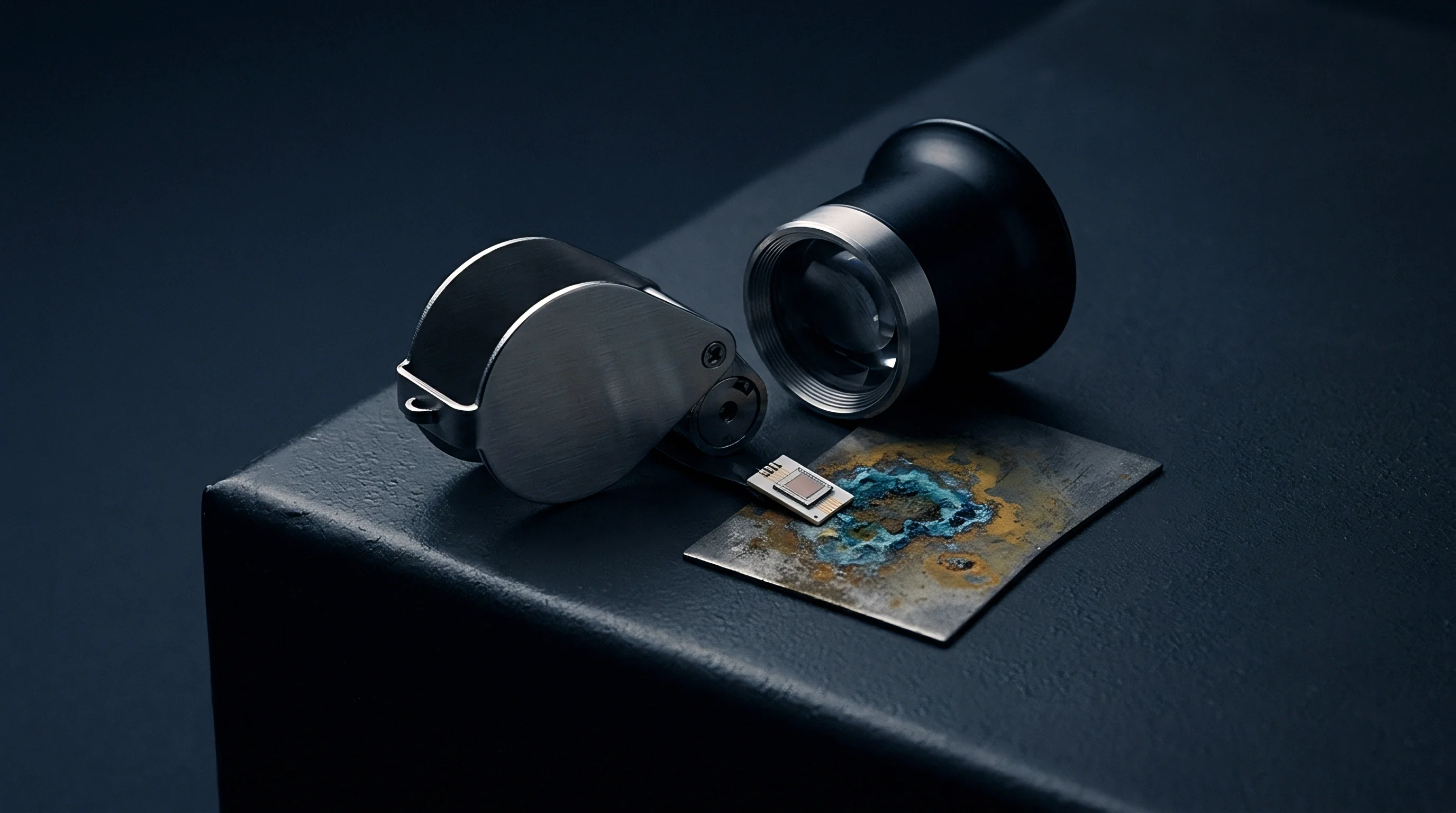
Surface Finish Options for High Thermal Budgets
Choosing between active surface coatings alters how components tolerate extended high-heat conditioning. The selection of top-level finish determines the permissible bake parameter window before solderability declines below manufacturing standards.
| Surface Finish Architecture | Underplate Specification | Max Bake Temp (C) | Max Duration (Hours) | Post-Bake Wetting Performance | Relative Finish Cost Index |
|---|---|---|---|---|---|
| Matte Tin (8-12 um) | Sulfamate Ni (1.27 um) | 125 | 48 | Excellent (Zero-cross < 1.0s) | 1.00 |
| Matte Tin (8-12 um) | Sulfamate Ni (2.54 um) | 125 | 168 | Good (Zero-cross < 1.5s) | 1.15 |
| Electroless Ni / Immersion Au (ENIG) | Electroless Ni-P (3.0 um) | 150 | 96 | Good (Zero-cross < 1.2s) | 2.40 |
| Electroless Ni / Pd / Au (ENEPIG) | Electroless Ni-P (3.0 um) | 150 | 168 | Superior (Zero-cross < 0.8s) | 3.10 |
| Pre-Plated Leadframe (Ni/Pd/Au) | Flash Ni (0.5 um) | 125 | 24 | Fail (Dewetting observed) | 1.80 |
The comparative data establishes clear trade-offs between processing cost and thermal endurance. Standard matte tin over a thick sulfamate nickel layer survives one hundred sixty-eight hours at one hundred twenty-five degrees Celsius without critical wetting loss. However, high-temperature bakes at one hundred fifty degrees Celsius demand advanced noble metal finishes.
Electroless nickel palladium immersion gold (ENEPIG) maintains superior wetting performance after extended thermal exposure, as the intermediate palladium layer acts as a secondary barrier against nickel dissolution into the gold layer.
IPC J-STD-002 Class 3 mandates zero pinhole exposure and greater than ninety-five percent solder coverage following steam aging or dry heat preconditioning.
Quality audit sequences for high-reliability component lots follow an established four-stage inspection process:
- Receive batch samples prior to component lot release.
- Perform cross-sectional polishing and optical examination.
- Conduct sequential electrochemical reduction analysis to quantify surface copper oxides.
- Subject test coupons to dip and look solderability testing per IPC standards.
Incorporating IPC-4552 Class 3 specification notes into procurement drawings shifts financial liability to the plater whenever nickel thickness drops below one point two seven micrometers.


Verification
Quantitative measurement of thin metal interfaces relies on surface-sensitive spectroscopy instruments. Validating barrier integrity requires non-destructive verification of deposit thickness alongside destructive chemical profiling of interdiffused interfaces. Standard X-ray fluorescence, or XRF, instruments measure total nickel and surface finish thickness quickly, but lack the depth resolution needed to detect nanoscale copper migration within grain boundaries.
Advanced diagnostic techniques resolve interface chemistry at nanometer scales. Auger electron spectroscopy, combined with ion beam sputtering, generates precise compositional depth profiles through multi-layer stack-ups. Profiling tracks elemental concentration of copper, nickel, tin, and oxygen from the outer surface down to the substrate alloy.
Auger depth profiles reveal diffusion. Plating baths require strict monitoring.
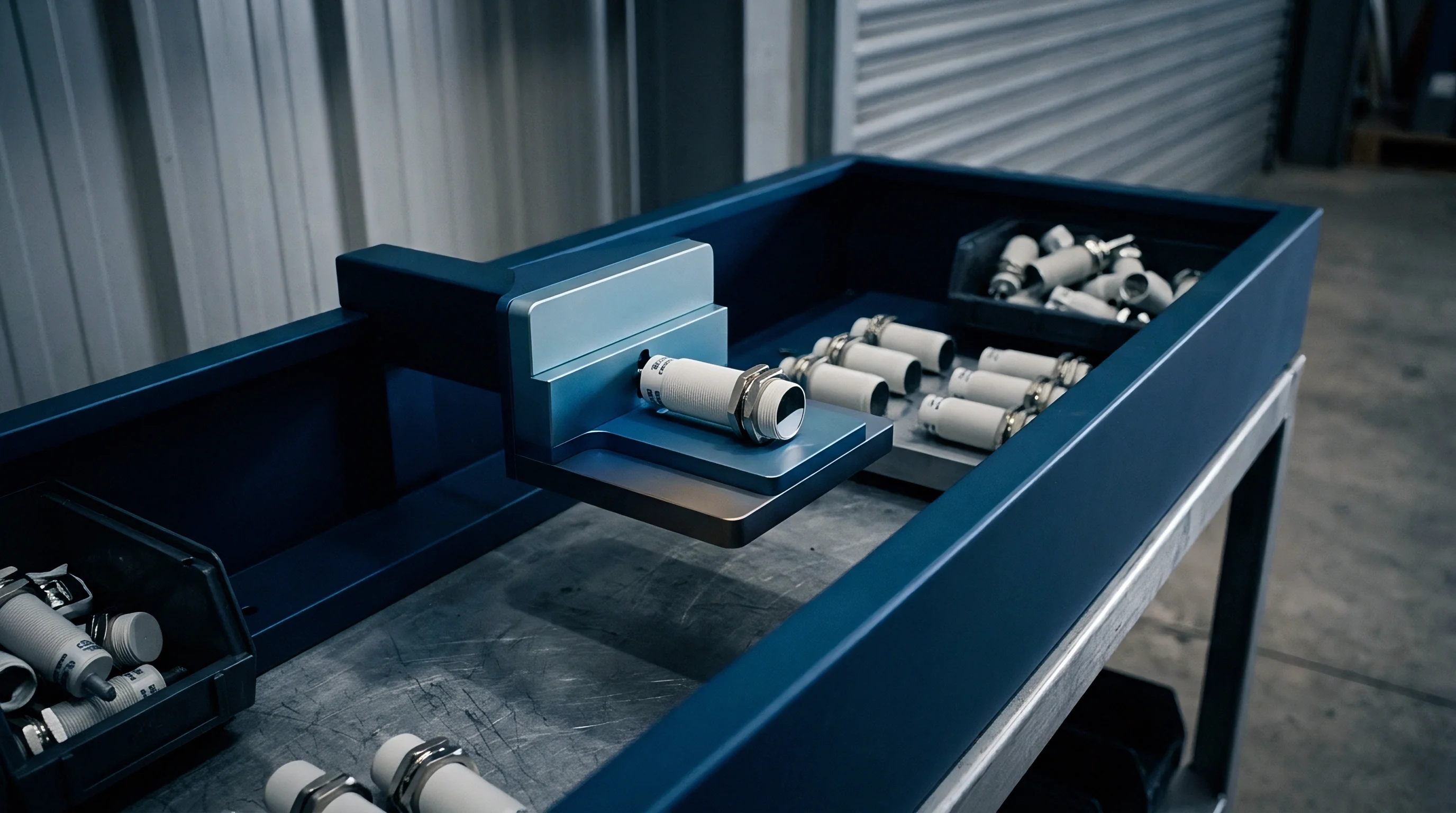
Analytical Depth Profiling and Microscopic Diagnostics
Cross-sectional analysis using Scanning Electron Microscopy paired with Energy Dispersive X-ray Spectroscopy provides structural insight into intermetallic growth. Resolving thin intermetallic sub-layers requires high-resolution Field Emission SEM operated at low accelerating voltages to minimize the electron interaction volume. For sub-nanometer interface detail, Focused Ion Beam milling prepares ultra-thin lamellae for Transmission Electron Microscopy examination.
TEM imaging coupled with STEM-EDS mapping reveals exact spatial distributions of copper within nickel grain boundaries. TEM cross sections confirm layer integrity. STEM-EDS detects localized copper concentration spikes along columnar boundaries long before copper breaks through to the outer surface finish.
This early detection capability allows component packaging engineers to catch barrier breakdown prior to widespread assembly failure.

Lot Acceptance Protocols for Extended Bake Components
Establishing incoming lot quality criteria requires defining clear sampling frequencies and failure limits. Procurement specifications for components intended for extended bake cycles must incorporate explicit testing protocols. Suppliers must certify minimum barrier thickness, phosphorus content ranges for electroless layers, and post-bake solderability margins.
The following contract specifications ensure robust barrier compliance across procurement batches:
- X-ray fluorescence calibration standards must be verified against certified reference materials for thin nickel deposits on copper substrates.
- Auger electron spectroscopy qualification thresholds mandate that surface copper concentrations remain below zero point five atomic percent after standard bake conditioning.
- Cross-sectional scanning electron microscopy criteria define acceptable intermetallic thickness caps and prohibit continuous Kirkendall void arrays at metal boundaries.
| Diagnostic Technique | Spatial / Depth Resolution | Detection Limit | Primary Measurement Role | Destructive Test Status |
|---|---|---|---|---|
| X-ray Fluorescence (XRF) | 10 um spatial / 50 nm depth | 0.1 weight percent | Total film thickness screening | Non-destructive |
| Auger Electron Spectroscopy (AES) | 100 nm spatial / 1 nm depth | 0.1 atomic percent | Elemental depth profiling | Destructive (Sputter etch) |
| FE-SEM with EDS | 5 nm spatial / 100 nm depth | 0.5 weight percent | Intermetallic phase imaging | Destructive (Cross section) |
| TEM with STEM-EDS | 0.2 nm spatial / 0.5 nm depth | 0.05 atomic percent | Grain boundary copper mapping | Destructive (FIB lamella) |
Implementing rigorous analytical verification protects high-reliability manufacturing programs from premature field failures. Multi-layer plating processes involve complex chemical interactions that cannot be assessed through simple visual inspection or standard thickness checks. Comprehensive material qualification verifies that component leadframe underplates survive severe thermal environments during moisture remediation and extended storage.
X-ray fluorescence measurement errors expand rapidly when underplate thickness falls below five hundred nanometers.
Whether non-destructive eddy-current sensors can reliably distinguish amorphous nickel-phosphorus phases from recrystallized structures during high-speed inline component inspection remains unanswered.