Modeling Time Dependent Anchor Stress Coupling in Tactical MEMS Gyroscopes
Anchor stress relaxation shifts micro-resonator mode matching, requiring stress-isolating central mounts and real-time piezoresistive compensation to hold tactical bias stability.


Transduction
Mounting strain transfers directly from packaging substrates into single-crystal silicon anchor structures, altering the resonant characteristics of tactical micro-resonators. Mechanical stress applied to an anchor site shifts the local elastic modulus through piezoresistive and stress-stiffening coefficients. Silicon springs store elastic energy.
When an anchor experiences an asymmetric strain tensor, the drive and sense modes of a quad-mass or ring resonator undergo divergent frequency shifts. Equal stiffness changes across orthogonal axes maintain modal alignment. Asymmetric strain distributions induce modal splitting, defined as the difference between sense and drive resonant frequencies.
Anchors transfer substrate strain. Tactical MEMS gyroscopes operating with high mechanical quality factors depend on matched modal frequencies to achieve maximum mechanical gain. A mechanical frequency mismatch degrades the velocity amplitude of the sense mode, causing direct attenuation of the scale factor.
Mechanical stress altering spring constants shifts the zero-rate bias by introducing quadrature forces. Demodulation electronics convert phase-shifted quadrature signals into uncommanded rate signals. Controlling anchor strain coupling requires precise evaluation of the mechanical interconnect chain between the die, die-attach adhesive, ceramic package base, and host printed circuit board.
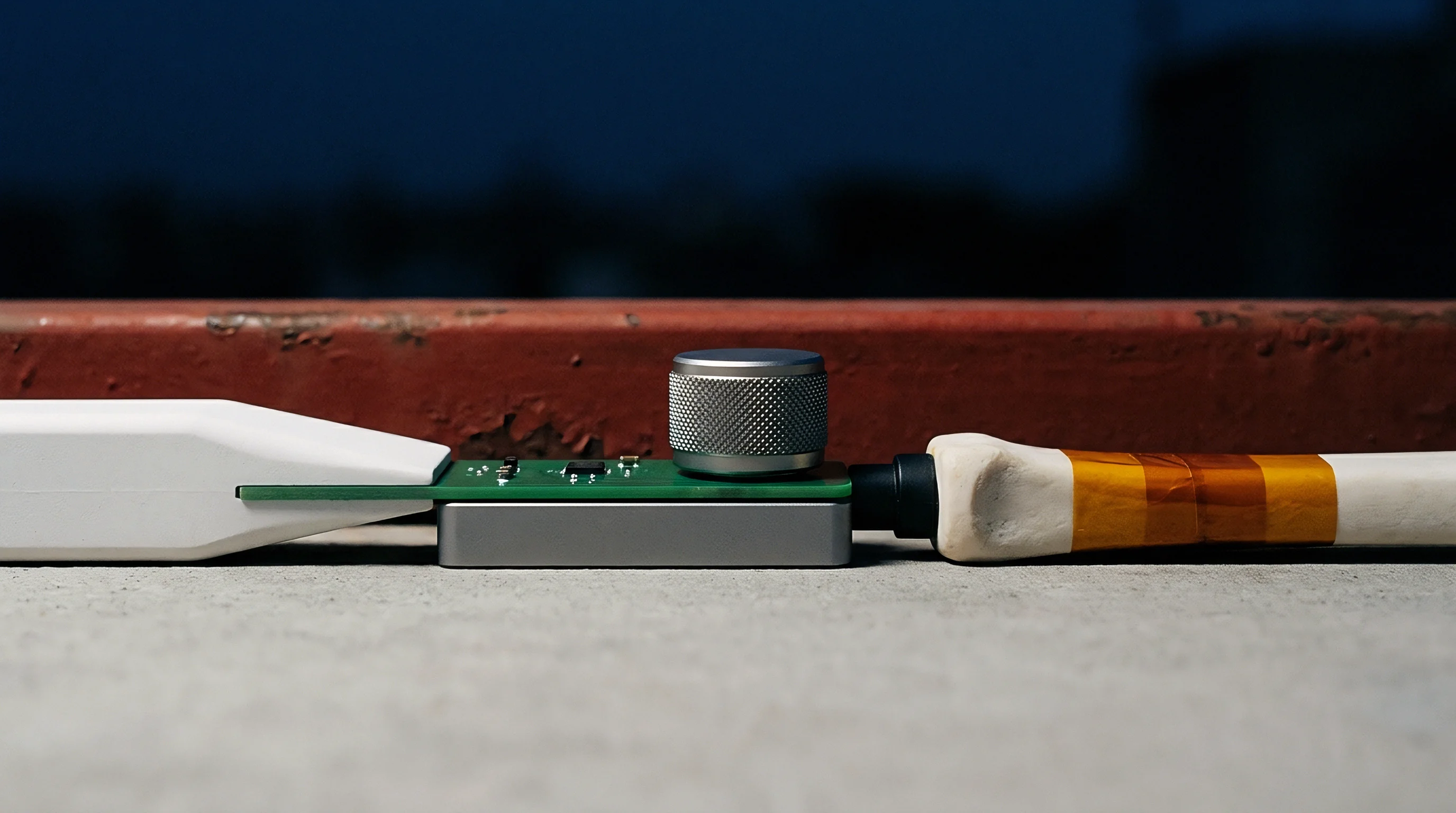
Mechanical Strain Pathways in Substrate Assemblies
Thermal expansion mismatches generate static stress fields upon cooling from die-attach cure temperatures. Coefficients of thermal expansion differ between single-crystal silicon, die-attach media, and alumina ceramic packages. Elastic modulus variations across these interfaces determine the magnitude of strain delivered to the silicon anchor boundaries.
| Die-Attach Material | Elastic Modulus (GPa) | CTE Mismatch (ppm/K) | Viscoelastic Relaxation Rate (%/1000hr at 85C) | Anchor Stress Sensitivity (Hz/MPa) |
|---|---|---|---|---|
| Eutectic Gold-Tin (Au80Sn20) | 59 | 13.4 | 0.02 | 1.45 |
| High-Lead Solder (Pb92.5Sn5Ag2.5) | 16 | 22.0 | 0.85 | 0.42 |
| Silver-Filled Conductive Epoxy | 7.5 | 35.0 | 4.60 | 0.18 |
| Low-Melting Glass Frit | 42 | 6.8 | 0.00 | 1.10 |
Rigid bonding media like gold-tin eutectic alloys deliver lower long-term relaxation while transmitting peak thermal expansion stress directly to the silicon lattice. Soft polymeric adhesives attenuate transient package strain at the expense of continuous time-dependent mechanical creep. Polymer networks undergo structural relaxation over operational lifetimes, shifting the baseline stress state at the silicon anchor points.
Failure to model package stress transmission results in thermal bias hysteresis that exceeds tactical inertial limits, causing navigation drift of tens of kilometers over extended flight profiles.

Creep
Viscoelastic relaxation within polymeric die-attach layers changes the mechanical boundary conditions at silicon anchor sites over hundreds of operating hours. Post-cure polymer cross-linking continues at elevated temperatures, producing localized volume shrinkage and shear modulus evolution. The resulting mechanical relaxation follows multi-exponential decay patterns, altering the static strain field coupled into the micro-resonator suspension arms.
Stress alters resonance. Time-dependent stress migration alters drive-axis stiffness independent of ambient thermal shifts. As polymer chains realign under residual bonding stress, the anchor footprint rotates by fraction-arcsecond angles.
This mechanical rotation alters the drive-to-sense energy coupling ratio, generating continuous drift in the zero-rate offset.
Die-attach viscoelastic relaxation under continuous thermal exposure at 85 degrees Celsius generates bias stability degradation of 0.45 degrees per hour over a 1000-hour operating window.
Thermal cycling accelerates viscoelastic flow in polymeric adhesives. Operating a sensor across broad thermal ranges forces the die-attach layer through non-linear stress-strain hysteresis loops. Upon returning to room temperature, the residual strain state at the anchor differs from its initial state, shifting baseline calibration coefficients.
Moisture absorption within epoxy networks further lowers the glass transition temperature, altering relaxation time constants during field deployment.
Die-attach vendors frequently assert that package-induced bias drift originates from user printed circuit board mounting stress rather than internal polymer cross-link relaxation.


Joint
Anchor geometry determines how effectively a micro-resonator isolates its active spring system from external package strain. Single central anchor topologies route external package strain symmetrically around a central axis, preserving modal symmetry. Perimeter multi-anchor configurations transmit differential expansion across package headers directly into individual resonator springs, driving mode-split divergence.

Where Does Substrate Strain Break Resonance Symmetry inside Symmetric Anchors?
Substrate flexure forces localized bending moments into silicon anchor roots. Non-uniform strain distribution across anchor pads alters differential spring constants. Dynamic mechanical modeling must map the complete six-degree-of-freedom strain tensor at each anchor interface across temperature gradients.
Structural failure modes originating at the anchor interface disrupt gyro performance through several distinct physical mechanisms:
- Asymmetric elastomeric shear shifts the drive-axis spring constant while leaving the sense axis unconstrained.
- Solder bump voiding creates localized strain peaks at adjacent package pins under thermal cycling environments.
- Substrate warpage coupling converts board-level bending moments into shear forces along silicon anchor boundaries.
- Interfacial delamination alters anchor stiffness boundaries, causing abrupt steps in baseline resonant frequency.
Package geometry dictates strain paths. Micro-machined stress-isolation rings surrounding central anchor pads dissipate substrate strain through flexural beam compliance. These isolation structures filter high-frequency package strain before it reaches the active resonator mass.
| Anchor Design Configuration | Effective Footprint Area (mm2) | Direct Strain Transfer Ratio (dB) | Modal Split Shift Rate (Hz/MPa) | Cross-Axis Coupling Coefficient (%) |
|---|---|---|---|---|
| Single Center Post | 0.09 | -42.5 | 0.04 | 0.01 |
| Dual Symmetric Axis | 0.36 | -28.1 | 0.28 | 0.14 |
| Quad Perimeter Frame | 1.44 | -12.4 | 1.82 | 1.25 |
| Isolated Ring Frame | 0.25 | -36.8 | 0.08 | 0.03 |
Incorporating ISO 16063 vibration mounting compliance standards within procurement specifications forces packaging suppliers to guarantee anchor stress transfer functions under operational torque limits.

Deformation
Calculating time-dependent modal split and bias drift demands an integrated numerical routine combining finite element strain extraction with analytical resonator dynamics. Consider a tactical silicon tuning fork micro-resonator operating at a nominal drive frequency of 20,000 Hz, featuring an initial modal frequency split of 0.20 Hz. The mechanical assembly utilizes a silver-filled epoxy die-attach exhibiting an initial residual compressive stress of 12.0 MPa along the primary anchor axis post-cure.
The anchor stress coupling coefficient for this spring geometry measures 1.40 Hz/MPa along the drive spring direction. Over a 500-hour dwell at 70 degrees Celsius, viscoelastic relaxation within the adhesive layer reduces residual stress according to a two-term Prony series response:
σ(t) = σ0 · left
Using relaxation coefficients alpha-infinity equal to 0.85, alpha-one equal to 0.10, alpha-two equal to 0.05, tau-one equal to 50 hours, and tau-two equal to 400 hours, the residual stress at 500 hours evaluates to 10.3716 MPa. The change in anchor stress over this operational period equals 1.6284 MPa.
Multiplying this stress change by the coupling coefficient yields a modal split shift of 2.28 Hz. In a closed-loop capacitive demodulation chain with a demodulation scale factor of 3.42 degrees per hour per Hertz of split shift, this modal drift induces a uncommanded zero-rate bias shift of 7.80 degrees per hour.
Compliance with MIL-STD-883 Method 1010 condition C thermal cycling mandates continuous tracking of zero-rate output drift across five hundred thermal shocks to expose latent package strain.
Uncompensated creep destroys bias stability. Thermally activated stress migration alters the modal alignment continuous matrix. Anchoring a sensor mass through a single symmetrical central point always decouples external package stress far more effectively than distributing anchors along die edges.

Compensation
Real-time compensation of anchor strain requires embedded stress sensors colocated with silicon suspension anchors. Piezoresistive Wheatstone bridges diffused directly into the silicon substrate adjacent to anchor roots output differential voltages proportional to local strain tensors. Signal-chain microcontrollers sample stress bridge voltages alongside core temperature sensors to compute dynamic correction factors.
Stress bridges track internal strain. Compensation schemes process piezoresistive outputs through polynomial calibration matrices to predict instantaneously induced spring stiffness changes.
- Map the baseline modal frequency split across the operational temperature range inside an environmental chamber.
- Record output voltages from integrated piezoresistive stress sensors positioned adjacent to silicon anchor structures at ten-degree temperature steps.
- Fit a multi-term viscoelastic Prony series model combining thermal history data and real-time strain bridge outputs.
- Inject real-time phase compensation parameters into the sense-channel demodulation matrix during sensor operation.
Modal splitting creates quadrature error. High-speed signal processing engines adjust drive amplitude and sense demodulation phase to null strain-induced quadrature forces. Digital filtering must balance stress bridge sampling rates against overall system power budgets.
Continuous monitoring of stress sensor bridge voltage provides an indirect measurement of silicon spring deformation long before thermal equilibrium is reached.
Whether real-time algorithmic stress compensation can reliably predict long-term structural creep under random vibrational profiles remains an active area of investigation.
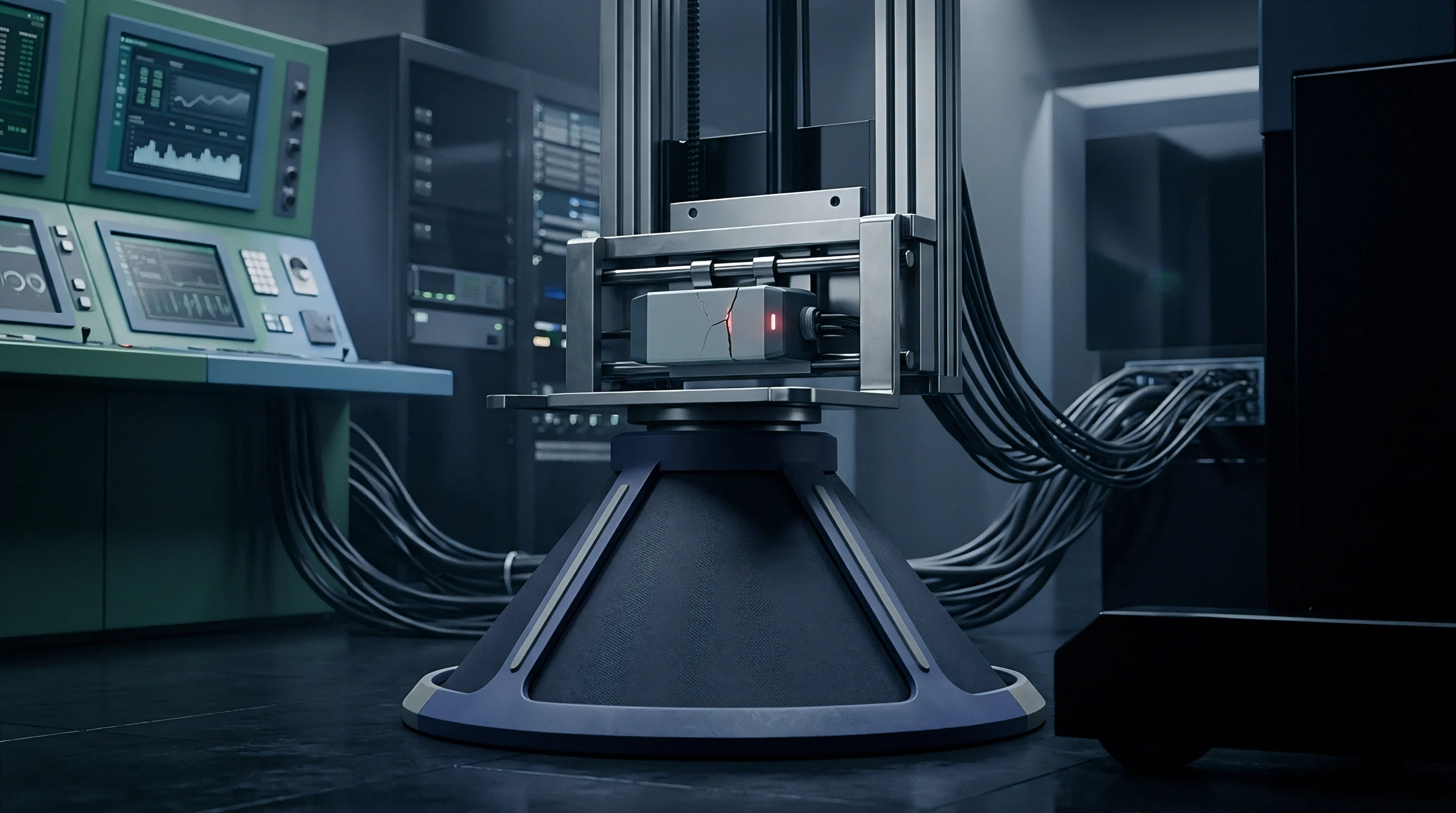
Validation
Verifying time-dependent anchor stress coupling requires environmental testing protocols designed to separate polymer relaxation from silicon lattice degradation. Vacuum bakeout procedures pre-condition assembled sensor cores, accelerating volatile outgassing and stabilizing epoxy cross-link density prior to final hermetic sealing. Environmental testing chambers subject packaged sensors to continuous thermal-vacuum profiles while monitoring high-resolution rate outputs and drive-loop phase margins.
Bakeout cycles stabilize polymer networks. Qualification protocols assess long-term bias stability using Allan variance processing across operating temperatures. High-temperature storage audits isolate viscoelastic relaxation rates by holding devices at elevated thermal states while verifying zero-rate bias stability shifts over thousand-hour intervals.
Acceptance testing procedures demand strict screening criteria for all high-reliability inertial measurement units:
- Pre-seal vacuum bakeout eliminates volatile organics that drive post-encapsulation moisture strain in polymeric adhesives.
- High-temperature storage audits quantify true viscoelastic relaxation coefficients separate from silicon crystal dislocation movement.
- Multi-axis mechanical strain screening isolates printed circuit board flexural coupling from internal header stress.
- Thermal shock hysteresis evaluation measures residual zero-rate offset shifts following extreme thermal transitions.
| Verification Test Procedure | Test Duration / Cycle Count | Monitored Sensor Parameter | Pass/Fail Acceptance Criteria |
|---|---|---|---|
| High-Temperature Storage Dwell | 1000 Hours at 105C | Allan Variance Bias Instability | Shift < 0.10 deg/hr |
| Thermal Shock Cycling | 500 Cycles (-55C to +125C) | Zero-Rate Offset Hysteresis | Shift < 0.25 deg/hr |
| Random Vibration Dwell | 20g RMS (20Hz to 2kHz) | Drive/Sense Modal Split Delta | Shift < 0.05 Hz |
| Accelerated Moisture Soak | 168 Hours at 85C / 85% RH | Piezoresistive Bridge Baseline | Drift < 15 uV/V |
Silicon lattice symmetry guarantees invariant stiffness characteristics until package mounting strain breaks structural equilibrium.
Inertial sensor sourcing specifications require clear quantification of die-attach material properties and package stress isolation efficiency. Wafer fabrication plants and packaging facilities must certify stress relaxation limits across raw material lots. Integrating stress-aware physical models directly into sensor signal processing software protects tactical navigation hardware against continuous mechanical drift over operational lifetimes.