Mathematical Tumble Test Algorithms Decoupling Gravity Vectors from Sensor Bias
Scalar gravity norm tumble test algorithms decouple MEMS accelerometer bias, scale factor, and cross-axis misalignments without requiring precision angular tracking hardware.
Kinematics
A triaxial accelerometer outputting raw voltage or digitally quantized counts combines true local gravity with deterministic sensor imperfections. The gravity vector provides an invariant baseline. In ideal conditions, placing a sensor at rest yields a three-dimensional vector measurement whose magnitude exactly equals the local gravitational acceleration.
Physical micro-electromechanical systems (MEMS) accelerometers introduce systematic distortions through individual axis gain errors, DC bias offsets, structural non-orthogonality between sensitive axes, and cross-axis alignment errors originating from silicon die bonding tolerances.
The mathematical model mapping the uncalibrated sensor output vector to the true acceleration vector takes the form of a linear transformation followed by an additive bias vector. Let a_raw represent the 3-by-1 vector of measured raw sensor outputs along the sensor frame x, y, and z axes. The relationship to the true acceleration vector a_true is governed by:
a_raw = S · M · a_true + b + η
Here, S represents a 3-by-3 diagonal matrix containing the individual axis scale factors, M represents a 3-by-3 lower-triangular non-orthogonality matrix accounting for cross-axis coupling, b represents the 3-by-1 DC bias vector, and η denotes broad-band zero-mean sensor noise. The non-orthogonality matrix M models the geometric misalignments between the mechanical axes of the sense structure, where off-diagonal terms quantify the physical angle deviations from nominal ninety-degree orthogonal alignment.

Triaxial Acceleration Vector Distortion Mechanisms
Static bias shifts with mounting stress. Silicon MEMS proof-mass structures experience mechanical strain during substrate mounting, lead-frame soldering, and plastic package encapsulation. This residual mechanical stress modifies the rest position of the capacitive sensing fingers, generating a fixed DC offset in zero-g conditions.
Thermal expansion coefficient mismatches between the silicon die, adhesive epoxy, and ceramic substrate further drive bias changes across operating temperatures.
Physical manufacturing limits in deep reactive-ion etching (DRIE) prevent perfectly perpendicular comb fingers and spring flexures. When an acceleration acts purely along the sensor frame x-axis, microscopic axis misalignments produce an erroneous signal component on the y-axis and z-axis output channels. Combining scale factor errors, static bias offsets, and non-orthogonality transforms the spherical locus of ideal zero-g gravity measurements into a rotated, shifted triaxial ellipsoid in raw measurement space.

Algebraic Decoupling of Local Gravity Invariants
Tumble testing exploits the physical constraint that the Euclidean norm of the local gravity vector remains invariant regardless of sensor orientation in space. By placing the sensor in N static orientations relative to the earth reference frame, the unknown true acceleration vector for orientation i satisfies the magnitude constraint:
||a_true,i||2 = g2
Where g represents local gravitational acceleration, standardizing to 9.80665 m/s2 or normalized to exactly 1.0 g. Substituting the inverse sensor error transformation into the norm equation decouples sensor bias and scale factors from external orientation tracking hardware. The fundamental calibration objective simplifies to estimating the elements of inverse matrices T = (S · M)-1 and bias vector b such that the reconstructed acceleration vectors land precisely on a sphere of radius g.
| Error Component | Matrix Symbol | Independent Parameters | Physical Root Cause |
|---|---|---|---|
| Triaxial Bias Vector | b | 3 | Piezoresistive/capacitive resting stress, package strain, ASIC trim offset |
| Axis Scale Factors | S | 3 | Capacitance-to-voltage gain variations, spring constant drift, ADC reference scaling |
| Axis Non-Orthogonality | M | 3 | DRIE photolithography misalignment, die-attach tilt, package mounting rotation |
| Cross-Axis Sensitivity | C | 3 | Proof-mass out-of-plane flexure, asymmetric electrostatic feedback forces |
Failing to separate cross-axis misalignment terms from pure bias components corrupts downstream dead-reckoning filters, causing quadratic velocity drift errors exceeding forty meters per hour in unguided inertial navigation systems.
Sphere
Ellipsoid fitting algorithms transform uncalibrated raw acceleration datasets into unit-sphere representations without requiring prior knowledge of the test fixture inclination angles. Raw measurements collected across a multi-position tumble sequence form a locus of points defining a quadric surface in three-dimensional space. The implicit equation of an arbitrary quadric surface is expressed as a quadratic form containing six spatial coordinates and four linear terms.
Transforming the algebraic quadric parameters into physically meaningful sensor calibration parameters requires enforcing an ellipsoid constraint. The general algebraic representation of an ellipsoid is given by:
vT · A · v + BT · v + d = 0
Where v = T contains raw sensor readings, A is a 3-by-3 symmetric positive-definite matrix encoding ellipsoid shape and orientation, B is a 3-by-1 linear vector, and d is a scalar constant. Extracting the sensor parameters involves solving an overdetermined non-linear system of equations using least-squares optimization techniques.

Ellipsoid Fitting via Non Linear Least Squares
Minimizing the algebraic distance between raw sensor measurements and the quadric surface offers a computationally direct closed-form solution via singular value decomposition. Direct algebraic minimization exhibits noise sensitivity, biasing parameter estimates when sensor readings contain high broad-band noise levels.
- Initialize parameter vector containing baseline diagonal scale factors set to nominal datasheet gain and bias components set to zero.
- Collect static multi-position tumble raw acceleration datasets across N static test orientations.
- Compute estimated true acceleration vectors for every orientation using current calibration matrix parameters.
- Calculate scalar gravity residual norms by comparing computed vector magnitudes against known local gravity reference values.
- Construct Jacobian matrix containing partial derivatives of scalar gravity residuals with respect to bias, scale factor, and non-orthogonality terms.
- Solve normal linear equations using QR decomposition to derive update vector for parameter correction.
- Apply update vector to parameter matrix using damping factors to guarantee stable algorithm convergence.
- Repeat iteration steps until absolute change in scalar residual norm drops below defined convergence threshold.
Local gravity norms calculated across 24 static orientation positions yield residual fit errors below 120 micro-g when optimized using dampened Levenberg-Marquardt solvers.

Gauss Newton Convergence on Noise Corrupted Datasets
Geometric distance minimization provides superior parameter accuracy by calculating the actual spatial distance from each measurement point to the fitted ellipsoid surface. The non-linear objective function minimizes the sum of squared scalar gravity errors across N tumble positions:
E = ∑i=1. N ( || T · (a_raw,i – b) ||2 – g2 )2
Executing Gauss-Newton optimization iteratively updates parameter estimates by linearizing the objective function around current estimate values. When noise levels exceed 500 micro-g RMS, Gauss-Newton algorithms risk local divergence if initialized far from true parameter values. Implementing Levenberg-Marquardt regularization introduces a dynamic damping term to matrix inversions, ensuring smooth convergence from arbitrary initialization states.
| Tumble Orientations | Minimum Matrix Rank | Iterative Steps to Converge | Residual Bias Uncertainty | Scale Factor Residual Error |
|---|---|---|---|---|
| 6 Orientations (±x, ±y, ±z) | 6 | 14 | ±1.4 mg | ±1200 ppm |
| 12 Orientations (Cube Edges) | 9 | 8 | ±350 μg | ±280 ppm |
| 24 Orientations (Truncated Octahedron) | 9 | 5 | ±85 μg | ±65 ppm |
| 36 Orientations (Icosahedral Uniform) | 9 | 4 | ±42 μg | ±30 ppm |
The parameter state vector converges stably once local gravity norm variations between successive algorithm iterations drop below 10 nanometers per second squared per iteration cycle.

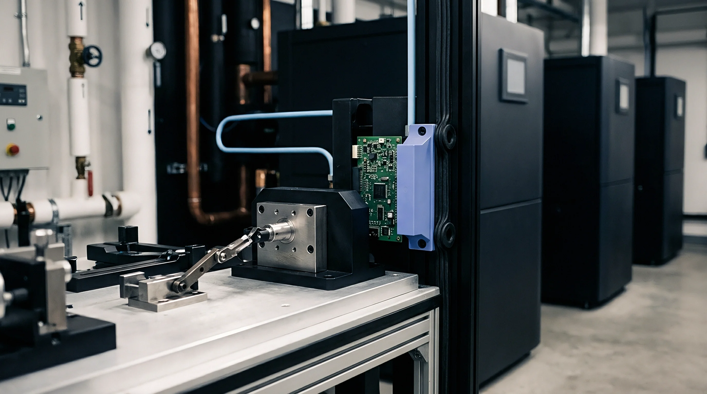
Rig
Physical test fixtures determine measurement quality during data capture. Utilizing physical positioning platforms with sub-arcsecond optical encoders allows independent verification of sensor mounting angles, but mathematical gravity-norm decoupling eliminates the absolute necessity for precision goniometric alignment.
When physical tumble tests take place on manual tilt fixtures or simple polyhedral blocks, fixture flexure, table inclination errors, and operator handling variations introduce local disturbances. The mathematical gravity decoupling algorithm treats fixture angle deviations as unmeasured intermediate rotation matrices that drop out entirely during scalar magnitude calculation.

Which Dynamic Orientation Profile Isolates Accelerometer Axis Crosstalk?
Dynamic movement sequences between static tumble positions generate transient mechanical vibrations, centrifugal accelerations, and structural ringing. Decoupling sensor bias from true gravity requires isolating static dwell windows from motion-induced transient regimes. Filtering raw sensor streams using sliding-window variance thresholds isolates pure gravitational static vectors.
A continuous tumbling profile incorporating smooth, constant-angular-velocity rotations around multiple axes allows continuous calibration data collection. Rotary motion introduces centripetal acceleration terms equal to ω × (ω × r), where ω represents angular velocity and r represents internal proof-mass offset relative to the rotation center. Keeping angular rotation rates below 0.05 radians per second maintains parasitic centripetal accelerations below 15 micro-g, rendering them negligible relative to primary gravity vector magnitude.
Standard IEC 60068-2-64 defines vibration rejection criteria for inertial sensor calibration rigs operating under industrial floor disturbances.
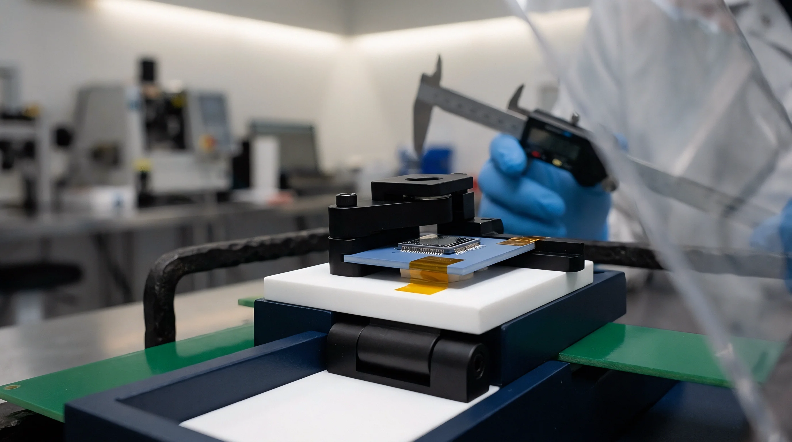
Mechanical Indexing Error and Fixture Runout Suppression
Mechanical indexing fixtures exhibit manufacturing tolerances including surface non-flatness, bearing runout, and axis orthogonality errors. Un-instrumented tumble test algorithms remove sensitivity to fixture orthogonality errors by enforcing scalar gravity invariance instead of spatial direction alignment.
- Polyhedral Machining Tolerances introduce angle deviations up to five arcminutes between adjacent faces, creating apparent direction shifts that scalar magnitude algorithms ignore.
- Table Leveling Drifts caused by floor settling or thermal expansion of mounting legs modify global reference frames without altering local scalar gravitational field magnitude.
- Thermal Expansion of Rotational Arms alters physical radius distances, creating variable centripetal acceleration contributions during dynamic rotation phases.
- Gravitational Field Anomaly Gradients caused by large metal masses near the test bench perturb local gravity acceleration values at parts-per-million levels.
Factory tumble fixtures are often subjected to quarterly optical re-alignment to account for production calibration discrepancies, even though scalar gravity norm routines remain mathematically invariant to fixture angular misalignment.


Residuals
Unmodeled higher-order error terms introduce systematic deviations into scalar gravity norm calculations. Standard linear models assume constant scale factors and perfectly straight sensitivity axes across the full measurement range. Real MEMS accelerometers exhibit non-linear deflection responses under higher acceleration levels, cross-axis g-sensitivity, and non-linear thermal drift dynamics.
Modeling non-linear response requires expanding the sensor model to include quadratic scale factor matrix K_2. The expanded accelerometer output equation becomes:
a_raw = S · M · a_true + K_2 · (a_true)2 + b + η
Second Order Acceleration Non Linearity Modeling
Quadratic scale factor non-linearity distorts the calibrated gravity norm symmetrically along positive and negative measurement directions. In a 1g tumble test, positive one-g readings experience a scale shift proportional to +K_2, while negative one-g readings shift by the same magnitude. Standard linear tumble algorithms absorb quadratic terms into effective linear scale factors, leading to bias estimation errors when sensors encounter multi-g operating environments.
Decoupling second-order non-linearity requires multi-g centrifuge testing or combined gravity-plus-vibration tumble sequences. A pure 1g static tumble test lacks sufficient input range variation to separate quadratic non-linearity coefficients from linear scale factors independently. Linear tumble algorithms assume quadratic coefficients remain within component datasheet boundaries.

Thermal Bias Coefficient Extraction during Tumble Cycles
Executing tumble test sequences inside an environmental chamber across ambient temperature profiles extracts temperature coefficients for bias vector b(T) and scale factor matrix S(T) simultaneously.
- Linear Thermal Bias Coefficients define first-order offset shifts expressed in micro-g per degree Celsius across standard operating ranges.
- Polynomial Scale Factor Thermal Drift quantifies capacitive sensitivity changes driven by silicon Young’s modulus variations over temperature.
- Hysteresis Temperature Offsets quantify permanent bias shifts caused by thermal stress relaxation inside package molding compounds during thermal cycling.
- Axis Cross-Talk Drift Coefficients model temperature-dependent structural warping that alters inter-axis mechanical orthogonality.
| Performance Characteristic | Automotive Grade MEMS | Industrial Grade MEMS | Tactical Grade MEMS | Methodology Footnote |
|---|---|---|---|---|
| Uncalibrated Bias Offset | ±50 mg | ±10 mg | ±1.5 mg | Measured at 25°C ambient zero-g state |
| Post-Tumble Residual Bias | ±1.2 mg | ±150 μg | ±15 μg | 12-position tumble algorithm at 25°C |
| Thermal Bias Drift (-40 to 105°C) | ±0.8 mg/°C | ±0.1 mg/°C | ±0.01 mg/°C | Chamber soak rate 1°C per minute |
| Scale Factor Non-Linearity | 0.5% Full Scale | 0.1% Full Scale | 0.01% Full Scale | Tested across ±2g to ±16g input ranges |
Component datasheets quoting uncalibrated bias stability without stating ambient thermal ramp rates conceal thermal hysteresis errors that exceed static calibration residuals.
How do real-time embedded algorithms distinguish genuine sensor structural hysteresis from thermal lag within ceramic package substrates during fast temperature transients?


Execution
Embedded processors execute calibration matrix transformations directly on real-time micro-controller platforms. Converting raw digitized counts into floating-point physical acceleration vectors demands balancing numerical precision against available clock cycles and memory overhead.

Singular Value Decomposition for Ill Conditioned Matrices
Matrix inversion routines running on floating-point hardware encounter ill-conditioned covariance matrices when tumble test position vectors lack spatial uniformity. Standard Gauss-Jordan elimination fails or introduces numerical rounding errors when determinant values approach floating-point precision limits. Implementing Cholesky decomposition or Singular Value Decomposition (SVD) guarantees robust inversion stability.
For positive-definite normal matrices generated during least-squares optimization, Cholesky factorizations complete using half the floating-point operations demanded by full SVD implementations while preserving arithmetic precision on 32-bit ARM Cortex-M microcontrollers.
Fixed Point Scaling in Low Power Microcontrollers
Embedded microcontrollers lacking hardware Floating Point Units (FPUs) rely on Q31 or Q15 fixed-point arithmetic routines to process sensor conversion matrices. Fixed-point scaling introduces quantization noise into matrix multiplications, creating artificial floor limits on post-calibration residual bias resolution.
| Core Architecture | Data Format | Matrix Algorithm | Execution Time (Cycles) | RAM Footprint |
|---|---|---|---|---|
| ARM Cortex-M4F (80 MHz) | 32-bit Single Precision Float | Cholesky Decomposition | 1,420 | 256 Bytes |
| ARM Cortex-M4F (80 MHz) | 32-bit Single Precision Float | Singular Value Decomposition | 12,850 | 1,120 Bytes |
| ARM Cortex-M0+ (32 MHz) | 32-bit Q31 Fixed Point | Gauss-Jordan Inversion | 8,940 | 180 Bytes |
| RISC-V RV32IM (100 MHz) | 64-bit Double Precision Float | Levenberg-Marquardt Step | 34,600 | 2,450 Bytes |
Calculating matrix inverses using single-precision floating point representations limits minimum achievable scale factor resolution to 119 parts per million.
Applying calibration update parameters to streaming sensor data using pre-computed integer shift values yields execution times under two microseconds per sample on standard industrial microcontrollers.

Margin
Commercial viability depends on calibration time spent per unit during automated manufacturing testing. Mass-market automotive and consumer electronics products cannot sustain multi-minute per-unit tumble sequences on high-rate automated test equipment.
Factory Station Amortization and Test Cycle Throughput
Multi-axis tumble testing requires mechanical orientation movement time, sensor settling time, and computational estimation processing time. A full 24-position tumble sequence consumes up to forty-five seconds per sensor module when accounting for mechanical indexing acceleration limits and sensor mechanical settling delays.
Automated manufacturing facilities employ multi-puck rotary indexing stations capable of calibrating up to sixty sensors simultaneously. High-density calibration fixtures multiply capital expenditure per test station, transferring sensor calibration unit costs into station capital amortization schedules.
Field Self Calibration Limits under Dynamic Thermal Shifts
Field self-calibration algorithms utilize ambient user motion to collect opportunistic un-instrumented tumble datasets over extended device operating hours. By storing uncalibrated acceleration vectors during stationary periods detected via gyroscope integration, embedded algorithms assemble 12-position scalar gravity matrices without factory fixture intervention.
Field self-calibration routines depend on unconstrained user movements to populate measurement matrices across three dimensions evenly. Flat desktop storage habits create ill-conditioned orientation distributions, leaving specific axes uncalibrated and forcing fallback to factory trim parameters.
Standard procurement agreements incorporating ISO 26262 functional safety specifications dictate that post-calibration sensor bias drift shall not exceed 1.5% of full-scale measurement range over a 10-year operational vehicle lifespan.