Dynamic Error Bounds for Environmental Dielectric Absorption in High-Impedance Sensor Interfaces
Dynamic environmental dielectric absorption causes persistent sub-picoamp baseline drift in high-impedance interfaces, demanding fluoropolymer insulation and driven guard topologies.

Soak
High-impedance sensor interfaces measuring sub-picoamp currents or gigaohm-level source resistances encounter measurement degradation when insulating materials store and slowly release electrical charge. Piezoelectric force sensors, glass-electrode pH probes, and micro-electrometer photodiode amplifiers rely on spatial charge stability at the input node. When an applied potential across an insulating substrate changes, atomic dipoles within the material align with the electric field.
Removal or alteration of that potential causes dipoles to relax back to random orientations over timeframes ranging from milliseconds to several hours. This persistent physical phenomenon, known as dielectric absorption or dielectric soakage, manifests as a decaying residual current that corrupts real-time transducer readings.
Atmospheric moisture accelerates charge trapping by altering the molecular matrix of printed circuit board substrates and cabling insulators. Water molecules possess a strong permanent dipole moment. As relative humidity rises, moisture diffuses into porous dielectric matrices such as flame-retardant glass-epoxy laminates and polyimide films.
The absorbed water creates localized conductive pathways and polarizable clusters. Charge storage decays over hours. Water molecules act as dipoles.
Humidity drives surface polarization shifts. Consequently, an interface calibrated under dry bench conditions exhibits unexpected baseline offset drift when deployed in high-humidity operating environments.
The magnitude of dielectric absorption depends heavily on polymer chemistry and crystalline structure. High-performance fluoropolymers maintain tight molecular binding, restricting dipolar mobility under applied potential steps. Conversely, lower-cost thermoset resins contain polar functional groups that readily reorient under electrical bias.
Material selection directly dictates the baseline noise floor and settling time of the complete signal chain.
| Material Designation | Relative Permittivity (1 kHz) | Dissipation Factor (1 kHz) | Dielectric Absorption (%) | Moisture Absorption (%) |
|---|---|---|---|---|
| Polytetrafluoroethylene (PTFE) | 2.1 | 0.0002 | 0.01 | 0.01 |
| Polyether ether ketone (PEEK) | 3.2 | 0.0030 | 0.12 | 0.10 |
| High-Purity Alumina (99.5% Al2O3) | 9.8 | 0.0001 | 0.005 | 0.00 |
| FR-4 (High-Tg Epoxy/Glass) | 4.3 | 0.0200 | 0.45 | 0.35 |
| Polyimide Flex Film | 3.4 | 0.0018 | 0.20 | 1.30 |

Polarization Physics in Solid Insulators
Solid insulating materials contain multiple physical mechanisms operating across different time scales. Electronic polarization occurs nearly instantaneously as electron clouds distort around positive nuclei. Atomic polarization takes place on picosecond scales as charged ions shift position within the crystal or molecular lattice.
Orientational polarization involves the reorientation of permanent molecular dipoles against internal viscous friction, extending relaxation times into minutes or hours. Space charge polarization develops when free charge carriers migrate across microscopic phase boundaries, trapped by structural defects or material impurities. High-impedance sensor interfaces suffer primarily from orientational and space-charge polarization, as their time constants directly overlap with low-frequency measurement bandwidths.
Humidity Driven Dipolar Reorientation Mechanics
Environmental water vapor ingress introduces a secondary relaxation channel within the dielectric substrate. As water molecules permeate the polymer matrix, they disrupt inter-chain hydrogen bonding and lower the energy barrier for dipole rotation. This plasticization effect speeds up relaxation kinetics while increasing the total effective capacitance of the interface.
High ambient humidity shifts the spectrum of polarization relaxation toward shorter time constants. Interfaces exposed to fluctuating humidity experience dynamic baseline variations that mirror ambient moisture movement rather than physical sensor input.
PTFE exhibits dielectric absorption below 0.02 percent under dry test conditions, escalating to 0.15 percent after 100 hours at 85 percent relative humidity.
Environmental absorption induces specific failure modes in high-impedance measurement systems:
- Transient Offset Tail extends signal settling time following a step input voltage change, delaying valid measurement acquisition by hours.
- Spurious Low-Frequency Noise appears as erratic 0.1 Hz to 10 Hz baseline fluctuations caused by stochastic discharge of trapped space charges.
- Temperature-Dependent Gain Error arises because thermal shifts alter the relaxation rate of bound dipoles, shifting system scale factors dynamically.
- Humidity Sensitivity Inversion causes the interface baseline to drift in opposition to real transducer changes during atmospheric transitions.
Material vendors frequently state that transient residual currents represent normal electrostatic dissipation rather than a defect in the polymer matrix.

Model
Mathematical representation of dielectric absorption relies on multi-branch resistance-capacitance ladder networks placed in parallel with the primary insulating capacitance. A ideal capacitor stores charge instantaneously according to its geometric dimensions and core dielectric constant. Real insulators contain distributed relaxation mechanisms, requiring fractional-order differential equations or discrete multi-time-constant models to capture dynamic memory behavior.
Representing these physical processes accurately allows signal processing algorithms to calculate dynamic error bounds and correct baseline readings in real time.
Equivalent Resistance Capacitance Ladder Networks
The classical Debye relaxation model represents dielectric memory using multiple series RC branches connected across the main interface capacitance. Each parallel branch models a distinct physical dipoles species or space-charge trap mechanism characterized by a specific time constant. A four-branch model captures polarization phenomena spanning from tens of milliseconds to thousands of seconds.
The total current flowing into a high-impedance node under an applied voltage transient equals the sum of the instantaneous displacement current, the steady-state conductive leakage current, and the decaying polarization absorption currents from every parallel branch.
Calculating the dynamic current tail requires solving the differential equations governing charge distribution across each model branch. For a voltage step of magnitude V applied at time t = 0, the total polarization absorption current I_abs(t) follows a multi-exponential decay profile:
I_abs(t) = V Sum
In this equation, C_i represents the effective polarization capacitance of branch i, while tau_i denotes the characteristic relaxation time constant of that specific branch, defined by the product of branch resistance R_i and branch capacitance C_i.
Dynamic Step Response and Recovery Arithmetic
Consider a high-impedance pH sensing interface configured on an FR-4 circuit board where the input node capacitance equals 10 pF. The board exhibits a dielectric absorption factor of 0.40 percent, modeled using two dominant relaxation branches with time constants tau_1 = 1.0 second and tau_2 = 100 seconds. An input step change of 5.0 V occurs when a relay switches sensor channels.
Evaluating the residual current at t = 10 seconds reveals the exact error magnitude imposed on the signal chain.
The total branch capacitance equals the product of the main node capacitance and the dielectric absorption coefficient divided by 100. Thus, the combined absorption capacitance C_abs equals 10 pF multiplied by 0.004, yielding 0.04 pF. Allocating this capacitance equally between the two model branches gives C_1 = 0.02 pF and C_2 = 0.02 pF.
Calculating the current contribution from the first branch at t = 10 seconds:
I_1(10) = 5.0 V (0.02 pF / 1.0 s) exp(-10 / 1.0) = 5.0 (2.0 10^-14 F/s) exp(-10) = 1.0 10^-13 A 0.0000454 = 4.54 10^-18 A
Calculating the current contribution from the second branch at t = 10 seconds:
I_2(10) = 5.0 V (0.02 pF / 100 s) exp(-10 / 100) = 5.0 (2.0 10^-16 F/s) exp(-0.1) = 1.0 10^-15 A 0.9048 = 9.05 10^-16 A
Summing both branch currents yields a total residual absorption current of 0.91 fA at 10 seconds. If the sensor transducer produces a full-scale signal of 10 fA, this residual dielectric absorption current introduces a direct baseline error of 9.1 percent. Dynamic error bounds must account for these slow energy release cycles to avoid premature measurement validation.
Higher ambient temperatures accelerate dipole reorientation speeds while compressing the total recovery timeframe.
The spatial distribution of localized water clusters inside non-homogeneous glass-epoxy weaves remains impossible to predict deterministically during rapid thermal cycling.


Guard
Lowering electric field intensity across sensitive insulator paths minimizes the driving force behind dipolar polarization. Driven guard structures establish conductor traces operating at the exact potential of the high-impedance input signal. Surrounding the sensitive trace with a matching voltage eliminates the potential gradient across adjacent dielectric surfaces.
Zero voltage difference results in zero polarization current, effectively disabling dielectric absorption mechanisms within the guarded region.

Driven Shield Topology and Leakage Suppression
Implementation of driven guards requires low-output-impedance unity-gain buffers capable of tracking input signals without introducing phase lag or offset voltages. Placing guard rings on both top and bottom layers of a printed circuit board encloses the high-impedance routing line in an equipotential shield. Internal board layers beneath the signal trace must also carry guard planes to isolate the node from power ground planes.
Signal nodes require physical isolation. Guard rings reduce potential gradients.

Are Fluoropolymer Interconnects Immune to Moisture Absorption?
Fluorinated ethylene propylene and polytetrafluoroethylene resist bulk liquid absorption effectively. However, surface condensation under high relative humidity forms thin, continuous liquid layers across interconnect surfaces. Atmospheric ions dissolve into these surface water layers, creating microscopic conduction paths that bypass the hydrophobic barrier of the polymer core.
While bulk fluoropolymer dielectric absorption remains near 0.01 percent, moisture condensation across bare cable terminations increases total interface polarization by two orders of magnitude.
| Guard Topology | Substrate Material | Step Potential (V) | Initial Leakage at 30% RH (fA) | Transient Peak at 80% RH (fA) | Settling Time to 1 fA (s) |
|---|---|---|---|---|---|
| Unguarded Coplanar Trace | Standard FR-4 | 10.0 | 450.0 | 12000.0 | 3600 |
| Single-Sided Surface Guard | High-Tg FR-4 | 10.0 | 25.0 | 380.0 | 450 |
| Fully Enclosed Layer Guard | Rogers RT/duroid 5880 | 10.0 | 0.8 | 4.2 | 12 |
| Triaxial Shielded Cable | PTFE Dielectric | 10.0 | 0.2 | 0.9 | 2 |
Layout procedures for establishing sub-picoamp driven guard structures on multi-layer substrates proceed through specific sequential steps:
- Route the high-impedance signal trace exclusively on surface layers to allow direct physical access for cleanliness maintenance and inspection.
- Place coplanar guard traces on both sides of the signal line at a distance equal to twice the dielectric thickness between the top layer and the immediate inner layer.
- Insert unbroken guard plane copper fills directly beneath the signal trace on the adjacent internal printed circuit board layer.
- Connect top-layer guard rings to the internal guard plane using a continuous series of closely spaced via holes along the entire trace run.
Incorrect guard trace spacing increases ambient moisture collection rate, inducing dynamic zero-point drift that invalidates baseline sensor calibration within hours of deployment.


Bench
Verification of dielectric absorption in high-impedance interfaces demands specialized instrumentation and meticulous lab hygiene. Electrometer inputs demand ultra-low leakage. Conventional digital multimeters lack the current resolution and input impedance necessary to isolate sub-picoamp polarization decay currents.
Atmospheric ion currents, triboelectric charges from moving cables, and thermoelectric voltages easily mask the microscopic signals under evaluation. bench testing requires controlled environmental chambers equipped with dry nitrogen purge systems to separate moisture-induced surface effects from bulk dielectric polarization.
Sub-Picoamp Test Fixtures and Shielding Requirements
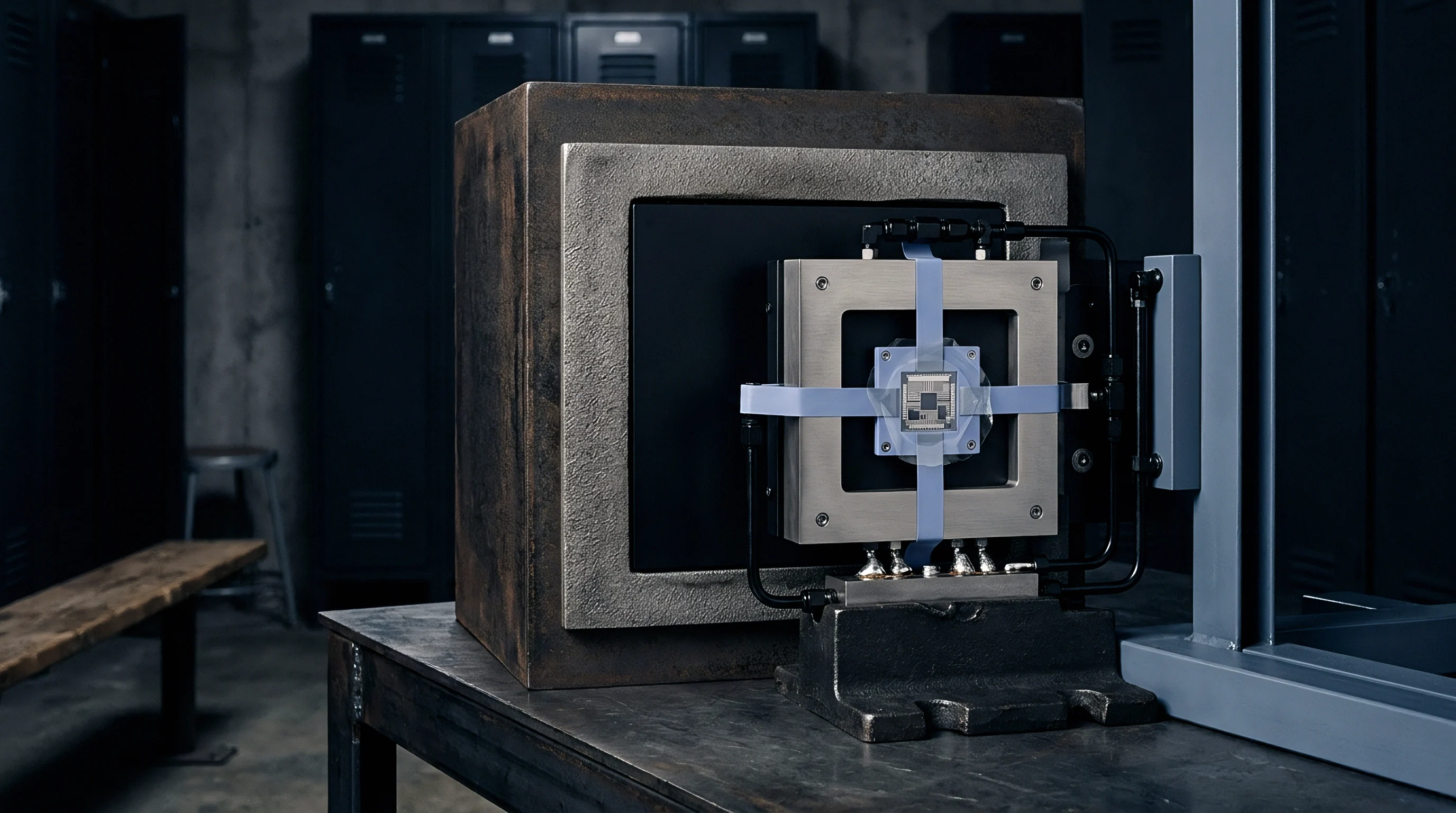
Test enclosures must utilize solid aluminum or copper outer walls to shield the high-impedance signal path from ambient electromagnetic interference and power-line hum. Insulators inside the fixture require non-hygroscopic materials such as virgin PTFE, sapphire, or glass-bonded mica. Connectors must use triaxial configurations where the inner shield carries the guard potential and the outer shield connects to chassis ground.
Air currents inside the chamber must be minimized to prevent electrostatic charge generation across insulating surfaces.
Distinguishing Polarization Memory from Surface Leakage
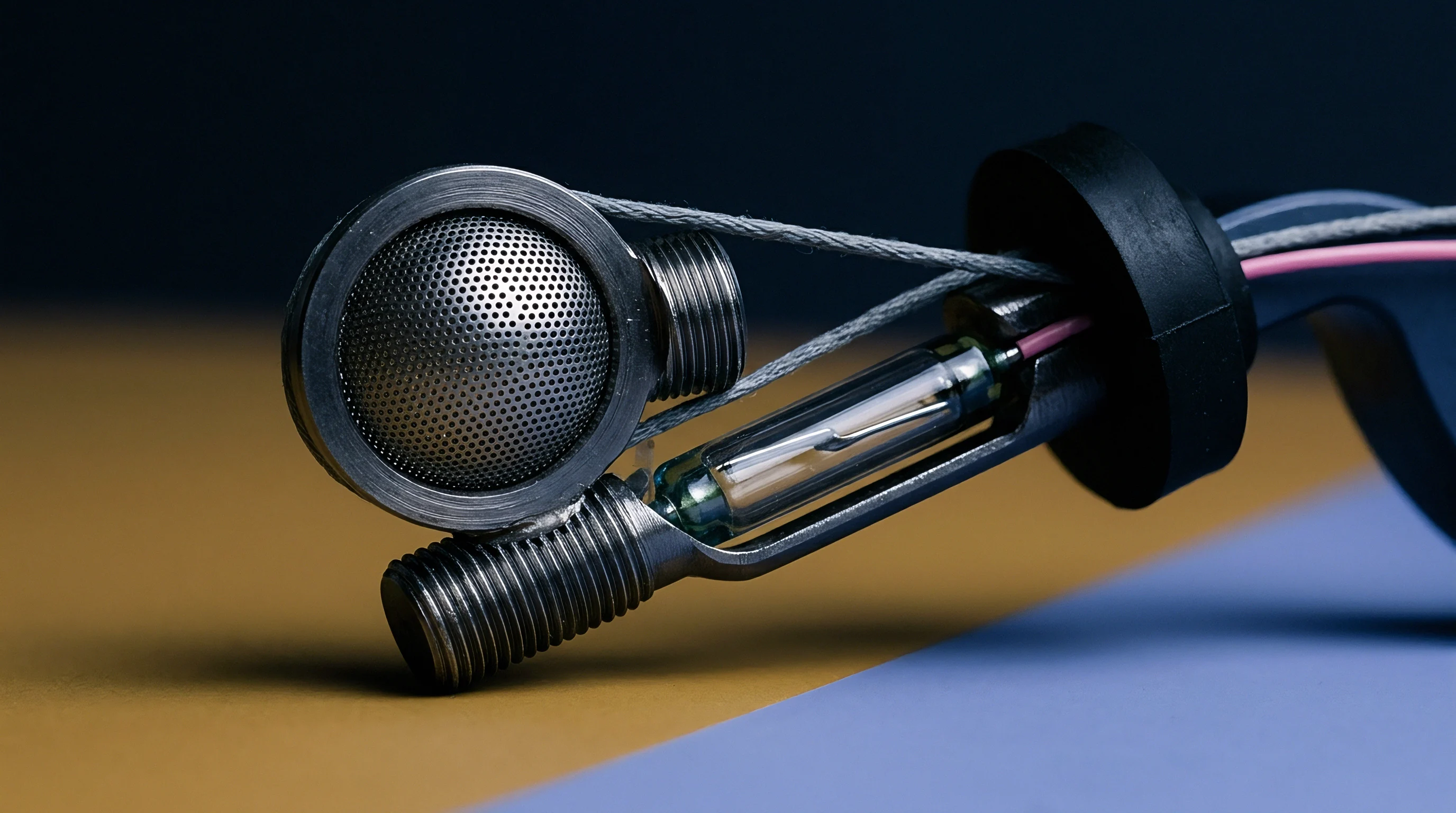
Isolating bulk dielectric absorption from static surface leakage relies on analyzing signal dynamics over time. Static surface leakage current remains constant as long as the applied potential and ambient humidity remain stable. In contrast, dielectric absorption current decays continuously following a power-law or multi-exponential profile.
Applying a step voltage, holding the potential until currents stabilize, and subsequently shorting the input node isolates the discharge current of trapped dipoles. The remaining output current represents pure polarization decay free from static ohmic conduction components.
Compliance with IEC 60601-2-04 safety integration limits mandates baseline residual leakage currents below 50 fA within 60 seconds of step excitation.
Selecting electrometer test fixtures for high-impedance dielectric characterization demands compliance with strict criteria:
- Input Voltage Burden must remain below 20 microvolts across the entire current measurement range to prevent artificial potential gradients across the guard gap.
- Instrument Noise Floor cannot exceed 0.2 femtoamps peak-to-peak within a 0.1 Hz to 10 Hz measurement bandwidth.
- Environmental Chamber Control must maintain temperature stability within 0.1 degrees Celsius and relative humidity within 1.0 percent across 24-hour test cycles.
- Cable Mechanical Restraint must fix all interconnects rigidly to prevent triboelectric charge generation during thermal expansion cycles.
ISO 17025 calibration clauses for high-impedance instrumentation mandate explicit reporting of ambient humidity drift coefficients alongside static accuracy limits.

Ledger
High-performance insulating materials impose direct cost multipliers on board fabrication and assembly procedures. Substrate selection balances electrical polarization stability against physical raw material costs and manufacturing processing complexity. High humidity degrades surface resistance.
Ceramic insulators outperform organic polymers. Temperature alters dipole relaxation rates. Choosing ultra-low-absorption materials such as high-purity alumina or glass-bonded mica increases component piece prices, whereas standard epoxy-glass substrates lower initial build costs while transferring operational expenses to post-assembly software compensation algorithms.
| Substrate Classification | Material Unit Cost Factor | Machining/Tooling Overhead | Second-Source Availability | Absorption Performance Index |
|---|---|---|---|---|
| Standard FR-4 (Tg 150C) | 1.0x | Baseline Standard | Global Multi-Source | Low (High Absorption) |
| High-Tg Halogen-Free FR-4 | 1.3x | Low Overhead | Global Multi-Source | Moderate |
| Polyimide Flex Laminate | 2.5x | Moderate Tooling | Regional Multi-Source | Moderate-Low |
| PTFE-Based Microwave Substrate | 6.0x | Specialized Processing | Limited Manufacturers | High (Very Low Absorption) |
| High-Purity Alumina (Co-Fired) | 15.0x | Extremely High Tooling | Sole to Dual Source | Maximum Stability |
Commercial Substrate Economics and Sourcing Risk
Procuring specialized fluoropolymer or ceramic substrates introduces lead-time risks into high-volume manufacturing pipelines. Few suppliers maintain raw material inventory for low-absorption microwave and electrometer-grade laminates. Lead times for exotic glass-backed PTFE materials often stretch to 26 weeks during supply chain bottlenecks.
Standardizing high-impedance interface designs around widely available high-temperature epoxy formulations backed by aggressive driven guard layouts lowers landed bill-of-materials costs while insulating production lines from single-source raw material shortages.

Specification Requirements for Low-Absorption Substrates
Procurement dossiers for high-impedance interface boards must mandate specific manufacturing and cleaning procedures to enforce low dielectric absorption baseline standards:
Polyimide substrates cost significantly less than high-purity alumina but absorb up to ten times more atmospheric water vapor over extended field exposure.
- Raw Material Lot Traceability links raw laminate rolls directly to factory dielectric absorption test certificates under IPC-TM-650 methods.
- Ionic Contamination Caps limit surface residual ionic species to less than 0.75 micrograms of sodium chloride equivalent per square centimeter prior to conformal coating.
- Bakeout Cycles define mandatory thermal dehydration steps at 120 degrees Celsius for 4 hours preceding protective potting or enclosure sealing.
- Vacuum Solvent Cleaning eliminates hydrophobic mold release agents and soldering fluxes that trap environmental water vapor along trace boundaries.
Choosing low-absorption dielectric materials early in the hardware design phase reduces long-term calibration overhead and eliminates field-retraining expenses.