Multi Frequency Impedance Plane Inversion for Inline Alloy Sorting
Multi-frequency impedance inversion isolates lift-off clearance vectors from conductivity shifts to achieve real-time inline alloy sorting down to 150 microseconds.
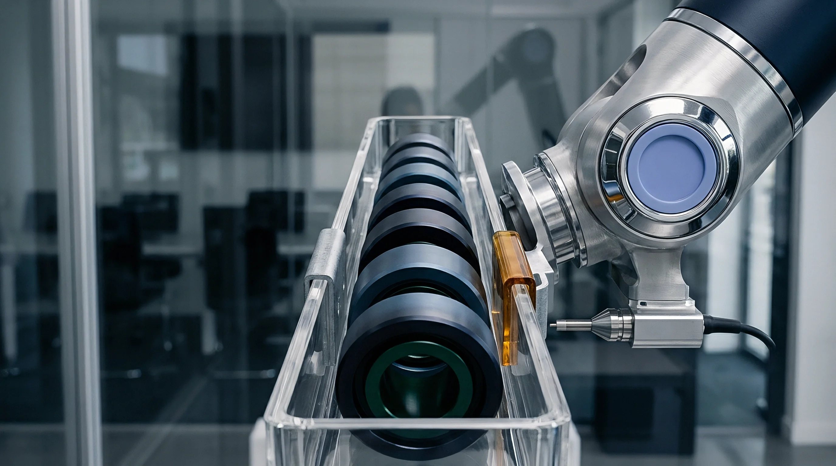

Locus
Sorting non-ferrous and austenitic alloy streams on automated conveyances demands real-time discrimination of subtle differences in electrical conductivity and magnetic permeability. Alternating magnetic fields induced by an primary excitation coil generate secondary eddy currents within the passing metallic stock. These eddy currents produce an opposing magnetic field that alters the complex impedance of the sensor coil.
Plotting resistance against inductive reactance yields an impedance plane trajectory unique to the material electromagnetic profile. Multi-frequency excitation projects this response across multiple skin depths simultaneously, generating a multidimensional signal vector capable of separating bulk material properties from physical geometry.
Skin depth governs penetration. The standard depth of penetration depends inversely on the square root of the excitation frequency, material conductivity, and magnetic permeability. At low frequencies around 1 kilohertz, the electromagnetic field penetrates several millimeters into the bar or tube, capturing core metallurgical structures.
At high frequencies near 1 megahertz, the field concentrates near the outer boundary, reflecting surface conditions, roughness, and localized microstructural cold work. Simultaneous multi-frequency driving currents enable the inversion algorithm to resolve depth-dependent material variations.

Electromagnetic Dispersion across Complex Impedance Trajectories
Each alloy grade traces a distinct locus on the complex impedance plane as excitation frequency varies. High-conductivity materials like 6061-T6 aluminum induce large eddy currents that create substantial inductive phase rotations. Lower conductivity materials like 316L stainless steel generate smaller magnetic counter-fields, keeping the impedance response close to the inductive axis.
By recording the complex impedance vector across four to eight discrete frequencies, the instrumentation system establishes a broad electromagnetic spectral signature. Phase angles shift rapidly.
| Alloy Grade | Conductivity (MS/m) | Relative Permeability | Phase Angle at 10 kHz (deg) | Phase Angle at 100 kHz (deg) | Phase Angle at 1 MHz (deg) |
|---|---|---|---|---|---|
| Aluminum 6061-T6 | 23.2 to 25.0 | 1.0000 | 78.4 | 42.1 | 12.8 |
| Aluminum 7075-T6 | 19.0 to 21.0 | 1.0000 | 81.2 | 48.5 | 16.3 |
| Aluminum 2024-T3 | 17.0 to 19.0 | 1.0000 | 82.9 | 51.8 | 18.5 |
| Stainless Steel 304 | 1.35 to 1.45 | 1.0080 | 88.1 | 82.4 | 61.2 |
| Stainless Steel 316L | 1.25 to 1.35 | 1.0030 | 88.6 | 83.7 | 64.0 |
| Titanium Grade 5 | 0.58 to 0.64 | 1.0001 | 89.3 | 87.1 | 76.9 |
Separating conductivity variations from permeability shifts presents a core mathematical challenge in electromagnetic non-destructive testing. Ferromagnetic alloys introduce magnetic permeability effects that dominate the reactive component of the coil impedance, pulling the signal trajectory along the magnetic locus. Non-ferromagnetic alloys alter the resistive component through pure ohmic dissipation of the induced currents.
Multi-frequency impedance plane inversion uses orthogonal projection matrix transformations to decouple these concurrent physical effects into independent signal channels.
At 100 kilohertz excitation under controlled ambient conditions, Aluminum 6061-T6 produces a phase shift 6.4 degrees wider than Aluminum 7075-T6.

Disentangling Phase Shifts from Surface Clearance Drift
Physical separation between the sensor probe face and the moving alloy surface creates a massive signal vector displacement known as the lift-off effect. Lift-off variations arise from conveyor mechanical vibration, belt bounce, tube eccentricity, and thermal expansion of structural mountings. In single-frequency systems, lift-off amplitude easily swamps the minor conductivity phase differences that differentiate similar alloy chemistries.
Air gaps change impedance.
Multi-frequency inversion maps the lift-off response as a curved trajectory across the complex impedance space. Because the lift-off curve follows a predictable vector path that rotates with excitation frequency, multi-frequency algorithms construct a dynamic baseline surface. Rotating the complex impedance coordinates aligns the lift-off response along one axis, isolating material property variations along the orthogonal axis.
Signal processing hardware applies real-time phase rotation matrices to maintain high alloy separation resolution despite continuous physical clearance fluctuations.
High-frequency channels resolve surface defects while low-frequency vectors penetrate deep into the material core.

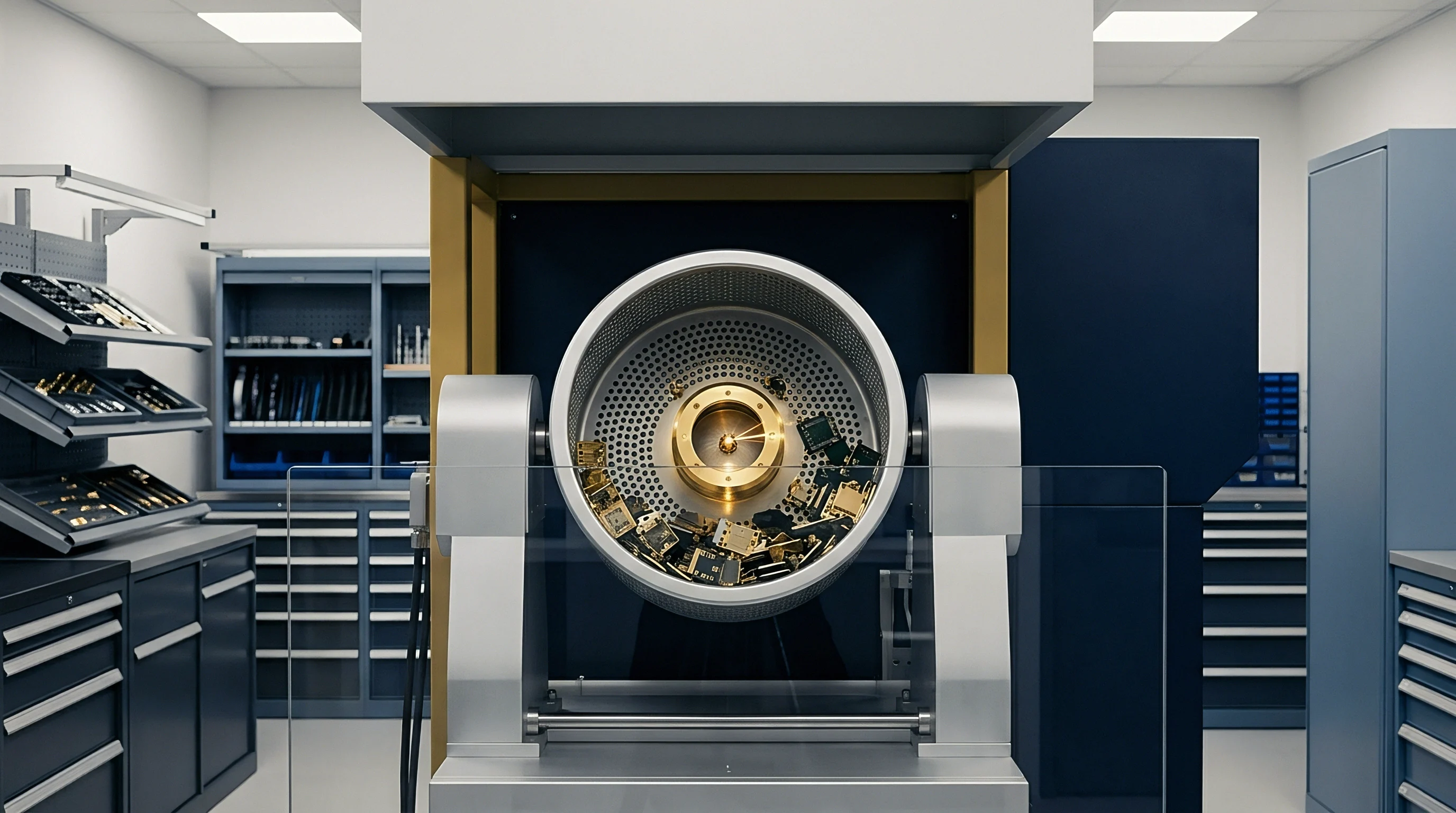
Gap
Air space between the search coil face and the passing metallic work piece alters the mutual inductance of the electromagnetic sensing circuit. As mechanical clearance increases, the magnetic flux coupling efficiency drops exponentially, reducing the magnitude of the induced eddy currents. High-speed sorting lines operating at belt velocities above 3 meters per second generate mechanical turbulence that drives physical clearance variations from 0.5 millimeters to over 4.0 millimeters.
Sensor coils require robust dynamic compensation to maintain signal fidelity under these severe physical conditions.
Mechanical guidance systems attempt to minimize profile bounce, yet geometric variations inside recycled scrap or extruded profiles remain unavoidable. Dynamic coil loading shifts both the real and imaginary components of the measured impedance vector. Signal paths carry high bandwidth.
To prevent false classification, the signal conditioning architecture must track clearance movement across a 50 kilohertz measurement bandwidth without introducing phase distortion or group delay filter artifacts.

Mechanical Flutter and Dynamic Probe Distances
Vibration spectra recorded on high-speed alloy sorting lines display strong mechanical frequencies between 12 Hertz and 450 Hertz caused by drive rollers and conveyor belt splices. These mechanical oscillations manifest as amplitude modulation on the primary carrier signals. Ferrite cores focus flux.
When clearance expands rapidly, the normalized impedance trajectory contracts toward the free-air operating point, masking subtle alloy conductivity transitions.
- Lift off signal saturation occurs when physical clearance exceeds the maximum electromagnetic coupling radius of the probe, driving the demodulated vector into the free-air reference origin.
- Phase axis rotation error develops when dynamic clearance fluctuations occur faster than the phase-locked loop tracking rate, causing lift-off vectors to leak into the conductivity measurement channel.
- Harmonic distortion from tilting happens when passing non-flat sheet scrap tilts relative to the probe plane, generating asymmetric eddy current loops that invalidate isotropic flux assumptions.
- Thermal coil drift shifts the baseline DC resistance of the sensor windings, creating a false impedance origin shift that mimics permanent material conductivity shifts.
Coil geometry directly dictates the depth of field and clearance tolerance envelope. Large diameter encircle coils provide superior spatial averaging for uniform tubular products but lack spatial resolution for irregular scrap fragments. Differential flat surface probes offer tight localized field coupling, though their effective sensing depth remains strictly limited to roughly half the outer coil diameter.
Coil sensitivity drops by more than 60 percent when physical probe clearance exceeds one third of the winding outer diameter.

Transducer Coil Geometry and Primary Field Coupling
Optimizing the primary field geometry demands careful balancing of coil inductance, spatial focus, and resonant frequency. High-inductance coils enhance magnetic field density at low frequencies but restrict the upper frequency boundary due to parasitic winding capacitance. Differential coil configurations utilize two counter-wound sensing elements connected in series opposition.
This differential arrangement cancels common-mode environmental noise, thermal expansion drift, and long-wavelength mechanical clearance shifts.
Absolute coil arrangements utilize a single primary winding paired with an uncoupled reference coil housed within the instrumentation module. While absolute coils deliver superior sensitivity to gradual bulk property changes and conductivity variations, they expose the signal chain to dynamic lift-off distortions. Hybrid probe designs combine differential sensing pick-ups with an absolute primary field driver, enabling simultaneous extraction of localized material structure and absolute bulk conductivity.
Mechanical alignment errors introduced during high-speed passage degrade separation vectors and force good alloy stock into the scrap hopper.


Kernel
Mathematical extraction of physical alloy parameters from multi-frequency impedance data relies on inverting non-linear field equations in real time. Electromagnetic field propagation within a continuous conductive medium obeys the partial differential equations formulated by Dodd and Deeds. Solving these analytical models in the forward direction calculates expected coil impedance for a given conductivity, permeability, sample thickness, and coil distance.
Inline sorting demands the reverse operation: computing unknown conductivity and clearance directly from discretized impedance values recorded at multiple excitation frequencies.
Direct numerical inversion of the forward Dodd and Deeds integral equations requires intense computational effort that exceeds the time budget of real-time sorting gates. Field-programmable gate arrays (FPGAs) execute streamlined inversion algorithms using pre-calculated boundary surfaces, multi-variable polynomial regressions, or specialized neural network lookup spaces. Inversion hardware completes matrix calculations in under 20 microseconds, enabling immediate sorting gate actuation down the line.

Analytical Dodd Deeds Inversion and Lookup Transformations
Modern inversion engines transform raw multi-frequency complex impedance inputs into distinct physical state coordinates. The inversion kernel projects the measured vector against a multi-dimensional surface grid constructed during calibration across known alloy standards. Boundary transformation matrices correct for non-linear flux distribution shifts across high conductivity boundaries.
Raw signals demand filtering.
- Demodulate in-phase and quadrature current signals across all active drive frequencies using direct digital synthesis clocks.
- Subtract the uncoupled free-air impedance vector from each frequency channel to isolate material-induced complex voltage changes.
- Apply temperature-compensated gain scaling factors to normalize signal amplitudes across varying environmental conditions.
- Multiply the normalized complex impedance vector by the pre-computed two-dimensional unmixing matrix to separate lift-off from conductivity.
- Interpolate the isolated conductivity parameter against the calibrated alloy boundary table to generate a real-time chemical grade assignment.

Does Parallel Demodulation Eliminate Processing Latency?
Simultaneous drive signals composed of multi-frequency frequency-division multiplexed (FDM) sine waves pass into the primary driver amplifier. The sensing channel digitizes the composite return voltage using a high-speed, 16-bit analog-to-digital converter operating at sample rates above 10 megasamples per second. Parallel digital signal processing streams isolate individual frequency components using digital phase-sensitive demodulation algorithms executed within FPGA logic blocks.
Digital demodulation multiplies the incoming digitized signal stream by synchronous sine and cosine reference signals generated by internal direct digital synthesis registers. Low-pass finite impulse response (FIR) filters remove double-frequency mixing products, yielding pristine in-phase and quadrature voltage values for each driver frequency. Parallel signal pipelines execute these demodulation loops concurrently, eliminating the sequential multiplexing delays that restrict traditional single-frequency instruments.
Digitizers introduce phase lag. Lookup tables accelerate inversion.
System latency from initial coil excitation to gate output actuation remains below 150 microseconds across high-speed parallel DSP architectures.
The exact mathematical point where non-linear thermal gradients override multi-frequency phase rotation remains open for continuous high-speed extrusion lines.


Margin
Alloy sorting success hinges on establishing non-overlapping acceptance windows within the inverted conductivity-permeability decision plane. Commercial aluminum formulations frequently feature overlapping conductivity specification bands caused by variations in trace alloying elements and temper treatments. For instance, high-conductivity heat-treated 6063 aluminum can overlap with lower-bound conductivity ranges of cast 356 alloys.
Precision sorting requires narrow decision margins supported by tightly controlled noise floors throughout the analog signal acquisition hardware.
Thermal stability dictates long-term sorting boundary accuracy. Extrusion and scrap processing facilities experience ambient air temperature swings exceeding 30 degrees Celsius over a single operational shift. Because metallic electrical conductivity changes at roughly 0.4 percent per degree Celsius, uncompensated temperature shifts easily shift a 6061 alloy vector into a 6063 sorting decision domain.
System calibrations require continuous temperature monitoring paired with automated mathematical offset drift corrections.

Conductivity Overlap and Temperature Compensation Limits
Thermal sensors embedded inside the probe assembly track coil assembly temperature, while infrared pyrometers measure incoming alloy surface temperatures. Mathematical compensation kernels apply linear temperature correction coefficients to calculated conductivity values prior to grade classification. Scrap rates drive cost.
Thermal shifts alter readings.
| Signal Stage | Target Parameter | Acceptable Noise Floor | Operating Bandwidth | Cross-Sensitivity Threshold |
|---|---|---|---|---|
| Analog Front End | Differential Voltage | 1.2 nV/sqrt(Hz) | DC to 2 MHz | -85 dB Channel Isolation |
| ADC Converter | Quantization Error | 88 dB SNR (16-Bit) | 10 MSPS Nyquist | 0.5 LSB Integral Non-Linearity |
| DSP Demodulator | Phase Quadrature | 0.01 Degree Phase Error | 50 kHz FIR Stopband | -90 dB Harmonic Rejection |
| Inversion Kernel | Conductivity Accuracy | 0.05 MS/m Resolution | 100 kHz Refresh Rate | 0.02 MS/m per mm Lift-Off Drift |
Signal-to-noise ratio within the analog front end imposes a hard physical ceiling on sorting accuracy. Preamplifiers operating near conductive sorting lines encounter extreme electromagnetic interference from variable frequency drives, heavy motor contactors, and wireless industrial networks. Differential line drivers, double-shielded twisted-pair cables, and active analog bandpass filtering maintain signal integrity before digitization.
According to ISO 21968, eddy current conductivity instruments must maintain measurement uncertainty within plus or minus 0.5 percent of reading across the full operational temperature range.

Boundary Verification and Sorting Window Tolerances
Establishing reliable decision boundaries requires statistical analysis of production alloy lots across multiple heat numbers and processing batches. Decision boundaries defined by tight Gaussian distribution curves minimize misclassification risks, ensuring pure metal fractions at the sorter outlet hoppers.
- Conductivity baseline calibration uses primary physical reference standards certified to national metrology laboratory traces at 20 degrees Celsius.
- Lift-off envelope verification tests inversion tracking accuracy across step-gauge spacers from 0.0 mm to 5.0 mm in 0.5 mm increments.
- Thermal drift verification subjects the sensor head to controlled thermal cycling inside an environmental chamber while reading static alloy targets.
- Noise immunity audit monitors baseline phase jitter while surrounding industrial machinery operates under maximum electrical load conditions.
Transducer manufacturers frequently claim ambient drift falls within standard calibration limits when uncompensated coil heating distorts phase measurements.


Contract
Integrating multi-frequency impedance plane inversion systems into industrial sorting infrastructure requires careful evaluation of technical specifications, hardware intellectual property, and system support commitments. Sensor module procurement involves selecting between turnkey sorting subsystems and custom OEM sensing engines designed for deep integration into proprietary machinery. Buyers must verify transducer physical robustness, IP67 ingress protection, and resistance to aggressive industrial oils and mechanical abrasion.
Procurement documents must specify exact measurement performance metrics under operational inline conditions rather than static laboratory conditions. Datasheet specifications recorded at static zero-clearance conditions provide little indication of dynamic sorting accuracy on high-speed conveyors. Technical tenders should mandate full disclosure of phase accuracy, signal acquisition latency, and maximum dynamic lift-off compensation ranges.

Commercial Sensor Architectures and Intellectual Property Sourcing
Proprietary inversion algorithms often arrive locked inside OEM FPGA microcode, limiting end-user modification and custom alloy boundary mapping. Open architectural models provide raw complex impedance output streams via high-speed industrial Ethernet interfaces like EtherCAT or PROFINET, allowing integrators to execute custom inversion kernels on external edge processors. Extrusion lines run fast.
Multi-frequency instrumentation systems command unit prices ranging from 8,000 USD for basic two-frequency OEM driver boards to over 45,000 USD for ruggedized multi-channel inline systems complete with automated thermal compensation and high-speed sorting gate controllers. System integrators must evaluate total cost of ownership including spare probe availability, factory recalibration requirements, and long-term firmware support windows.

System Integration and Ingestion Protocol Commitments
Digital interface protocols dictate system response times and real-time sorting performance. Fieldbus hardware must support cyclic data transmission rates of 1 millisecond or faster to ensure sorting gate actuators receive trigger commands before moving scrap fragments pass the rejection point. Mill certificates verify chemistry.
Adherence to EN 10204 inspection certificate type 3.1 shifts liability back to the mill when chemical re-testing invalidates inline sorting data.