Designing Thermal Soak Chambers for Inertial Sensor Allan Variance Characterization
Precision Allan variance characterization demands thermal soak chambers featuring sub-millikelvin temperature stability, low vibration, and zero fluid turbulence.

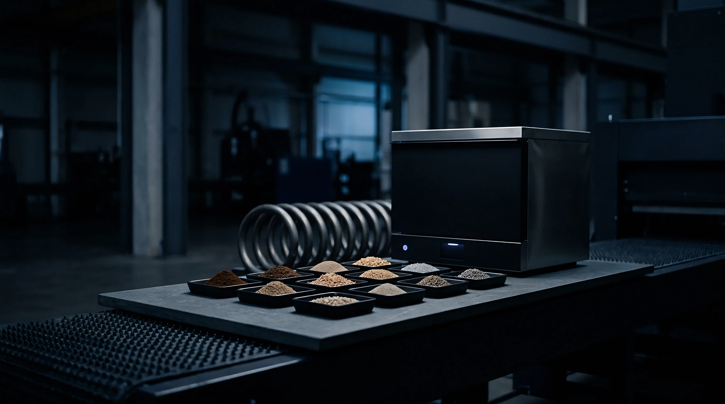
Vault
Characterizing inertial sensors requires far more environmental isolation than standard industrial thermal chambers can provide. Commercial units cycling at two degrees Celsius per minute create spatial temperature imbalances throughout the internal envelope. During Allan variance evaluations of navigation-grade micro-electromechanical systems or tactical fiber optic gyroscopes, thermal oscillations above fifty millikelvin obscure the underlying sensor noise floor.
The mechanical housing surrounding the device under test acts as the primary barrier against ambient perturbations, thermal drift, and external acoustic coupling.
Heavy thermal mass construction dampens high-frequency environmental ripple before it reaches the sensor housing. Placing thick oxygen-free high-conductivity copper or cast aluminum alloy plates inside an insulated shell creates a passive low-pass thermal filter. These conductive walls store thermal energy, smoothing out rapid switching transients from thermoelectric coolers or heating elements.
Selecting low-emissivity inner coatings, such as polished gold plating or bare mirror-finish aluminum, limits radiative heat transfer between chamber walls and the sensor chassis, steering thermal exchange through predictable conductive paths.
Vacuum insulation panels sandwiched between stainless steel skins deliver far better steady-state isolation than polyurethane foam or rockwool. This setup limits boundary layer heat loss to less than five watts per square meter at a sixty degree Celsius delta. Minimizing cabinet losses lets the temperature control loop run at lower drive currents, which reduces electromagnetic interference from switching power supplies on sensitive analog signal traces.
| Material Configuration | Thermal Conductivity (W/m·K) | Specific Heat Capacity (J/kg·K) | Thermal Time Constant Scale (Hours) | Spatial Uniformity Impact |
|---|---|---|---|---|
| Oxygen-Free Copper Assembly (20 mm) | 391.0 | 385 | 1.2 to 2.5 | Sub-millikelvin local variance |
| Cast Aluminum 6061-T6 Buffer (15 mm) | 167.0 | 896 | 0.8 to 1.8 | Under 10 millikelvin gradient |
| Vacuum Panel Insulation Shell (25 mm) | 0.004 | 800 | 8.0 to 15.0 | Suppresses ambient room fluctuations |
| Austenitic Stainless Steel Outer Frame | 16.0 | 500 | 0.3 to 0.7 | Structural rigidity, high thermal mass |

Thermal Inertia and Radiant Barrier Architecture
Radiant energy transfer becomes a primary source of measurement error whenever wall temperatures shift relative to the internal sensor fixture. Enclosing the main test stage inside a secondary polished copper shield decouples the device under test from outer wall fluctuations. Radiative heat transfer dominates inside vacuum chambers.
Painting the outer housing of the device under test with a high-emissivity black coating and surrounding it with a gold-plated radiative shield establishes a uniform radiative environment. This locks the sensor frame to the controlled shield temperature rather than the fluctuating surface of the heat exchanger.
At a constant ambient soak temperature of 25 degrees Celsius, a 100-millikelvin amplitude wall thermal ripple produces an artificial bias drift peak in tactical accelerometers at tau equal to 1000 seconds.
Structural fasteners extending from the outer frame to the inner thermal mass serve as thermal bridges. Standoffs made of nylon, polyether ether ketone, or ceramic isolate the inner cold plate from enclosure vibrations and thermal leaks. Calculating mechanical shear loads during sensor mounting determines the minimum cross-sectional area needed for these isolation standoffs, maximizing thermal resistance while maintaining structural stability.

Decoupling External Ambient Temperature Cycles
HVAC systems in laboratory environments typically cycle room temperatures by one to three degrees Celsius over periods of fifteen to forty-five minutes. Unbuffered thermal chambers pass these low-frequency cycles directly to the sensor under test, generating false slope signatures on Allan deviation plots at long correlation times. Increasing the inner enclosure mass delays thermal transfer, pushing periodic room disturbances to the far right of the correlation spectrum, well outside the target tau band.
Mounting the entire soak assembly inside a secondary outer climate shield further dampens ambient room swings. A dual-shell arrangement holds the intermediate air gap within a narrow two-degree band using auxiliary thermoelectric plates. This secondary system absorbs eighty percent of external room swings, letting the primary internal control loop run within an ultra-quiet thermal region.
Otherwise, thermal isolation breakdowns produce artificial bias instability figures that can cause compliant sensors to fail qualification testing.


Plenum
Forced fluid circulation involves a clear trade-off in inertial sensor test engineering. Moving air over heating and cooling coils enables rapid thermal response during temperature ramps. However, high air velocities create turbulent pressure fluctuations across the sensor diaphragm or optical frame, introducing acoustic noise and physical micro-vibrations.
Micro-turbulent convection around sensor packages causes localized density shifts, disturbing thermal boundary layers unpredictably and corrupting long-term bias characterization.
An effective fluid channel must convert turbulent fan discharge into uniform, low-velocity laminar flow before air enters the sensor soak volume. Flow straighteners built from honeycomb structures or fine stainless steel wire mesh homogenize fluid velocity. Keeping air speed below 0.5 meters per second maintains effective convective heat transfer while suppressing micro-pressure noise against the sensor fixture frame.
- Micro-turbulent convective noise generates localized thermal gradients across the MEMS die substrate, causing localized strain variations that show up as false bias instability on Allan variance curves.
- Acoustic pressure oscillations from high-RPM circulation impellers couple directly into accelerometer proof masses, inducing non-gravitational rectification offsets.
- Spatial temperature gradients across un-mixed fluid streams create distinct thermal zones within the soak volume, preventing simultaneous multi-axis sensor calibration.
- Recirculation dead zones trap heat generated by internal sensor power dissipation, causing localized device self-heating that offsets the controlled ambient temperature baseline.

Laminar Distribution and Micro Turbulence Control
Controlling fluid motion inside the conditioning volume requires precise duct geometry and flow baffling. A widening diffuser duct positioned directly downstream of the circulation fan slows high-velocity air, converting kinetic energy into static pressure. Expansion angles over seven degrees induce flow separation along duct walls, creating large eddy currents.
Keeping expansion angles below six degrees preserves smooth boundary layers and avoids localized pressure drops.
Standard test specifications mandate that spatial thermal variation across the sensor housing volume shall not exceed 20 millikelvin under steady-state soak conditions.
Placing stainless steel mesh screens in series across the plenum cross-section breaks down large turbulent vortices. The chosen wire diameter and mesh density dictate pressure drop and flow-smoothing efficiency. Downstream of the final mesh screen, the fluid velocity profile flattens into a predictable laminar front, delivering uniform convective heat exchange across the sensor fixture without localized hot spots.

Conductive Heat Sinks versus Circulated Gas
Turning off fluid circulation completely during Allan variance data collection offers major noise benefits. A conductive soak chamber relies on solid-state heat transfer, clamping the sensor chassis directly to a liquid-cooled or Peltier-driven copper cold plate. Direct mechanical contact replaces fluid convection, eliminating pressure noise and airflow-driven thermal fluctuations entirely.
Solid-state conduction relies on flat, precision-ground interface surfaces to eliminate microscopic air gaps. Thermal interface materials like graphite sheets or filled silicone pads lower contact resistance. However, applying too much interface material increases mechanical compliance, introducing drift under thermal expansion.
Clamping torque must be tightly set using calibrated torque wrenches to ensure reproducible joint conductance without distorting the internal optical or mechanical alignment of the inertial sensor. A thermal design relying solely on forced air inevitably introduces flow noise into long-term gyro data.


Mount
Mechanical vibration transmitted into the sensor under test introduces physical acceleration signals that corrupt Allan variance plots. Blower fans, fluid pumps, and external laboratory movement generate structural vibrations ranging from tens of Hertz to several kilohertz. Accelerometers detect these signals directly as motion, while gyroscopes register them through structural rectification and vibration-to-bias cross-sensitivity mechanisms.
A thermal test chamber must provide high acoustic and mechanical attenuation across all axes.
Low-frequency isolation systems prevent floor vibrations from reaching the internal soak platform. Soft elastomeric mounts or tuned air springs isolate the test rig from building movement. Selecting an isolation system requires balancing soft mechanical compliance against structural rigidity.
Excessively soft suspension allows the chamber to tilt or sway, generating false angular rate or gravity-vector change signals during long characterization runs.

Acoustic Attenuation and Structural Isolation
Airborne sound waves generated by chamber refrigeration compressors and fans strike the exterior fixture walls, transforming into structural vibrations. Heavy elastomeric damping sheets applied to outer metal panels reduce cabinet resonance. Sound attenuation materials installed within interior duct walls absorb high-frequency acoustic energy before it enters the primary soak area.
Decoupling fan assemblies from the main chamber frame prevents motor vibrations from traveling down structural members. Flexible silicone or fluorosilicone bellows connect fluid ducts across structural breaks, isolating mechanical vibration while retaining thermal fluid containment. Fan motors generate low-frequency vibration.
Installing motors on tuned elastomer mounts targets specific motor rotation frequencies, reducing transmitted vibrational energy by more than twenty-five decibels.

Suspension Mechanics for Micro Vibration Rejection
Designing internal suspension mechanics involves matching the system natural frequency to the quietest band of the ambient noise floor. Passive multi-stage spring damper systems lower the structural resonant frequency below five Hertz. At frequencies above seven Hertz, isolation efficiency increases rapidly, attenuating ambient laboratory floor motion before it reaches the sensor mounting plate.
Sensing elements with high sensitivity demand active or passive damping to prevent resonance amplification at low frequencies. Silicone fluid dampers or eddy-current magnetic dampers suppress suspension ring-down without introducing mechanical friction or hysteresis. Damping ratios tuned between 0.6 and 0.7 of critical damping optimize transient settling time while preserving high-frequency isolation performance.
Equipment manufacturers often cite internal isolation ratings, yet fan motor bearings degrade over time, transmitting uncalibrated vibrational spikes directly into the sensor plate.


Telemetry
Measuring thermal behavior inside the soak volume requires instrumentation capable of micro-kelvin resolution and long-term calibration stability. Standard industrial thermocouples lack the precision and low drift needed to track sub-millikelvin thermal shifts across multi-day Allan variance runs. Platinum resistance thermometers and ultra-stable precision thermistors represent the standard choice for reference temperature tracking inside high-performance soak chambers.
Self-heating in reference temperature sensors corrupts absolute readings if drive currents are set too high. For example, passing a one-milliamp excitation current through a 100-ohm platinum element generates enough heat to raise the element temperature above the surrounding medium. Reducing excitation current below one hundred microamps keeps self-heating errors at sub-millikelvin levels.
High-precision analog-to-digital converters reading thermistor bridges require low-noise current sources and stable voltage references so electronic drift is not mistaken for actual chamber temperature movement.

Which Thermal Gradients Disconnect Allan Variance Drift Figures?
Temperature differentials across a sensor housing drive mechanical strain variations across internal silicon bridges or optical frames. When a spatial gradient forms between the top and bottom of a MEMS gyroscope chassis, thermal expansion flexes the package, creating an artificial rate signal. Tracking these gradients requires installing multi-point temperature sensor arrays directly on the device under test fixture.
| Sensor Type | Sensitivity / Output Scale | 100-Hour Drift Stability | Self-Heating Exposure | Noise Density (mK/√Hz) |
|---|---|---|---|---|
| Pt100 Thin-Film RTD (Class A) | 0.385 Ω/°C | Under 10 mK | Moderate (Requires I < 100 µA) | 0.05 |
| NTC Thermistor (10 kΩ @ 25°C) | ~4% / °C resistance change | Under 2 mK | Low (High base resistance) | 0.005 |
| Pt1000 Wire-Wound Element | 3.85 Ω/°C | Under 5 mK | Low (Higher resistance reduces current) | 0.02 |
| Integrated Semiconductor IC | Digital 16-Bit output | 20 to 50 mK | High (Internal active circuitry) | 0.50 |
Consider a sensor qualification run where a thermistor array monitors fixture temperature stability. If a MEMS accelerometer has a temperature coefficient of offset of 1.5 milligals per degree Celsius, and the chamber conditioning loop exhibits a sinusoidal thermal drift of 10 millikelvin peak-to-peak over a two-hour period, the resulting artificial bias shift equals 0.015 milligals. Evaluating Allan variance at tau equal to 3600 seconds maps this 0.015 milligal artificial shift directly onto the velocity random walk and bias instability curves.
Separating true sensor bias drift from chamber-induced thermal wave corruption requires recording fixture thermal telemetry synchronously with sensor output data.
Synchronizing temperature acquisition clocks with the inertial sensor data acquisition unit eliminates phase jitter in thermal compensation algorithms. Sampling reference sensors at identical timestamps enables cross-correlation analysis, revealing exact thermal time constants between chamber air, mounting fixture, and the internal sensor die.
Validating telemetry signal integrity requires adhering to documented data collection standards:
- Shielded twisted-pair cabling must isolate low-level analog RTD signals from high-current Peltier driver lines to prevent magnetic switching noise coupling.
- Four-wire Kelvin connections must eliminate lead wire resistance variations caused by temperature changes along the cabling path inside the chamber.
- Excitation current reversal must cancel thermal electromotive force offsets generated across dissimilar metal junctions in the measurement loop.
- 24-bit delta-sigma ADCs must employ low-drift voltage references featuring temperature coefficients below 0.5 ppm per degree Celsius.
A rule of thumb dictates that temperature measurement noise must sit at least one order of magnitude below the expected thermal sensitivity threshold of the device under test.
Will future multi-axis sensor arrays require optical fiber Bragg grating sensors embedded directly inside the package to eliminate metal lead heat conduction entirely?


Variance
Allan variance analysis characterizes noise processes in precision inertial instruments as a function of averaging time tau. The standard plot reveals quantization noise, angle random walk, bias instability, rate random walk, and rate ramp signatures. Non-stationary thermal conditions inside the soak chamber introduce deterministic drift patterns that corrupt these noise slopes, shifting calculated bias instability thresholds upward.
Thermal stability during the soak period determines whether Allan variance curves represent true sensor noise floors or environmental chamber artifacts. When a thermal chamber cycles up and down, the resulting temperature derivative drives non-linear sensor responses. Reaching a true flat bias instability floor requires keeping chamber drift rates below five millikelvin per hour across test intervals exceeding one hundred hours.

Separating Sensor Drift Floor from Environmental Thermal Ripple
Distinguishing environmental thermal noise from internal sensor flicker noise depends on analyzing tau slope trends. White noise characteristics display a negative one-half slope on log-log Allan deviation plots, whereas flicker bias noise presents a flat zero slope. Thermal oscillations inside the chamber create a distinctive peak or bump on the curve at tau values corresponding to half the thermal cycle period.
Applying cross-correlation filtering between external thermistor telemetry and sensor output data allows mathematical subtraction of thermal drift components. Post-processing algorithms model the thermal transfer function between fixture thermocouples and internal sensing dies. Subtracting predicted thermal bias shifts restores the natural noise slope, revealing the underlying sensor performance ceiling uncorrupted by chamber dynamics.

Long Term Soak Duration Requirements under IEEE Standards
Testing navigation-grade inertial sensors follows procedures established in industry standards. IEEE Std 952 and IEEE Std 1554 outline standard methodology for single-axis fiber optic gyroscopes and accelerometers, mandating extended thermal soak periods to ensure the device reaches total thermal equilibrium before valid Allan variance logging begins.
- Mount the inertial sensor unit on the isolated thermal chamber cold plate, tightening torque-controlled fasteners to standard specification.
- Connect four-wire temperature telemetry sensors directly to the sensor housing baseplate and surrounding chamber air volume.
- Ramp the soak chamber to the target test temperature at a controlled rate not exceeding one degree Celsius per minute.
- Maintain the target temperature soak for a minimum of four thermal time constants to ensure internal package thermal equilibrium.
- Initiate continuous sensor data logging and synchronized temperature telemetry capture for a minimum duration of seventy-two hours.
- Process collected time-series data using overlapping Allan variance calculations, applying thermal cross-correlation corrections where required.
IEEE Std 1554 Clause 7.3 specifies that environmental conditions during long-term bias characterization shall remain constant such that parameter variation due to test environment fluctuations is negligible compared to the sensor intrinsic noise.
Compliance with standard testing specifications ensures that Allan variance metrics calculated across different laboratories remain directly comparable. Deviating from strict thermal stabilization times introduces transient thermal errors that can invalidate qualification dossiers submitted to aerospace and defense contractors.


Outlay
Procuring or building a high-stability thermal soak chamber involves balancing custom performance engineering against off-the-shelf system availability. Commercial environmental chambers purchased from commercial vendors often feature rapid cooling rates and wide operating ranges, but they lack the micro-kelvin stability, acoustic isolation, and low-vibration architecture required for navigation-grade Allan variance testing without extensive modification.
Custom chamber builds allow direct integration of heavy thermal masses, quiet thermoelectric drivers, and passive isolation mounts tailored specifically to inertial testing requirements. Building custom equipment increases upfront non-recurring engineering costs and requires internal mechanical, thermal, and signal processing expertise. The choice hinges on whether testing volume justifies dedicated custom architecture or whether modified commercial chambers meet baseline targets.

Custom Chamber Engineering against Commercial off the Shelf Units
Commercial chambers rely on compressor-based refrigeration systems that generate significant physical vibration and thermal hysteresis. Retrofitting a commercial chamber involves installing secondary internal thermal soak boxes, replacing stock fan controllers with low-noise DC blowers, and routing isolated sensor power lines through custom vacuum feedthroughs. These modifications add cost and complexity while voiding OEM warranties.
Building a custom chamber centered around H-bridge-driven Peltier modules provides precise solid-state control without moving parts in the primary thermal loop. Thermoelectric coolers offer rapid directional heat pumping and continuous linear modulation, eliminating switching spikes inherent to mechanical compressors. Custom TEC drivers, however, often involve long lead times.
| Subsystem Component | Primary Technology Selection | Vendor Base Availability | Average Lead Time (Weeks) | Single Source Vulnerability Risk |
|---|---|---|---|---|
| Ultra-Low Drift TEC H-Bridge Controller | Analog Linear / Low-EMI PWM | Limited specialist suppliers | 12 to 18 | High (Custom firmware dependence) |
| Precision Temperature Reference ADCs | 24-Bit Delta-Sigma / Low Drift Ref | Multiple global semiconductor vendors | 4 to 8 | Low (Standard footprint alternatives) |
| Low-Emissivity Polished Gold Shields | Electroplated Copper Substrates | Regional precision platers | 3 to 6 | Moderate (Quality plating variation) |
| Multi-Stage Passive Vibration Mounts | Tuned Elastomer / Air Isolation | Established industrial vendors | 6 to 10 | Low (Multiple equivalent suppliers) |

Component Sourcing and Sole Source Driver Risks
Sourcing specialized linear power supplies and high-resolution temperature controllers exposes chamber engineering projects to single-source supply risks. High-power linear drivers that switch TEC polarity without generating harmonic noise rely on specialized power semiconductors with narrow supplier bases. Identifying alternative sources during design helps prevent delays when specialized parts enter allocation.
Selecting standard, widely produced digital sensing components and open control platforms lowers long-term maintenance costs and simplifies system replication across multiple test stations. Custom thermal soak chambers designed around non-proprietary control loops allow straightforward recalibration and software updates over decade-long operational lifespans, meeting the sub-millikelvin stability demands of silicon sensors.
Investing in modular chamber architecture permits incremental upgrades as sensor performance targets scale upward. Interchangeable inner cold plates accommodate evolving package footprints, while upgraded secondary insulation shells extend thermal performance without requiring a complete overhaul of the primary thermal control electronics and software stack.