Quantifying Zero Return Drift across Environmental Temperature Cycles
Zero return drift quantifies permanent baseline offset shifts caused by thermo-mechanical stress relaxation after sensors undergo environmental temperature cycling.


Foil
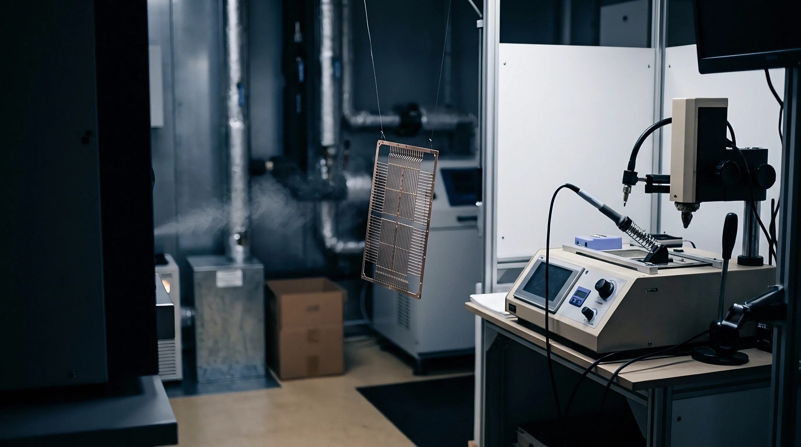
Thermo-Mechanical Yield in Substrate Interfaces
Precision strain elements subjected to thermal swings exhibit measurable offset shifts upon returning to baseline temperatures. When a transducer moves from ambient conditions through severe thermal extremes and back to twenty degrees Celsius, internal structural stresses do not resolve along identical pathways. Metallic strain grids, ceramic diaphragms, and piezoresistive silicon chips bond to structural substrates through adhesives, glass fits, or metallic braze layers.
Differential coefficients of thermal expansion generate micro-scale shear stresses across these joints during temperature transitions.
Zero point instability compromises long readings. Micro-yield events within the adhesive matrix or grain boundary slips within the resistive foil permanently alter the un-energized bridge balance. Elastic memory degrades over consecutive thermal spans.
A transducer trimmed to output exactly zero millivolts at twenty degrees Celsius can exhibit a residual offset of zero point zero five percent to zero point three percent of full scale span following a single thermal excursion to eighty-five degrees Celsius.
Adhesive layer viscoelastic creep permanently alters Wheatstone bridge balance following exposure to elevated thermal limits.

Microstructural Relaxation and Phase Evolution
Material mismatch generates internal shear. Constant thermal flexing forces polymeric adhesives past their glass transition temperatures, initiating localized creep and chain reorientation. Sputtered thin-film sensors bonded directly to metallic diaphragms avoid organic adhesives but remain vulnerable to residual stress relief within the metallic crystal lattice itself.
Annealing effects occurring at upper temperature limits alter the electrical resistivity of nickel-chromium or platinum-palladium alloys, leaving a permanent resistance delta when cooled.
Moisture desorption and absorption during thermal cycling add secondary drift vectors. Polyimide substrates absorb atmospheric humidity, expanding their dimensional profiles and imposing mechanical strain onto the etched grid. High-temperature excursions drive out entrapped moisture, shrinking the substrate and shifting the un-loaded output.
When the sensor returns to reference ambient conditions, re-hydration occurs over hours or days, creating a time-dependent zero return drift that hides behind thermal stabilization measurements.
Failure to isolate structural micro-yield from true thermal coefficients leads to erroneous compensation matrix design. Linear temperature compensation resistors correct for predictable slope changes during temperature excursions, yet remain incapable of canceling permanent baseline offsets caused by mechanical hysteresis. Operating a sensor system under unquantified zero shift conditions results in cumulative tare errors, invalidating long-term monitoring data across seasonal weather changes.

Cycling
Thermal Rate Effects and Temperature Gradients
Evaluating transducer response requires controlled exposure across specified operating temperature bands. Transient thermal gradients across the sensor body generate false offset values that must settle before true zero return drift can be quantified. Rapid temperature transition rates induce thermal shocks, expanding outer housing walls while core sensing elements lag behind in thermal equilibrium.
Thermal ramp rates dictate microstructural yield. A transition rate of ten degrees Celsius per minute induces significant internal temperature differentials, generating transient shear stresses far higher than those produced during a slow ramp of one degree Celsius per minute. Testing protocols must define transition speed, dwell duration at extreme limits, and total cycle count to deliver reproducible metrological data.
Transducers cycled between negative forty degrees Celsius and eighty-five degrees Celsius exhibit zero return drift within zero point zero two percent of full scale span when dwell periods exceed two hours.

Standardized Transducer Technology Comparison
Different sensing technologies exhibit distinct levels of zero return drift when subjected to identical environmental temperature profiles. Selection of sensor architecture dictates baseline stability limits over multi-year operational cycles.
| Transducer Technology | Primary Drift Mechanism | Mean Zero Drift (% FSO) | Maximum Deviation (% FSO) | Recovery Dwell Time (Hours) |
|---|---|---|---|---|
| Bonded Metal Foil Strain Gauge | Adhesive matrix micro-creep and substrate hygro-expansion | 0.085 | 0.140 | 24.0 |
| Sputtered Thin-Film Metal Matrix | Lattice stress relaxation and metallization annealing | 0.012 | 0.025 | 2.0 |
| Piezoresistive Silicon (MEMS) | Packaging stress relaxation and glass frit shear | 0.045 | 0.090 | 6.0 |
| Quartz Crystal Resonator | Internal mounting structure stress and crystal ring shear | 0.003 | 0.008 | 0.5 |
| Variable Capacitance Ceramic | Diaphragm edge seal hysteresis and ceramic micro-yield | 0.020 | 0.040 | 4.0 |

Profile Execution for Baseline Drift Verification
Accurate quantification of zero return drift follows a strict environmental profile structure. Skipping soak intervals or shortening measurement windows disguises long-term offset shifts as transient thermal lag.
- Stabilize the device under test at twenty degrees Celsius reference baseline for four hours while monitoring excitation voltage stability within zero point zero zero one percent.
- Record initial un-loaded zero output voltage, taking one hundred readings over sixty seconds to establish the statistical baseline average.
- Ramp the environmental chamber ambient temperature to eighty-five degrees Celsius at a constant rate of one degree Celsius per minute.
- Dwell at eighty-five degrees Celsius for three hours, allowing internal mechanical components to achieve complete thermal stabilization.
- Ramp the chamber ambient temperature down to negative forty degrees Celsius at one degree Celsius per minute.
- Dwell at negative forty degrees Celsius for three hours to allow structural stress stabilization under sub-zero conditions.
- Return the chamber ambient temperature to twenty degrees Celsius reference baseline at one degree Celsius per minute.
- Dwell at twenty degrees Celsius for twenty-four hours while continuously recording un-loaded output voltage to map moisture re-absorption and structural relaxation recovery curves.
Chamber air velocity drives surface gradients. When questioned about baseline drift discrepancies between laboratory verification reports and field installations, suppliers frequently state that thermal ramping in field applications exceeds test conditions, invalidating factory calibration guarantees.

Metrology

Uncertainty Separation in Zero Shift Testing
Isolating transducer zero return drift from measurement system noise presents a primary metrological challenge. Environmental test chambers, reference digital multimeters, excitation power supplies, and signal cabling each introduce thermal offset components that can mask or amplify the sensor under test drift.
Reference sensors demand independent thermal isolation. Thermal electromotive force generated at dis-similar metal junctions inside measurement wiring creates parasitic voltage offsets whenever ambient laboratory temperatures fluctuate. Cabling paths running out of environmental chambers experience significant thermal gradients, introducing thermoelectric voltages that scale with copper-to-solder junction differentials.
Continuous excitation power generates internal self-heating that overrides ambient thermal equilibrium during zero stability measurements.
Measurement Uncertainty Budget Structure
Quantifying transducer zero return drift requires expanding the measurement uncertainty budget to separate test fixture error terms from sensor behavior. Standard ISO guidelines demand complete accounting of all contributing variance sources.
| Uncertainty Component | Distribution Shape | Standard Uncertainty (mV/V) | Sensitivity Coefficient | Uncertainty Contribution (% FSO) |
|---|---|---|---|---|
| Reference Digital Multimeter Offset | Normal (k=2) | 0.00012 | 1.0 | 0.0060 |
| Excitation Power Supply Stability | Rectangular | 0.00008 | 1.0 | 0.0046 |
| Chamber Temperature Stability (±0.1°C) | Rectangular | 0.00015 | 0.15 | 0.0023 |
| Parasitic Thermal EMF in Cabling | U-Shaped | 0.00020 | 1.0 | 0.0100 |
| Barometric Pressure Variation | Normal (k=1) | 0.00005 | 0.5 | 0.0013 |
| Combined Standard Uncertainty (u_c) | Normal | — | — | 0.0132 |
Excitation Management and Thermal Stabilization
Transducer self-heating distorts zero balance measurements. Applying continuous excitation voltage to a bridge circuit dissipates power within resistive elements, elevating internal junction temperatures above housing ambient levels. Turning excitation on immediately before taking a reading introduces transient thermal expansion, while continuous excitation shifts baseline ambient conditions inside sealed enclosures.
Baseline shift alters calibrated zero values. Testing protocols must specify exact excitation voltage, warm-up duration, and measurement duty cycle. Utilizing pulsed excitation limits self-heating, but introduces capacitive charging transients that require precise analog-to-digital converter sampling delay synchronization.
Whether sub-zero stabilization dwell times alter polyimide adhesive glass transition behavior permanently remains an open research area across precision load cell manufacturing.

Dwell

Can Preconditioning Thermal Cycles Eliminate Residual Baseline Offset?
Pre-conditioning transducers through controlled thermal cycling accelerates stress relaxation prior to final factory calibration. Exposing raw assemblies to repetitive temperature swings forces early micro-yielding within adhesive bonds, stabilizing dislocation networks within metallic strain foils.
Residual stress relaxes during extended dwell times. Assemblies subjected to five to ten burn-in cycles demonstrate significantly smaller zero return drift during subsequent operational exposures. Pre-conditioning effectively shifts the sensor past its infant mortality drift phase, establishing structural equilibrium across mechanical interfaces.
Burnin Cycle Parameter Optimization
Designing effective thermal pre-conditioning profiles requires balancing process time against residual stability improvements. Selection of burn-in criteria dictates production throughput and finished sensor stability limits.
- Thermal Range Span must extend fifteen degrees Celsius beyond specified operational temperature limits to ensure complete mechanical stress relief.
- Ramp Velocity Limits should match maximum expected field installation change rates to avoid introducing unrepresentative package delamination.
- Minimum Dwell Duration requires holding extreme thermal boundaries for at least two hours to allow complete temperature equalization throughout the core housing.
- Cycle Quantity Floor establishes a minimum of five full thermal cycles to achieve asymptotic stabilization of baseline zero offset.
- Post-Conditioning Recovery specifies holding assemblies at ambient room temperature for forty-eight hours prior to performing zero-span electrical trimming.
Burnin cycles stabilize microstructural dislocation networks. Transducers destined for high-reliability aerospace or medical applications undergo extended thermal conditioning regimes to compress long-term drift curves into manageable bounds before deployment.
Dynamic mechanical stabilization precedes long term calibration stability across precision instrument manufacturing.
Warranty

Landed Specification Costs and Verification Risk
Tighter zero return drift limits increase sensor procurement costs exponentially. Specifying a zero drift limit of zero point zero two percent of full scale span instead of zero point one percent shifts manufacturing yield curves, requiring suppliers to implement rigorous thermal pre-conditioning, high-tier component sorting, and individual cycle testing.
Unverified zero claims transfer financial exposure downstream. Transducers integrated into industrial equipment without verified thermal drift documentation create long-term warranty risks for equipment builders. Field failures resulting from cumulative zero drift manifest as unexplained calibration drift, leading to expensive field service calls, unexpected recalibration labor, and customer disputes.

Accuracy Grade Cost Impact Matrix
Comparing procurement costs against zero return drift performance highlights the commercial trade-offs involved in sensor selection for thermally variable environments.
| Accuracy Stability Grade | Zero Return Drift Limit (% FSO) | Thermal Screening Requirements | Calibration Certificate Scope | Relative Unit Cost Multiple |
|---|---|---|---|---|
| Commercial Grade C3 | 0.150 | Batch sample testing (1 unit per 100) | Room temperature single-point baseline | 1.0x |
| Industrial Grade I1 | 0.050 | 100% 3-cycle thermal screening | Two-point room temperature offset report | 2.4x |
| Precision Metrology Grade M0 | 0.015 | 100% 10-cycle pre-conditioning and burn-in | Full thermal run certificate with hysteresis map | 6.8x |
| Ultra-Precision Aerospace A-Class | 0.005 | 100% 20-cycle thermal characterization | Individual ISO 17025 accredited certificate | 14.5x |
Procurement Qualification and Dossier Verification
Securing traceable drift performance requires writing explicit verification clauses into purchase orders and engineering requirements. Procurement documentation must mandate specific test procedures, raw data submission, and non-compliance remedies.
- Traceable Test Profiles must mandate environmental chamber log data matching serial numbers for every delivered transducer lot.
- Individual Calibration Dossiers require complete raw output data collected during baseline, extreme, and return thermal conditions.
- Acceptable Recovery Times must specify maximum allowable dwell hours post-cycle before zero return verification measurements occur.
- Re-Calibration Cost Liabilities establish supplier financial responsibility for field recalibration expenses if lot sampling reveals unexcused zero shift exceedances.
Re-calibration contracts offset field drift losses. Incorporating standard verification protocols into supply contracts ensures that sensor vendors absorb the cost of non-conforming batch yield while guaranteeing field operational tolerances.
Contractual acceptance clauses referencing ISO 10012 section 7.2 dictate that any transducer population exceeding zero return drift limits by more than two standard deviations undergoes immediate lot rejection and mandatory supplier recalibration at vendor expense.