Verification Stress
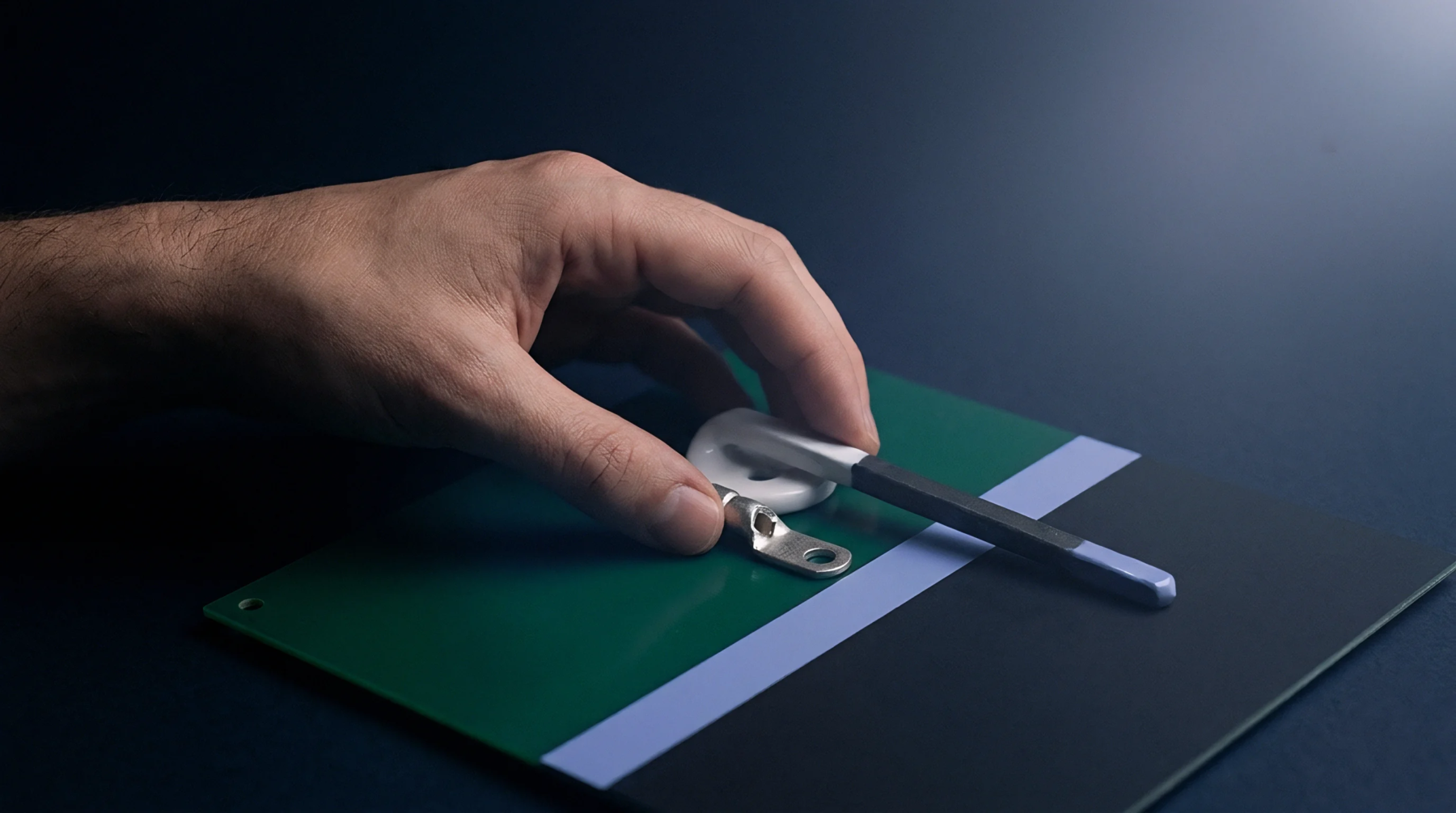
Substrate deflection occurring during the automated electrical verification of a circuit board. Minimizing in circuit test flexure prevents the cracking of brittle solder joints and the delamination of internal copper traces. It is a critical parameter in high-volume electronics manufacturing environments.
Fixture Design
Rigid support pillars placed strategically beneath the board counteract the pressure exerted by the spring-loaded pogo pins. If these supports are misaligned, the resulting in circuit test flexure creates localized stress concentrations that exceed the tensile strength of the laminate. Strain gauge testing during fixture commissioning identifies these hazardous zones.
Strain Limit
Acceptable thresholds for this deformation are usually defined by the most sensitive component on the assembly. Most industrial standards cap in circuit test flexure at levels that prevent the catastrophic failure of fine-pitch ball grid arrays. Exceeding these limits during a single test cycle can induce latent defects that only appear after the product is shipped to the end user.
Accuracy of the measurement depends on the placement of sensors relative to the points of maximum probe density.
Measurement Process
High-speed data loggers record the strain profile during the full travel of the press plate. The peak in circuit test flexure occurs at the moment of maximum probe engagement. Analysis of the resulting waveform confirms that the mechanical damping and support layout are sufficient for the production volume.