Printed Circuit Board Warpage Effects on Sensor Offsets
Board warpage transfers mechanical stress through solder joints to sensor dies, driving offset errors that demand symmetrical layout and firmware bias trimming.


Slab

Thermomechanical Strain Transfer to Encapsulated Dies
Mechanical deformation of a printed circuit board translates directly into stress components applied to surface-mounted silicon dies. When an FR-4 laminate undergoes out-of-plane bowing or twisting during assembly reflow or operational thermal cycling, the substrate flexure creates a bending moment across component land patterns. Surface-mount solder joints act as rigid mechanical links that transmit substrate shear strain into the package interposer, leadframe, and mold compound.
Silicon micro-electro-mechanical systems (MEMS) and precision analog sensing elements possess inherent piezoresistive and piezoelectric sensitivities. Applied mechanical stress alters the crystalline lattice spacing of internal piezoresistors or changes the mechanical gap of capacitive sensing structures, altering the baseline electrical output under zero-input conditions.
Substrate bow and twist limits established by IPC-6012 Class 3 permit up to 0.50 percent maximum finished board warpage for surface-mount components, while Class 2 permits 0.75 percent. Mechanical stress alters register outputs. A 0.50 percent board curvature over a 100-millimeter span induces tensile strain on the top copper surface reaching 300 to 500 microstrain depending on board thickness and layer construction.
When a 3 mm by 3 mm Land Grid Array (LGA) MEMS accelerometer sits within this strain field, the solder joints experience asymmetrical shear forces ranging from 12 to 28 megapascals (MPa). The resulting stress field propagates through the package substrate and epoxy mold compound, arriving at the suspended silicon proof mass anchor points as an anisotropic stress tensor.
Normal stress components along the orthogonal axes of the die modify piezoresistive coefficients according to the silicon piezoresistance matrix. For single-crystal silicon oriented along the (100) plane, longitudinal piezoresistive coefficients (π11 and π12) convert longitudinal stress (σxx) and transverse stress (σyy) into fractional resistivity changes (Δ ρ / ρ0). In a 3-axis piezoresistive accelerometer or pressure sensor, an asymmetrical normal stress difference (σxx – σyy) of 10 MPa shifts the zero-g offset voltage by 15 to 45 millivolts, corresponding to a zero-g bias error of 30 to 90 mg (where 1 g = 9.81 m/s²).
Corner pads absorb peak shear.
A four-layer FR-4 assembly with 0.5 percent bow transmits up to 45 megapascals of mechanical stress to a wafer-level chip-scale package.

Diffusional Strain and Permanent Reflow Displacement
Thermal excursions during convection solder reflow impose transient and permanent warpage on multi-layer board assemblies. Differences in the coefficient of thermal expansion (CTE) between woven glass-epoxy FR-4 laminate (≈ 14-17 p±/circC in-plane), copper traces (≈ 16.5 p±/circC), and silicon dies (≈ 2.6 p±/circC) create thermal strain during the peak reflow phase (245circC to 260circC). As the assembly cools past the liquidus temperature of SAC307 or SAC305 solder (217circC), the solder locks the package to the substrate while the PCB substrate remains thermally expanded.
Solder thickness alters coupling efficiency.
Subsequent cooling to room temperature (25circC) forces the PCB substrate to contract faster than the encapsulated silicon. The solder joints freeze in a state of permanent residual shear stress. Plastic deformation within the FR-4 resin matrix prevents the board from returning to its original planar state, leaving a permanent static warpage.
Static offset shifts observed after board assembly stem primarily from this frozen reflow stress profile rather than raw silicon manufacturing variation.
- Out-of-plane flexure induces differential normal stress across the sensor die anchor points, driving direct zero-bias electrical drift.
- In-plane asymmetrical strain distorts differential capacitive comb fingers, generating false acceleration or rotation signals inside host registers.
- Thermal expansion mismatch forces solder joints into plastic shear, creating temperature-dependent offset hysteresis during environmental ramping.
- Localized board twisting applies torsional moment to package corners, shifting multi-axis cross-axis sensitivity matrix values by up to 1.8 percent.
Ignoring board curvature during layout planning guarantees high scrap rates at final testing and unacceptable field offset drift across operational temperature cycles.
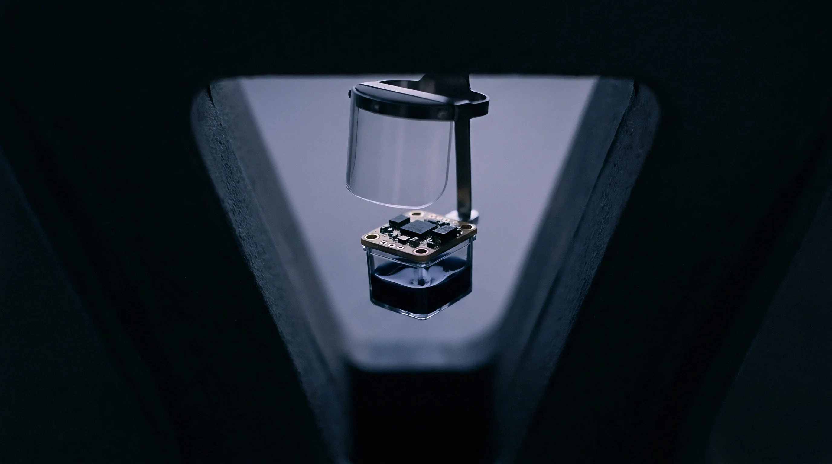

Mold
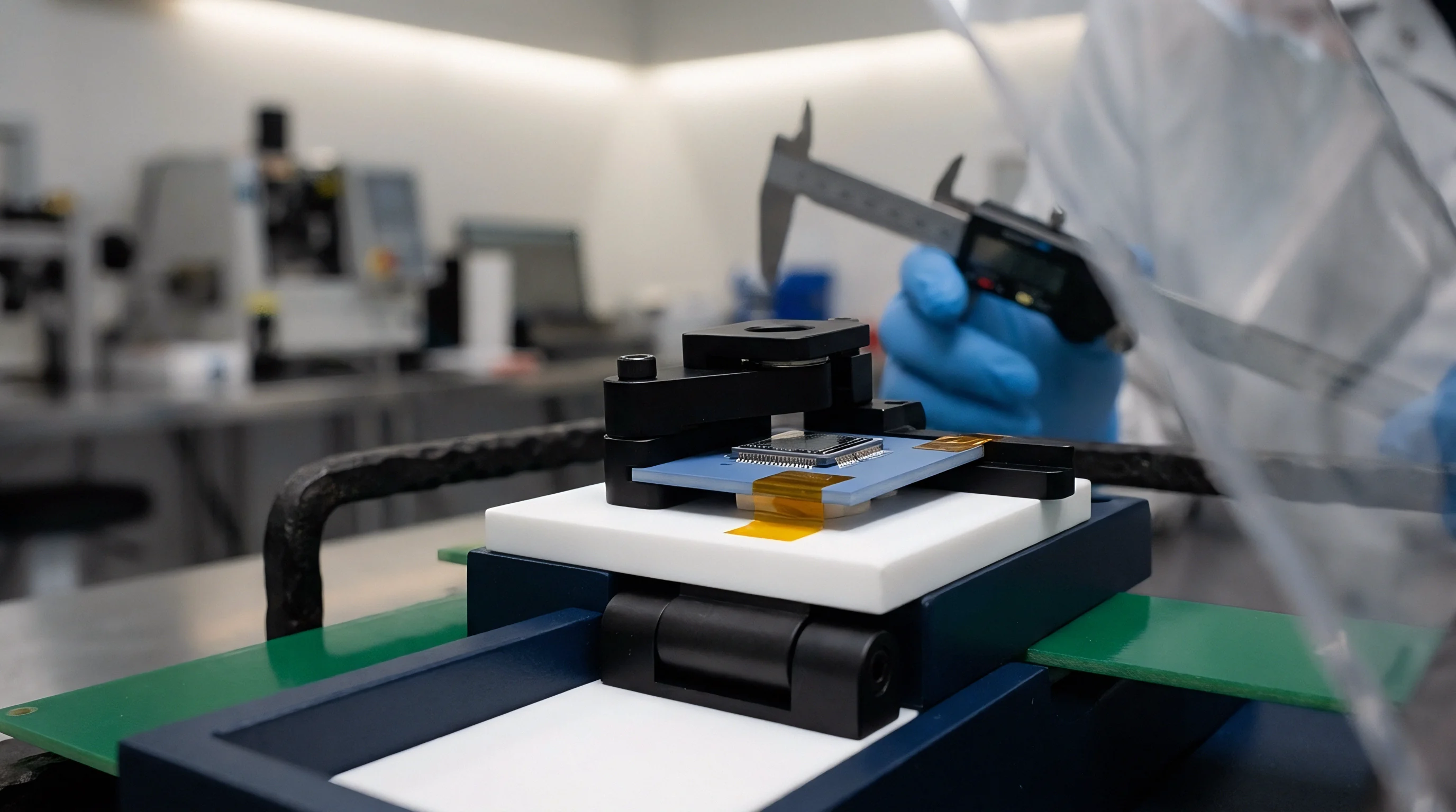
Package Structural Sensitivity and Stress Mitigation
Package geometry determines how efficiently printed circuit board strain reaches the encapsulated sensing element. Silicon die integration options span Wafer-Level Chip-Scale Packages (WLCSP), Land Grid Array (LGA), Quad Flat No-Lead (QFN), open-cavity SMT housings, and standalone cabled assemblies. Wafer-level packages lack stress buffering.
In a WLCSP format, solder bumps connect the silicon die directly to copper land patterns on the board. Without an organic interposer substrate or molding compound to damp mechanical energy, WLCSP devices experience unmitigated strain transfer; a 0.2 percent substrate bending strain can produce zero-g offset shifts exceeding 120 mg in triaxial inertial sensors.
Plastic LGA and QFN packages insert a multi-layer BT-epoxy or copper leadframe substrate combined with a transfer-molded epoxy molding compound (EMC). The mold compound acts as a mechanical mechanical buffer, absorbing a fraction of the substrate flexure before it reaches the die mount pad. The mechanical stiffness (Young’s modulus) of the mold compound determines stress transmission.
Low-stress epoxy mold compounds with a Young’s modulus below 15 gigapascals (GPa) at room temperature reduce offset sensitivity to board flexure by 35 to 50 percent compared to standard rigid compounds (22 to 28 GPa).
| Package Variant | Substrate Attachment | Mechanical Stress Buffer | Zero-g Offset Sensitivity | Landed Cost Range (USD) |
|---|---|---|---|---|
| WLCSP (0.4 mm pitch) | Direct SAC305 Bumps | None (Bare Die) | 80 to 150 mg / 0.5% flex | $0.18 to $0.35 |
| Plastic LGA (16-pin, 3×3 mm) | BT-Epoxy Substrate | Low-Modulus Mold Compound | 15 to 35 mg / 0.5% flex | $0.42 to $0.85 |
| Exposed-Pad QFN (24-pin) | Copper Leadframe + Die Attach | Standard Epoxy Molding | 30 to 70 mg / 0.5% flex | $0.38 to $0.70 |
| Open-Cavity LGA (Pressure) | Substrate + Silicone Gel | Silicone Gel Encapsulation | 0.8 to 2.5 hPa / 0.5% flex | $0.95 to $1.80 |
| Cabled Module / Probe | Isolated Internal PCB | Potted Thermoplastic Shell | < 2 mg / 0.5% flex | $4.50 to $12.00 |
Exposed central thermal pads on QFN packages introduce severe mechanical coupling. Soldering the large center pad to an inner-layer ground plane locks the package center firmly to the PCB laminate. Board bowing flexes the leadframe directly, imposing high tensile or compressive strain on the center of the silicon die.
Omitting solder paste from the central pad aperture or using a segmented windowpane stencil pattern reduces center-pad solder coverage to 30-40 percent, lowering thermal-pad stress coupling by over 60 percent.
IPC-6012 Class 3 specifications cap total printed board bow and twist at 0.50 percent to prevent zero-g offset drift beyond device trim range.
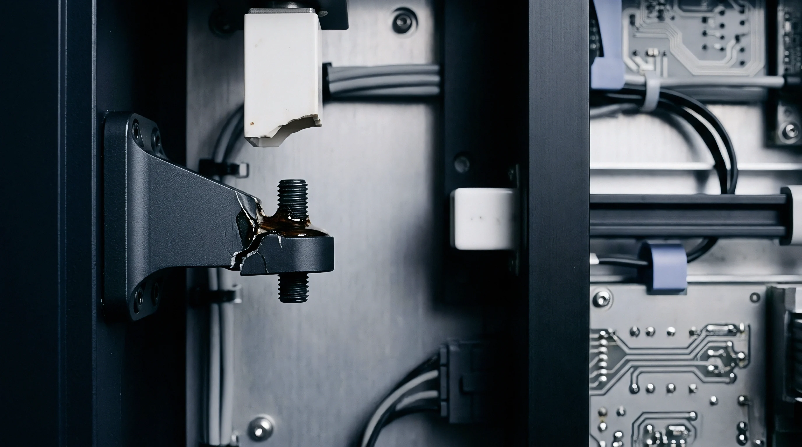
Land Pattern Layout Optimization
Board footprint construction controls the localized symmetry of solder joint stress vectors. Copper trace geometry, solder mask openings, and inner-layer copper distribution govern mechanical torque applied to component leads. Copper symmetry reduces local bowing.
- Convert land patterns to Non-Solder-Mask Defined (NSMD) pads to ensure uniform 360-degree solder wetting around outer pad perimeters, preventing asymmetrical stress concentration along solder mask edges.
- Enforce symmetrical copper trace entries by ensuring signal traces route out of opposing pads with identical widths (e.g. 0.12 mm trace width for 0.25 mm pads) to balance thermal dissipation and surface tension during solder cooling.
- Add copper thieving patterns on adjacent inner layers beneath the sensor package footprint, maintaining a uniform 50 percent copper density across a 10 mm radial boundary to prevent localized laminate warping.
- Omit non-critical corner pads or floating solder land anchors when package drawings permit, reducing mechanical strain transfer from the highest-displacement corners of the package footprint.
Component vendors frequently argue that zero-bias output shifts fall under customer assembly handling responsibilities rather than device manufacturing defect liabilities.


Register

Host Firmware Offset Compensation Mechanics
Host firmware frequently assumes zero-bias conditions established in free space survive surface-mount assembly. Solder reflow warpage invalidates factory One-Time Programmable (OTP) trim settings by introducing post-assembly mechanical stress. When an assembled board boots, the sensor digital bus (I2C or SPI) reports baseline readings offset from nominal values.
Digital accelerometers, gyroscopes, and magnetometers expose internal offset trim registers designed to absorb post-assembly bias errors. Host code must quantify static warpage shifts before writing correction coefficients to internal volatile memory or system EEPROM.
Factory trim registers have limits. Register write sequences over I2C or SPI target device-specific register blocks. A 3-axis digital accelerometer typically provides 8-bit or 16-bit offset compensation registers for X, Y, and Z axes (e.g.
OFFX_USER , OFFY_USER , OFFZ_USER ). Each LSB in a 16-bit offset register corresponds to a fixed sensitivity fraction, such as 0.98 mg/LSB over a ±2g full-scale range. Host firmware reads baseline offsets.
Executing an auto-zero routine requires the host microcontroller to poll the sensor bus while the device remains static and flat. The firmware averages 256 or 512 raw data samples over a low-pass filter window to eliminate environmental vibration noise. The computed mean vector (barX, barY, barZ) is compared against the theoretical gravity vector (0, 0, +1g).
The calculated difference vectors Δ X = 0 – barX, Δ Y = 0 – barY, and Δ Z = 1g – barZ are converted to twos-complement binary words and written back to the user offset registers via SPI transactions running up to 10 MHz or I2C fast mode at 400 kHz.
Symmetrical copper distribution across all inner layers prevents localized board twisting during solder reflow cooling.

Dynamic Warpage against Static Reflow Offset
Static zero-g offset calibration performed at 25circC room temperature fails when the operating environment sweeps across broad thermal spans (-40circC to +105circC). Dynamic warpage arises because the coefficient of thermal expansion mismatch between FR-4 and silicon produces variable bending moments as temperature changes. The PCB bow changes shape dynamically, creating temperature coefficient of offset (TCO) drift that mimics motion or pressure changes.

How Does Host Code Distinguish Board Warpage from Die Drift?
Disentangling substrate-induced strain drift from pure silicon sensor thermal drift demands multi-point thermal calibration or continuous online algorithmic filtering. Silicon-level drift follows predictable polynomial curves supplied in datasheets (e.g. ± 0.2 mg/circC).
Substrate flexure drift exhibits non-linear, hysteretic trajectories caused by mechanical relaxation in the solder joints and PCB laminate. Thermal expansion drives dynamic drift.
- System-level static zeroing executes during initial power-up at factory test, writing static reflow offset deltas directly to non-volatile memory.
- Temperature-indexed lookup tables stored in host Flash memory apply secondary offset corrections based on real-time internal sensor temperature register readings.
- High-pass software filtering suppresses slow thermal-warpage baseline drift in dynamic applications like motion tracking or vibration analysis.
- Extended Kalman filtering blends inertial sensor outputs with secondary references (such as optical flow or GPS) to dynamically estimate and track time-varying offset bias vectors.
Recalibrating baseline zero offsets after final mechanical assembly removes both board warpage residual strain and enclosure clamping forces in a single software operation.

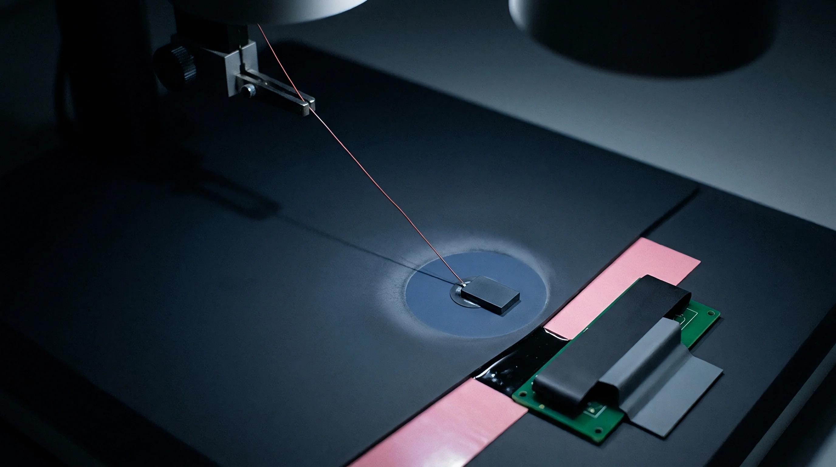
Scan
Optical Warpage Profiling Techniques
Optical profiling under thermal ramp conditions isolates localized board flexure from total panel deformation. Measuring out-of-plane displacement (w) of a printed circuit board across reflow temperatures requires non-contact optical metrology. Shadow Moiré topography and Digital Image Correlation (DIC) serve as the primary test standards defined under IPC-TM-650 Method 2.4.22.
Shadow Moiré projects a grating line pattern onto the PCB substrate surface through a glass reference grating. Shadow fringe lines generated by geometric interference correspond to contours of equal out-of-plane elevation.
Modern automated shadow moiré systems heat test vehicles inside an infrared convection chamber while high-resolution CMOS cameras capture fringe movement from 25circC up to 260circC reflow peak profiles. Height resolution down to 1.0 micrometer (μm) enables precise mapping of the displacement field across the land pattern area. Thermal profile graphs identify the exact temperature phase where laminate glass transition (Tg) changes FR-4 flexural modulus from approximately 24 GPa down to 2 GPa, causing rapid out-of-plane displacement spikes.
| PCB Substrate Material | Glass Transition (Tg) | Max Reflow Warpage (260°C) | IPC Class 3 Pass Limit | Measured Offset Shift (LGA-16) |
|---|---|---|---|---|
| Standard FR-4 (Mid-Tg) | 150°C | 0.82% Bow / Twist | Fail (>0.50%) | 42 to 68 mg |
| High-Tg FR-4 (Isola IS410) | 180°C | 0.38% Bow / Twist | Pass (<0.50%) | 12 to 22 mg |
| Polyimide / Glass (Flex-Rigid) | 250°C | 0.22% Bow / Twist | Pass (<0.50%) | 6 to 11 mg |
| Halogen-Free High-Tg FR-4 | 170°C | 0.45% Bow / Twist | Pass (<0.50%) | 18 to 31 mg |
Gel encapsulation cushions external force. Thicker boards resist bending moments. Elevating board thickness from 1.0 mm to 1.6 mm increases flexural rigidity by a factor of four, dramatically reducing dynamic shadow moiré fringe density during peak reflow ramps.
Factory offset calibration performed prior to mechanical housing integration fails to capture enclosure mounting stress.
Verifying Solder Joint Stress Distribution
Integrating strain gauge rosettes on test printed circuit boards validates finite element analysis (FEA) models of sensor land patterns. Miniature triaxial strain rosettes bonded directly adjacent to package corner pads measure real-time microstrain during assembly, reflow cooling, and enclosure screw torquing. Mounting hardware introduces mechanical strain.
Torquing a PCB fastening screw with 0.4 Newton-meters (N·m) of torque into an un-shimmed boss can induce localized microstrain exceeding 800 μvarε, shifting sensor zero offsets by amounts far larger than those generated by raw reflow warpage.
Adopting IPC-TM-650 Method 2.4.22 section 5.2 forces board fabricators to provide optical strain data across reflow temperatures, eliminating unverified substrate warpage claims during lot acceptance.

Margin

Make-or-Buy Architecture Arithmetic
Financial trade-offs between component package selection and calibration factory throughput shape total bill of materials costs. Selecting a raw bare-die WLCSP accelerometer at $0.22 unit price looks attractive on an initial bill of materials (BOM). Unbuffered WLCSP components suffer high yield loss during factory zero-g offset screening due to PCB warpage sensitivity.
If board flexure drives 8 percent of assembled boards beyond the maximum register offset trim limit (e.g. > ±100 mg), the scrap and rework cost rapidly consumes the initial component savings.
Yield drops when warpage spikes. Solder reflow creates permanent displacement. Unbalanced copper pulls the board.
Evaluating an alternative packaging route highlights the financial impact of stress isolation strategies across production volumes.
| Integration Option | Unit BOM Price | PCB Layout / Stiffener Cost | Factory Calibration Time | Warpage Yield Scrap Rate | Total Effective Cost (100k Units) |
|---|---|---|---|---|---|
| Bare WLCSP (Direct Mount) | $0.25 | $0.00 | 6.5 seconds ($0.13) | 7.5% | $0.41 per unit |
| Standard LGA (3×3 mm) | $0.55 | $0.02 (Thieving/NSMD) | 2.0 seconds ($0.04) | 1.2% | $0.62 per unit |
| LGA + Aluminum Stiffener | $0.55 | $0.35 (Mechanical Plate) | 1.5 seconds ($0.03) | 0.2% | $0.93 per unit |
| Standalone Cabled Module | $4.80 | $0.00 (Isolated Mount) | 0.0 seconds ($0.00) | 0.0% | $4.80 per unit |
A worked financial scenario demonstrates the arithmetic governing package choice. Assume a production run of 100,000 units. Opting for a standard $0.55 LGA package with an optimized NSMD footprint and 50 percent copper thieving incurs $0.02 in board fabrication optimization and $0.04 in automated factory offset calibration testing (running a 2.0-second auto-zero program over I2C).
At a 1.2 percent warpage scrap rate, the effective landed cost settles at $0.62 per unit.
Attempting to solve warpage errors by adding a mechanical aluminum stiffener bracket beneath the sensor site adds $0.35 in hardware and placement labor. The stiffener suppresses scrap rates to 0.2 percent, but total effective unit cost jumps to $0.93. The pure software calibration pathway using host offset register writes remains the most commercially viable strategy, provided the package choice keeps raw physical offset shifts within the digital register compensation range.

Sourcing Dossier and Document Requirements
Purchasing specifications for precision MEMS and analog sensor assemblies must explicitly bind suppliers to defined mechanical strain and warpage tolerances. Standard component datasheets quote performance figures under zero-stress sockets, ignoring real-world SMT assembly realities. Procurement teams must require specific technical commitments within supplier quality contracts.
- Maximum allowable reflow warpage limits specified under IPC-6012 Class 3 (0.50%) with compulsory IPC-TM-650 Method 2.4.22 test reports attached to every laminate lot shipment.
- Guaranteed user offset register ranges ensuring digital trim registers provide sufficient LSB span (minimum ±150 mg or ±20 hPa equivalent) to absorb worst-case SMT residual stress.
- Encapsulation material modulus guarantees defining Young’s modulus caps (<15 GPa) for transfer-molded epoxy resins across operational temperature bands.
- Symmetrical land pattern guidelines mandated within component application notes, specifying exact NSMD aperture dimensions and inner-layer copper thieving keep-out rules.
Whether automated test equipment can dynamically separate permanent solder reflow strain from elastic enclosure flexure during five-second production screening remains unresolved across high-volume assembly lines.