Implementing Strain Rate Dependency Matrices in Explicit Drop Shock Simulations
Strain rate matrices in explicit drop simulation prevent premature solder ball fatigue failure prediction by scaling material yield stress with impact velocity.


Shock
Board-level drop shock testing exposes surface-mount IC packages to transient accelerations up to fifteen hundred g within five hundred microseconds. Standard mechanical testing relies on static or quasi-static stress-strain curves, which break down in explicit drop shock simulations because electronic materials yield in a strongly rate-dependent manner. At strain rates above one thousand reciprocal seconds, lead-free solders, copper traces, and organic substrates undergo significant dynamic strain hardening.
When explicit finite element solvers calculate structural responses using purely static material definitions, the computed plastic strain overestimates physical deformation. This overestimation predicts premature solder joint detachment while underestimating the peak shock energy transmitted directly to the embedded silicon die.
Accurate explicitly integrated simulations require strain rate dependency matrices across all structural constituents. Explicit codes like LS-DYNA, Abaqus Explicit, and ANSYS AUTODYN evaluate element stress states at microsecond timesteps. If the solver evaluates a solder sphere or package lead without a strain rate matrix, effective yield stress stays fixed regardless of impact velocity.
In physical drop events governed by JEDEC JESD22-B111 specifications, actual strain rates in corner solder balls routinely span four orders of magnitude during primary shock wave propagation.
| Material System | Quasi-Static Yield Stress (MPa) at 0.001 s⁻¹ | High Strain Rate Yield Stress (MPa) at 1000 s⁻¹ | Dynamic Amplification Factor | Primary Deformation Mode |
|---|---|---|---|---|
| SAC305 (96.5Sn-3.0Ag-0.5Cu) | 32.5 | 88.0 | 2.71 | Twinning & Dislocation Glide |
| SAC105 (98.5Sn-1.0Ag-0.5Cu) | 24.0 | 71.5 | 2.98 | Bulk Plastic Shear |
| E-Glass Epoxy Substrate (Out-of-Plane) | 180.0 | 245.0 | 1.36 | Interlaminar Delamination |
| Rolled-Annealed Copper Foil | 195.0 | 310.0 | 1.59 | High-Density Dislocation Stacking |
| Silicone Underfill Compound | 45.0 | 112.0 | 2.49 | Viscoelastic Glass Transition Shift |
Tabular parameters come from dynamic compression tests, while split-Hopkinson pressure bars provide rate constants. Integrating these inputs ensures transient stress wave reflections across package interfaces match accelerometer readings. Ignoring the dynamic amplification factor leads finite element models to predict premature intermetallic micro-cracking where physical parts survive, forcing hardware teams into unnecessary redesigns.
Substrate copper foils exhibit a forty percent yield strength elevation when loading rates transition from quasi-static tests to explicit drop impact velocity.
Determining whether non-linear viscoelastic relaxation effects during the five-hundred-microsecond pulse alter ultimate solder crack propagation pathways remains an active area of empirical research.


Matrices
Explicit dynamic solvers evaluate plastic deformation by checking instantaneous strain rates against pre-tabulated material curves. Modern material cards rely on empirical models like Cowper-Symonds or full multi-dimensional lookup matrices. The Cowper-Symonds formulation scales effective yield stress using two material constants, C and P, raising the ratio of plastic strain rate to the reference parameter C to the exponent inverse P.

Constitutive Rate Equations for Solder Alloys
Extracting parameters for low-melting-point solders presents distinct challenges. Lead-free alloys operate at high homologous temperatures even at room ambient, so yield stress depends simultaneously on strain rate, total equivalent plastic strain, and localized heat buildup. Simple Cowper-Symonds scaling tends to over-predict yield stress at ultra-high strain rates when dislocation drag takes over from thermal activation.
To avoid this, strain-rate-dependent multi-curve plastic models (such as LS-DYNA MAT_024) define yield stress against plastic strain across discrete curves spanning from 0.0001 to 10000 reciprocal seconds.
JEDEC JESD22-B111 test conditions specify a half-sine shock pulse of 1500 g intensity and 0.5 millisecond duration, driving localized solder joint strain rates beyond three thousand reciprocal seconds.

Matrix Formulation Risks in Explicit Solvers
Misconfigured strain rate matrices degrade solver convergence and generate unphysical stress peaks under transient loading. The primary modeling risks stem from mathematical extrapolation, sparse data sampling, and uncalibrated damping factors:
- Extrapolation saturation failure occurs when element strain rates exceed the highest tabular entry, causing the solver to default to flat yield values or unbounded linear extrapolation.
- High-frequency slope noise arises from discrete curve-fitting errors, creating fictitious stress waves that travel through substrate traces into solder balls.
- Asymmetric tension-compression scaling occurs when isotropic rate-scaling factors are applied indiscriminately to anisotropic substrate composites and thin-film metallizations.
- Artificial strain softening appears when localized thermal dissipation from rapid plastic work is not coupled to yield stress matrix updates.
Solder spheres experience asymmetric shear loading. Integrating separate tension-, compression-, and shear-rate curves prevents premature element deletion in the outer ball grid array connections. Solvers interpolate between discrete strain rate columns using logarithmic mapping to capture the steep yield stress escalation between ten and one thousand reciprocal seconds.
Building material tables with smooth, continuous rate derivatives prevents artificial energy dissipation across high-strain interfaces.


Mesh
Spatial discretization determines how dynamic stress waves propagate from PCB traces into package interconnects. An explicit drop shock simulation needs sub-millimeter refinement around solder ball necks, intermetallic compound layers, and copper pads. The solver’s stable timestep scales directly with the smallest element length in the mesh, governed by the Courant-Friedrichs-Lewy condition where timestep equals element length divided by acoustic wave speed.

Explicit Stability Limits and Element Density
Refining element size in a wafer-level chip-scale package solder joint from fifty micrometers down to five increases stress resolution near critical interfaces. Because Courant conditions dictate the timestep, cutting element edge length by a factor of ten drops the explicit timestep from twenty nanoseconds to two nanoseconds, increasing runtime by orders of magnitude. Mesh design must balance spatial resolution against computational feasibility.
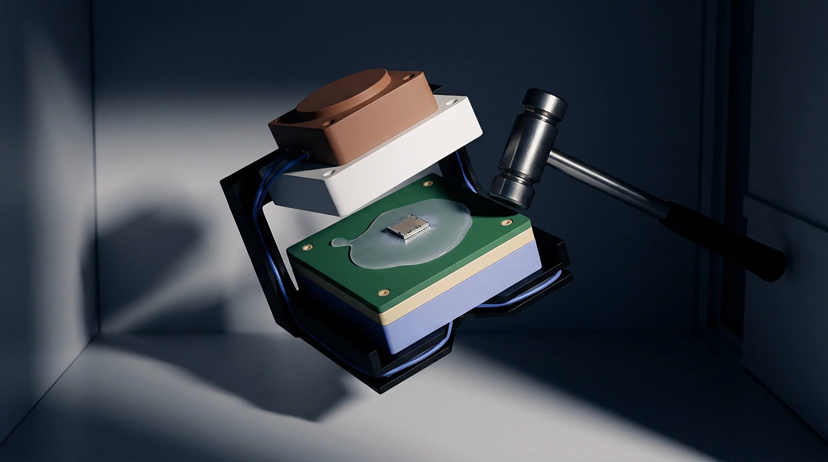
Do Higher Strain Rate Interpolation Steps Suppress Solver Oscillations?
Denser strain rate interpolation steps inside material definitions smooth stress gradients across small elements under transient shock loads. When a shock wave hits an un-underfilled chip-scale package, element strain rates spike within fractions of a microsecond. Coarse matrices cause step-function jumps in element stiffness that trigger high-frequency numerical ringing.
Finer interpolation steps allow the solver to scale stress states smoothly, suppressing numerical oscillations without resorting to excessive bulk viscosity.
| Solder Neck Mesh Size (µm) | Explicit Timestep (ns) | Calculated Peak Strain Rate (s⁻¹) | Peak Effective Stress (MPa) | Compute Time per 2 ms Event (CPU Hours) |
|---|---|---|---|---|
| 100.0 | 38.2 | 450 | 62.4 | 1.2 |
| 50.0 | 18.5 | 1250 | 78.1 | 4.8 |
| 25.0 | 8.9 | 2800 | 94.5 | 22.5 |
| 10.0 | 3.4 | 3950 | 108.2 | 145.0 |
| 5.0 | 1.1 | 4200 | 112.0 | 780.0 |

Worked Matrix Calibration Sequence
Translating raw dynamic test data into stable explicit solver matrices requires a systematic transformation sequence:
- Raw high-rate strain data acquisition isolates true plastic strain by subtracting elastic compliance curves collected on split-Hopkinson pressure bars and high-speed servo-hydraulic frames.
- Data smoothing and filtering removes mechanical resonance noise from load cell signals using a digital lowpass Butterworth filter with a fifty-kilohertz cutoff.
- Interpolation matrix construction tabulates yield stress across log-spaced strain rate intervals from quasi-static to ten thousand reciprocal seconds.
- Single-element validation runs confirm that single-element dynamic shear simulations match input material curves without numerical drift or energy anomalies.
- Global package drop execution applies the calibrated matrices to full board models to evaluate transient strain distributions across critical interconnects.
Explicit time integration constrains mesh density. Choosing an optimal element size requires checking that localized strain rate gradients remain stable across adjacent element rows. If neighboring elements differ in strain rate by more than two orders of magnitude at peak acceleration, the mesh is too coarse to capture stress wave attenuation.
SAC305 interconnect failure predictions under explicit shock load shift by twenty-eight percent when solver rate matrices are interpolated logarithmically rather than linearly.
Coarse meshing along high-gradient solder ball boundaries clips peak dynamic stresses, resulting in unexpected package detachment during qualification testing.
Die
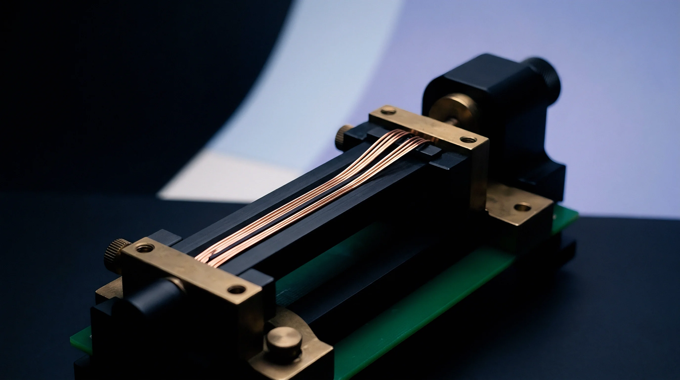
Substrate flexure imparts high-velocity shear loads directly through solder spheres into the package base, driving internal silicon strain. In MEMS sensors, inertial measurement units, and precision analog front-ends, dynamic package strain shifts calibration offsets, induces signal drift, and corrupts post-drop register integrity.
Board flexure alters zero-g sensor offsets because piezoresistive structures inside silicon dies change electrical resistance under changing mechanical stress. When the package substrate flexes, stress travels through die-attach adhesives into sensitive Wheatstone bridge elements. Explicit simulations using rate-dependent matrices capture these dynamics, predicting temporary signal saturation, long-term calibration offsets, or wire-bond lifting.
Board flexure during primary shock impact transfers shear stress directly into the die cavity, inducing sensor zero point drift before physical micro-cracking initiates.
Evaluating post-drop signal stability and structural integrity follows a standard bench test sequence:
- Record baseline zero-g offsets and full-scale sensitivity calibration data over the digital bus (SPI or I2C) before drop testing.
- Mount the printed circuit assembly on a drop shock tower configured for JEDEC JESD22-B111 pulses.
- Apply single-axis half-sine acceleration shock pulses while continuously logging bus data under power.
- Read post-impact calibration registers to quantify static output drift caused by residual stress.
- Cross-section selected packages to correlate predicted element strain concentrations with silicon micro-cracking or underfill delamination.
Underfill resins redistribute dynamic shear loads. Formulating high-rate viscoelastic matrices for these materials allows simulations to evaluate how well they isolate silicon dies from high-frequency board flexure. Neglecting strain rate hardening in underfill causes models to over-predict internal die strain while underestimating shear stress on outer solder joints.
Post-drop sensor calibration offsets often stem from internal metallization layer strain rather than substrate warp.
Cost
Choosing between wafer-level chip-scale packaging, quad-flat no-leads, and land grid arrays requires balancing board area against shock survival requirements. Thin WLCSP options save real estate but transfer peak dynamic strain directly into solder connections during impact. QFN packages handle shock better due to compliant lead frames and corner pad geometry, but demand considerably more board area.
Adding capillary or non-conductive underfill cycles increases unit assembly cost while significantly improving drop shock survival. Shock requirements dictate whether a design can use un-underfilled chip-scale packages or must absorb the capital and cycle-time overhead of underfill dispensing and curing lines.
| Package Variant | PCB Area Footprint (mm²) | Maximum Shock Resistance without Underfill (g) | Underfill Requirement Threshold | Relative Landed Component Cost (100k Volume) |
|---|---|---|---|---|
| WLCSP (0.4mm pitch) | 3.2 | 800 | Mandatory above 800 g | 1.00 |
| BGA (0.8mm pitch) | 16.0 | 1200 | Recommended above 1200 g | 1.35 |
| LGA (0.5mm pitch) | 12.25 | 1500 | Optional (Depends on PCB thickness) | 1.42 |
| QFN (0.5mm pitch) | 25.0 | 3000 | Not Required | 1.18 |
| Molded Module (Co-Design) | 36.0 | 5000+ | Integrated Over-Mold | 2.10 |
While physical drop testing validates material parameters, relying on accurate explicit FEA models allows engineering teams to finalize package selection early in development. Realistic simulations prevent late-stage qualification failures, avoiding board spins, stencil redesigns, and production delays.
Invoking IPC J-STD-001 Class 3 shock compliance clauses shifts financial liability for un-underfilled WLCSP shear failures back to the assembly facility.