Thermal Zero Hysteresis Mitigation through Micro Dosing Fluid Controls
Thermal zero hysteresis in micro dosing controls is mitigated by active dual vector temperature compensation and low expansion wetted materials.


Origin
Micro-dosing fluid delivery systems operating below one microliter register measurable baseline zero shifts during thermal fluctuations. Physical expansion of internal fluid channels, shifts in fluid density, and varying strain across piezoelectric or electromagnetic actuators together introduce offset errors. As ambient temperature cycles between operating limits, the zero output follows different paths during heating and cooling.
This non-reversible progression forms a hysteresis loop that undermines volumetric repeatability in automated dispensing.
Precision micro-dispense valves and low-flow thermal mass flow meters rely on micrometer-scale mechanical tolerances. Tiny temperature shifts distort the internal fluid cavity volume, altering hydraulic resistance across the orifice. At the same time, thermal gradients across actuator mounts generate mechanical stresses that do not relax as quickly as heat dissipates.
Consequently, a dosing valve returning to its de-energized position after a thermal excursion comes to rest at an altered physical location, driving systematic volume drift across batch runs.

Mechanisms of Baseline Offset Shift
Thermal zero drift stems from coupled thermo-mechanical and fluidic effects. Metallic and polymeric wetted components expand at different rates governed by their linear thermal expansion coefficients. Invar bodies, stainless steel needles, and fluoropolymer seals expand unevenly, shifting the baseline seat clearance.
Meanwhile, fluid trapped in dead volumes changes density, creating micro-pressures against static pressure transducers under zero-flow conditions.
Piezoceramic actuators driving micro-dosing pins suffer from intrinsic thermal polarization hysteresis. Heating alters ceramic domain alignment, changing stroke length per volt. When cooled, these domain structures retain residual orientation shifts, moving the mechanical zero point.
Strain gauges bonded to flexure elements detect this residual structural stress as apparent fluid pressure, corrupting baseline calibration stability at low flows.
| Material Designation | Coefficient of Thermal Expansion (10⁻⁶/K) | Thermal Conductivity (W/m·K) | Zero Point Recovery Error (% Vol/°C) | Hysteresis Loop Width (°C Cycle) |
|---|---|---|---|---|
| 316L Stainless Steel | 16.0 | 16.3 | 0.085 | 0.42 |
| Titanium Grade 5 (Ti-6Al-4V) | 8.6 | 6.7 | 0.041 | 0.28 |
| Invar 36 (FeNi36) | 1.2 | 10.1 | 0.006 | 0.09 |
| Polyether Ether Ketone (PEEK) | 47.0 | 0.25 | 0.310 | 1.15 |
| Silicon Substrates (MEMS) | 2.6 | 149.0 | 0.011 | 0.04 |

Thermo-Mechanical Relaxation in Micro-Fluid Channels
Mechanical stress accumulates along the wetted path during power cycles or fluid temperature swings. Assembly preloads on elastomer gaskets decay non-linearly across temperature ramps between 15 °C and 50 °C. Under heat, the seal material behaves viscoplastically, flowing slightly under clamp compression and failing to recover its original dimensions when cooled.
Uncompensated Kovar valve bodies demonstrate a zero-flow displacement drift of 0.042 microliters per degree Celsius across a 20 °C to 50 °C thermal ramp.
Micro-fluidic channel geometries deform under localized heating from high-duty actuator cycles. Temperature differences between the manifold body and incoming fluid create localized thermal expansion zones. These local gradients distort the internal pressure distribution, shifting zero-flow differential pressure readings.
The resulting zero wander lingers until thermal equilibrium spreads across the entire manifold structure.
Whether structural thermal relaxation in high-density manifold blocks can be modeled deterministically across multi-axis thermal gradients without continuous inline flow recalibration remains an open empirical question.


Stem
Actuator drive needles and valve stems transmit motion from electronic actuators to fluid orifices. Differential thermal expansion along the stem’s long axis changes both the seating force when closed and the initial displacement point. In high-frequency micro-dosing, friction along stem guides generates localized heat, establishing dynamic thermal gradients between the stem and its outer housing.
As the actuation rod absorbs heat, axial expansion shrinks the gap between the stem tip and valve seat. In normally-closed valves, this expansion preloads the elastomeric seat material, inducing plastic deformation over extended production runs. When shut down, cooling shortens the stem, leaving a wider seating gap that requires higher initial actuator voltage to seal completely, shifting the system baseline.

Actuator Expansion and Seat Compliance
Elastomer and fluoropolymer seats change compliance with temperature. Seat material softens as ambient temperatures rise, allowing the valve pin to penetrate deeper under the same seating force. This deeper seating increases the required stroke length to start fluid flow, showing up as negative zero drift in volume integrators.
Flexure-guided micro-actuators eliminate sliding friction but build up thermal stress in their spring leaves. Heating alters the elastic modulus of beryllium-copper or spring steel flexures, shifting the neutral resting axis. The controller registers this physical shift as an uncommanded displacement offset.
Thermal stabilization time scales directly with the square of the valve body structural mass during rapid environmental transitions.

Structural Creep in Micro-Dispense Assemblies
Long-term thermal cycling causes dimensional drift in sub-millimeter fluid metering assemblies. Repeated heating and cooling drive microscopic slip across mechanical joints, permanently altering internal calibration geometry.
- Stem Axis Thermal Strain mismatch creates mechanical bending moments that tilt the sealing face relative to the seat plane.
- Elastomer Compression Set increases non-linearly above 40 °C, permanently shifting zero-flow needle position.
- Actuator Preload Relaxation reduces seating contact stress, permitting low-pressure fluid weeping at static zero state.
- Thermal Mass Asymmetry between solenoid coils and wetted channels introduces directional baseline hysteresis dependent on duty cycle history.
Thick valve body housings retain heat long after fluid flow stops. As a result, rapid ambient temperature swings destabilize zero settings faster than the housing structure can reach thermal equilibrium.


Offset
Mitigating thermal zero hysteresis requires active compensation built into the control electronics and firmware. While passive material selection reduces the scale of the problem, active offset correction is necessary to eliminate residual drift in high-precision dispensing. Tracking real-time temperature near the valve orifice allows compensation algorithms to adjust actuation timing and stroke profiles on the fly.
Embedded microcontrollers run zero-point offset routines during non-dosing dwell intervals. By sampling zero-flow sensor readings at known temperatures, compensation algorithms calculate the current hysteresis offset along pre-calibrated heating and cooling curves. Dual temperature sensors at the fluid inlet and nozzle tip supply gradient data to refine these zero-trim models.

How Does Active Thermal Trimming Prevent Zero Wander?
Dynamic baseline compensation uses thermal lookup tables paired with real-time temperature differential modeling. To account for structural thermal memory, controllers store separate calibration curves for rising and falling temperature regimes.
- Sample zero-flow baseline outputs during scheduled dwell periods when fluid flow stops.
- Measure temperature simultaneously at the dispense orifice, valve housing, and ambient environment.
- Calculate the rate of temperature change to select the appropriate heating or cooling correction vector.
- Derive the offset correction using polynomial coefficients calibrated across the operating temperature range.
- Apply a voltage bias to the piezoelectric actuator or adjust zero-threshold registers in the flow processor.
- Verify baseline stabilization in pressure or position sensors before starting the next dispensing cycle.

Closed-Loop Micro-Dosing Baseline Correction
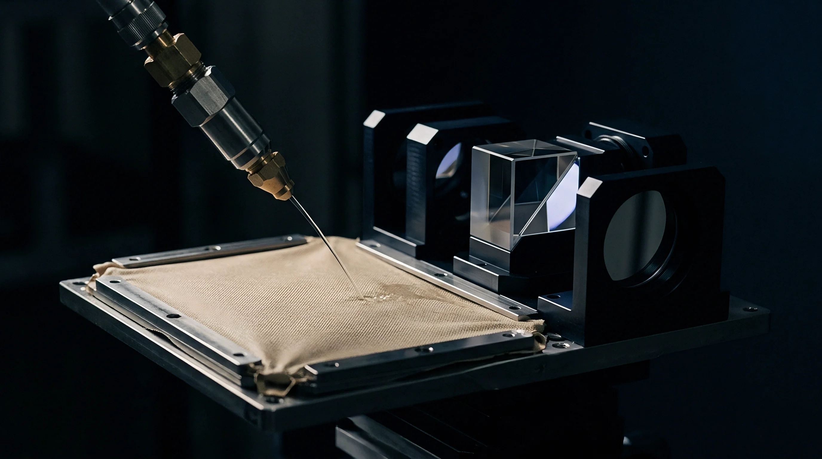
Hardware-level mitigation relies on closed-loop position or pressure feedback at the dispense orifice. Optical linear encoders or capacitive sensors monitor the actual valve stem location, decoupling mechanical expansion from control signals. Direct stem sensing ensures that axial growth triggers immediate controller correction, holding the seat interface at zero position despite temperature swings.
Continuous thermal monitoring at the dispense tip prevents non-linear baseline offsets from degrading micro-dosing stroke repeatability.
Without dual-vector thermal lookup tables, control software falls back on single-point linear coefficients, leaving uncorrected baseline drift during cyclic ambient temperature changes.

Verification
Accredited metrological validation verifies thermal zero hysteresis across specified operating ranges. Testing requires environmental chambers that hold ramp rates within tight tolerances while micro-analytical balances or gravimetric optical systems measure dispensed fluid mass. Protocols specifically isolate ambient thermal effects from actuator self-heating.
ISO/IEC 17025 accredited procedures require continuous zero-flow baseline logging across multi-hour thermal cycles. Standard test cycles ramp ambient temperature from lower to upper specification limits at 1 °C per minute, holding peak temperatures to establish steady state. Continuous logging captures the entire hysteresis envelope, mapping maximum divergence between heating and cooling legs.

Environmental Chamber Testing Methods
Validating zero stability demands tight control over thermal profiles. The valve assembly mounts inside an isolated chamber while fluid feeds from external reservoirs regulated for both pressure and temperature. This setup isolates wetted components from ambient laboratory fluctuations.
Zero-flow signal drift is evaluated using high-speed data acquisition connected to strain gauge, capacitive, or optical sensors. Processing algorithms extract total baseline hysteresis width, defined as the maximum output divergence at any temperature between the heating and cooling curves.
| Uncertainty Contribution Source | Standard Uncertainty Value | Probability Distribution | Sensitivity Coefficient | Uncertainty Contribution (nL/°C) |
|---|---|---|---|---|
| Temperature Sensor Accuracy (Pt100 Class A) | 0.055 °C | Normal (k=1) | 0.42 nL/°C | 0.0231 |
| Chamber Thermal Gradient Drift | 0.120 °C | Rectangular | 0.42 nL/°C | 0.0291 |
| Gravimetric Balance Resolution | 0.001 mg | Rectangular | 1.00 nL/mg | 0.0006 |
| Residual Actuator Hysteresis Memory | 0.082 nL | Normal (k=1) | 1.00 | 0.0820 |
| Fluid Density Thermal Model Uncertainty | 0.015 % | Normal (k=1) | 0.35 nL/% | 0.0053 |
| Combined Expanded Uncertainty (k=2, 95% Confidence Level) | 0.183 nL/°C | |||

Uncertainty Budget Breakdown for Micro-Dosing Zero Baseline
Expanded uncertainty analysis establishes the statistical foundation for baseline datasheet claims. Combined standard uncertainty accounts for sensor calibration tolerances, chamber thermal non-uniformities, barometric variations, and balance precision limits.
- Traceable Temperature References calibrated to national metrology institute standards ensure thermal measurement fidelity during ramp testing.
- Gravimetric Mass Calibration using certified Class E2 weights establishes mass-to-volume translation accuracy for nano-liter fluid volumes.
- Zero-Flow Hydrostatic Isolation eliminates static head pressure variations that could mimic thermal zero drift.
- Data Acquisition Sampling Rate Synchronization prevents phase lag errors between temperature logging and fluid signal channels.
Clause 6.4 of ISO/IEC 17025 mandates traceable calibration evidence for all secondary thermal sensing components that influence primary dispense accuracy.
Datasheets often claim absolute zero stability using figures measured under steady-state conditions, omitting the significant hysteresis errors that occur during dynamic temperature transitions.


Tariff
Sourcing micro-dosing components requires balancing accuracy grade pricing against field failure risks and recalibration maintenance overhead. Higher accuracy grades use low-expansion wetted materials, matched sensors, and factory thermal cycle calibration certificates. Landed unit costs rise non-linearly as specified hysteresis limits tighten.
High-throughput automated applications often absorb higher unit costs to avoid line shutdowns from baseline drift. Unchecked thermal hysteresis leads to volumetric errors that trigger quality rejections, driving up scrap rates in semiconductor, pharmaceutical, and electronics manufacturing.

Grade Classifications and Commercial Sourcing Impact
Micro-dosing control valves fall into distinct precision tiers based on thermal zero stability. Standard industrial valves use basic analog compensation, suitable for controlled environments where ambient shifts stay within ±2 °C. Premium metrology-grade valves feature active dual-vector calibration memory, maintaining a stable baseline across wide thermal swings.
Grade selection directly shapes lifetime operating costs. Lower-tier components reduce initial capital spend but create recurring expenses for manual re-zeroing and field recalibration. Metrology-grade units feature automated internal routines that extend routine maintenance intervals from weeks to a full year.
| Mitigation Architecture Grade | Zero Hysteresis Band (nL/°C) | Initial Unit Cost Premium Multiplier | Annual Recalibration Labor Hours | Estimated 3-Year Landed Ownership Cost |
|---|---|---|---|---|
| Standard Grade (Uncompensated 316L) | 0.850 | 1.0x | 24.0 | Baseline |
| Enhanced Grade (Passive Material Selection – Invar) | 0.120 | 1.8x | 8.0 | -15% Baseline |
| Metrology Grade (Active Thermal Auto-Zeroing) | 0.015 | 3.4x | 1.5 | -38% Baseline |
| Ultra-Precision MEMS (Closed-Loop Optical) | 0.003 | 5.8x | 0.5 | -22% Baseline |

Worked Cost Mechanics of Thermal Baseline Recalibration
Consider an automated dispensing facility operating 50 micro-dosing channels 24 hours a day. Standard valves exhibit an uncompensated thermal zero drift of 0.85 nL/°C, causing batch volume drift during 12 °C ambient temperature swings between day and night shifts.
Assuming a volumetric tolerance of ±1.5%, this drift forces technicians to manually calibrate zero points twice a week for every valve. At a fully burdened labor rate of 85 USD per hour and 0.5 hours per calibration event, manual re-zeroing costs 221,000 USD annually across the 50 channels.
Upgrading to metrology-grade valves with active auto-zeroing adds 1,200 USD per unit in initial procurement, or 60,000 USD in upfront capital. Manual calibration drops to annual verification checks totaling 1.5 hours per unit per year, reducing annual service labor to 6,375 USD. The investment pays for itself within four months on labor savings alone, even before accounting for reduced scrap rates.
Procurement contracts requiring compliance with ISO 10012 clause 7.2 oblige suppliers to supply certified thermal hysteresis test data across the full operating temperature range prior to lot acceptance.