Optimizing Thermal Soak Timing during Sensor Compensation
Dynamic slope verification replaces arbitrary soak timers during sensor compensation, preventing severe polynomial fit distortion and reducing cycle overhead.


Mass
Depending on mechanical volume and encapsulant conductivity, an internal silicon junction can lag behind the exterior of its package by seconds or minutes. If a production line advances a sensor to calibration trim before the sensing die matches the reference fluid temperature, the compensation matrix locks in a transient error. That error then shows up as offset and sensitivity shifts at every target setpoint.
Cycle-time pressure on test lines is real, but cutting dwell times without tracking internal heat flow ruins downstream polynomial coefficients.
Reaching thermal equilibrium means driving heat flux between the calibration bath and the internal die near zero. In a miniature pressure transducer or thermistor assembly, heat must cross several boundaries in sequence: the convective layer in the fluid or air, the steel or ceramic shell, the silicone gel or potting compound, and the die attach adhesive. Each layer adds resistance and capacitance.
Their lumped product forms the device’s thermal time constant. Five time constants let internal temperature settle to 99.3 percent of a step change, whereas three reach only 95 percent ~ leaving a five-percent step error baked into unit memory.
Thick potting compounds isolate internal die structures while extending stabilization intervals past four time constants.
The Biot number governs the internal temperature distribution during any setpoint transition. When internal conduction resistance dwarfs external convective resistance, internal gradients persist long after external surface thermocouples register steady values. External housing readings stabilize rapidly while the inner cavity drifts toward equilibrium at a fraction of that speed.
- Offset voltage drift shifts piezoresistive bridge balance during active thermal gradients, corrupting zero-measurand output.
- Span calculation error distorts full-scale scaling factors when reference readings are taken during lingering transients.
- Package stress relaxation creates secondary shifts as potting compounds and epoxy adhesives redistribute strain over long stabilization windows.
- Premature coefficient burn writes incorrect polynomial parameters into non-volatile memory before the sensing element settles.
Line managers often take component makers at their word that twenty seconds in a stirred chamber guarantees full thermal stabilization across every surface-mount geometry.
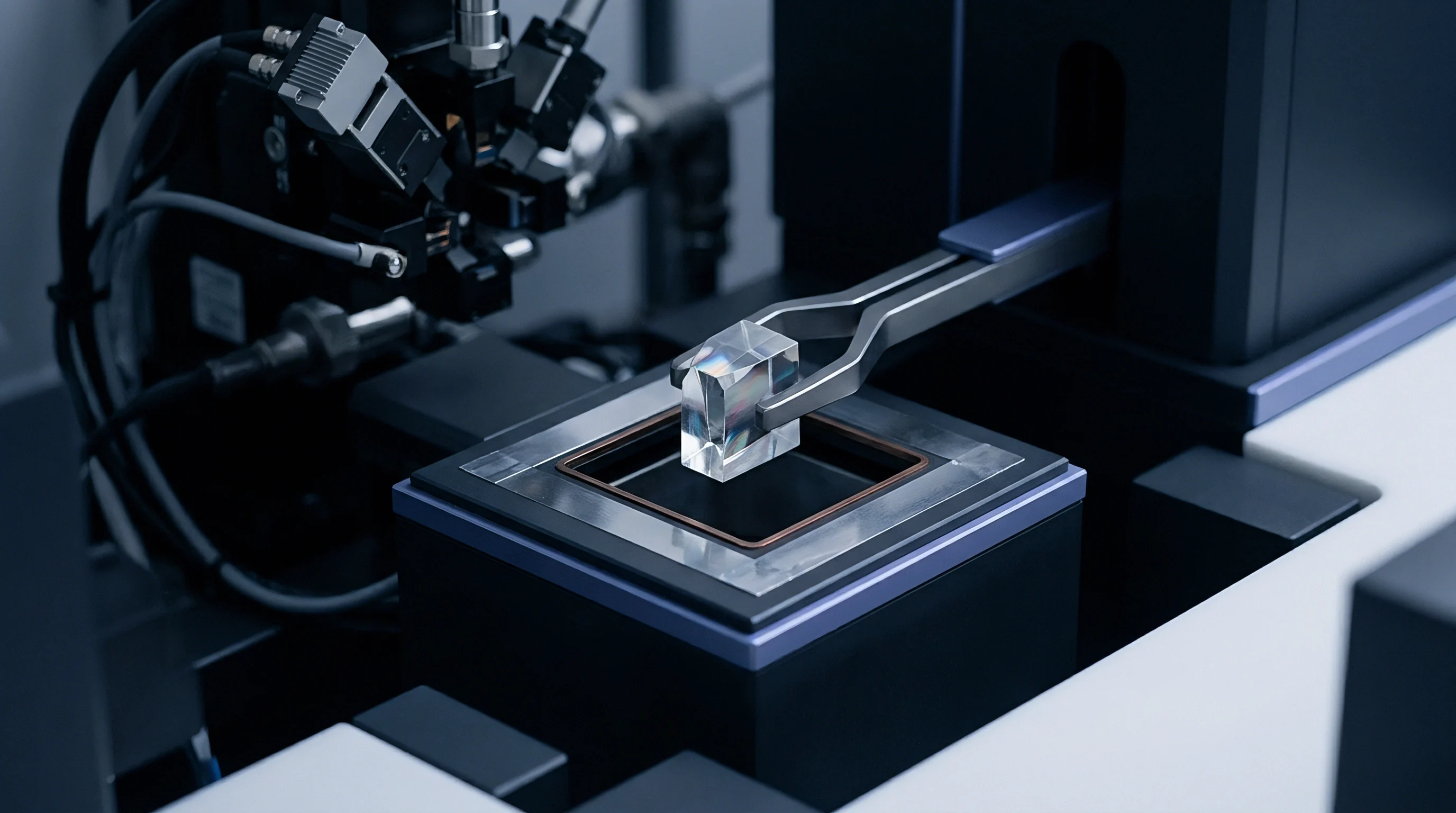

Asymptote
Tracking the rate of temperature change mathematically grounds calibration in physical stability rather than arbitrary timers. Instead of enforcing a fixed ten-minute dwell on every sensor package, data acquisition systems sample real-time bridge voltage or integrated RTD output at millisecond intervals. Once the numerical derivative of sensor output over time drops below a set slope threshold, heat transfer is low enough to proceed.
Software can then fit successive points to a decaying exponential to project the final asymptotic value before the chamber finishes its ramp.

Can Die Stresses Mimic Incomplete Equilibrium?
Mechanical strain inside silicon diaphragms relaxes on time scales that closely match thermal dissipation. In extreme thermal zones, mismatched expansion between the die, glass pedestal, and metal header generates mechanical stress, showing up as resistance shifts across piezoresistive gauges. Disentangling thermal lag from stress relaxation requires monitoring two variables at once.
By reading uncompensated bridge voltage alongside an internal diode temperature sensor, software can isolate mechanical creep from lingering thermal gradients.
| Package Architecture | Convective Medium | Thermal Time Constant (s) | Minimum 5-Tau Dwell (s) | Residual Error at 3-Tau (mK) |
|---|---|---|---|---|
| TO-8 Header Open Cavity | Fluorochemical Liquid | 1.8 | 9.0 | 14.2 |
| Ceramic SMD Gel Filled | Silicone Oil | 4.2 | 21.0 | 33.8 |
| Stainless 316L Welded Probe | Silicone Oil | 14.6 | 73.0 | 117.5 |
| Overmolded Automotive Shell | Forced Air Nitrogen | 48.0 | 240.0 | 386.4 |
| Values reflect experimental step transitions between minus 40 degrees Celsius and plus 125 degrees Celsius. | ||||
Calculating internal stabilization in real time relies on discrete routines running directly at the test socket level.
- Sample active sensing elements and internal reference diodes at 100 millisecond intervals, bounded by the signal noise floor.
- Compute moving averages over a ten-point window to block line frequency noise. Unfiltered readings invite false stability triggers.
- Calculate first and second derivatives of bridge voltage over rolling five-second windows. A non-zero second derivative signals active exponential curvature.
- Compare the rate of change against the application tolerance band. Setting thresholds above 0.005 percent span per minute causes premature cutoff.
- Verify reference bath stability over the same window with a secondary calibrated platinum thermometer. Bath drift invalidates sensor stabilization logic.
A temperature drift rate of five millikelvin per minute indicates equilibrium only when the reference bath holds two millikelvin stability over identical durations.
Stabilization ends when consecutive readings settle into true stationarity without directional drift.


Bath
Fluid agitation and spatial uniformity set the boundary layer resistance around a sensor package. Forced liquid baths deliver convective heat transfer coefficients up to two orders of magnitude above stagnant air chambers. Immersing parts in stirred liquid drops external film resistance, leaving internal conduction as the governing factor in total stabilization time.
Even so, dead zones or poor circulation in deep oil wells create local temperature gradients larger than the resolution of precision standards.

Where Does Lead Conduction Distort Chamber Dwells?
Copper wiring harnesses act like heat pipes, siphoning energy away from sensor packages toward colder terminal blocks outside the bath. Even with the sensor body immersed in an isothermal zone, heavy leads pull heat through their cross-section and depress temperature at the bond pads. The sensing element sits midway along a heat dissipation path, so it never reaches bath temperature.
Leaving the part in the bath longer does not solve the problem; the assembly simply settles into a false equilibrium offset from the fluid.
Immersion depth must equal twenty lead diameters to eliminate conduction errors along solid copper connection paths.
Verifying bath or chamber uniformity takes active profiling with multi-junction platinum probes. In air-based fixtures, high-density component trays create stagnation pockets that shelter interior parts from circulation. Sensors along the tray perimeter reach setpoint four minutes before units in the middle.
If batch processing runs without tracking individual units, test routines must extend dwell timers to cover the worst-case position, dragging down throughput across the line.
Shortening soak times to hit daily output goals bakes offset errors into finished inventory, driving up field returns when parts miss temperature accuracy specs in customer systems.

Variance
Uncertainty budgets balloon quickly when soak times are cut short of physical equilibrium. Calibration software usually models thermal response by taking voltage readings at fixed nodes ~ often minus 40, plus 25, and plus 125 degrees Celsius ~ and fitting a second-order polynomial to extract offset, gain, and cross-sensitivity terms. If a sensor retains a 1.5 degree Celsius lag during the cold measurement, the fitted curve rotates off the remaining points.
The polynomial coefficients end up modeling a transient thermal delay rather than material properties, which distorts span calibration once the sensor reaches a stable field environment.
| Stabilization Duration | Die Temperature Error at Trim | Calculated Alpha Coefficient | Calculated Beta Coefficient | Full-Scale Output Error |
|---|---|---|---|---|
| 7 Tau (Nominal) | 0.08 K | 1.0004 | minus 0.00012 | plus 0.04 percent |
| 5 Tau (Standard) | 0.67 K | 1.0028 | minus 0.00019 | plus 0.11 percent |
| 3 Tau (Truncated) | 4.98 K | 1.0215 | minus 0.00078 | plus 0.89 percent |
| 2 Tau (Accelerated) | 13.53 K | 1.0640 | minus 0.00214 | plus 2.45 percent |
High-precision calibration requires balancing capital equipment costs against yield loss from wider tolerance limits. Every extra minute spent inside an environmental chamber ties up automated test capacity. To avoid writing complex software routines, test engineers frequently assign static soak intervals tuned to the heaviest package.
That approach inflates cycle times for low-mass parts that reach equilibrium in seconds.
Dynamic detection criteria eliminate this overhead by freeing dwell durations from static timers.
- Derivative threshold verification ends dwells as soon as rate-of-change limits fall within the uncertainty budget.
- Thermal model validation compares observed die response against known package time constants.
- Reference drift screening pauses stability checks if fluid bath temperature drifts outside calibration limits.
- Hysteresis tracking detects residual mechanical strain by comparing ascending and descending calibration curves.
Longer dwells protect calibration integrity, but they consume factory output.
Metrologists still debate whether predictive exponential models can reconstruct steady-state voltages from early transient slopes without pushing calibration uncertainties past lab audit standards.

Clause
Supply contracts for compensated sensors should specify stabilization verification rules rather than relying on general calibration claims. Vendor datasheets state total error bands across wide temperature ranges, but quality audits routinely show those figures come from fitted models rather than isothermal verification at each point. If receiving protocols omit soak verification requirements, suppliers trim dwell times to boost production yields, shifting long-term drift risks onto the buyer.
Test specifications need clear, verifiable criteria for thermal equilibrium. Contracts covering calibration procedures should require suppliers to log raw rate-of-change telemetry alongside serial-number trim coefficients. If receiving audits spot shifts in temperature coefficients, reviewing that dwell telemetry reveals whether parts actually reached equilibrium before coefficients were programmed.
A purchase contract stipulating ISO 17025 accredited calibration mandates recorded proof that dwell stability criteria did not exceed expanded measurement uncertainty budgets.
Section 6.4 of ISO 17025 requires suppliers to account for every significant thermal transfer mechanism, making clear that incomplete thermal soak invalidates stated calibration uncertainties.