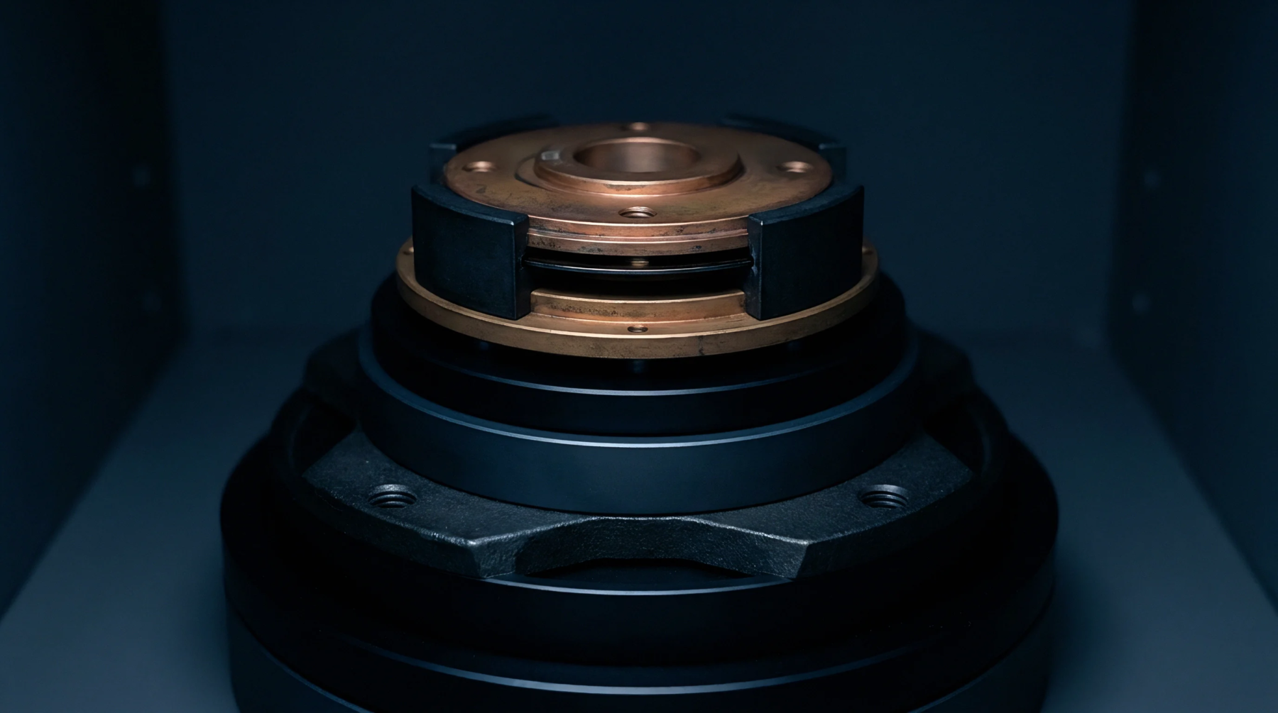
Mechanical Decoupling
Structural engineering designs use thin, compliant sections to isolate sensitive transducers from mounting stresses and thermal expansion. An isolation neck flexure reduces the transmission of unwanted clamping force and parasitic torque to the sensing element. This design maintains the accuracy of the transducer under variable mounting conditions.
High measurement sensitivity is preserved by keeping the load path aligned.
Deflection Limit
Deflection patterns of the flexure are calculated using thin beam formulas to establish the stress limits of the design. When integrating an isolation neck flexure, the material must withstand repetitive cyclic loads without fatigue or plastic deformation. The cross section is minimized to maximize mechanical resistance to thermal conduction.
Calculations must account for the spring rate to prevent resonant vibrations from altering the transducer output.
Sensory Verification
Calibration of the isolated transducer involves applying known reference loads and measuring the cross-sensitivity to mounting strain. An isolation neck flexure is evaluated by tightening the mounting bolts to different torques while monitoring the output signal. The sensor output must remain stable within the specified limits.
Test setups use precision laser interferometers to measure the physical deflection of the neck during loading. Certifying the flexure requires documenting the material hardness and the dimensional accuracy of the neck thickness.
Thermal Performance
Ambient temperature changes induce stress across the flexure if the sensor housing and mounting bracket have different expansion coefficients. High temperature gradients will generate a transient force that shifts the zero point.