Selecting Converter Sample Rates for Powerline Interference Cancellation
Select converter sample rates whose decimation zeros align with nominal mains frequencies, using crystal timing to prevent drift-induced rejection loss.


Notch
In a delta-sigma analog-to-digital converter, rejecting 50 Hz and 60 Hz powerline interference depends on placing the decimation filter’s transfer zeros directly over the line frequencies. A sinc filter calculates a running average across an integer count of mains cycles, which drives transmission attenuation toward negative infinity at exact multiples of the output data rate. When an instrumentation front-end digitizes low-level transducer outputs from strain gauges, thermocouples, or biopotential electrodes, displacement currents from nearby mains wiring induce microvolt-level hum across the source impedances.
Suppressing that hum without analog twin-T active filters requires locking the converter’s output word rate to the line period.
Setting the output data rate of a third-order sinc filter to 10 Hz yields concurrent attenuation zeros at 50 Hz, 60 Hz, and their higher harmonics. At 10 Hz, each conversion period spans 100 milliseconds ~ long enough to contain five full cycles of 50 Hz current and six full cycles of 60 Hz current. Across that window, the Dirichlet kernel falls to zero transmission at both fundamental line frequencies.
A 10 Hz conversion word rate delivers 102 dB normal-mode rejection against concurrent 50 Hz and 60 Hz interference when master clock jitter remains below 18 picoseconds RMS.
Pushing to a higher data rate breaks concurrent rejection. Systems built strictly for North American or Japanese 60 Hz utility grids run at rates like 60 Hz, 30 Hz, 20 Hz, or 15 Hz. European and Asian installations on 50 Hz power require 50 Hz, 25 Hz, 16.67 Hz, or 12.5 Hz. A rate of 16.67 Hz gives complete rejection across 50 Hz regions alongside a usable three-decibel signal passband of roughly 4.3 Hz; 20 Hz serves 60 Hz grids with a 5.2 Hz passband.

Mathematical Mechanics of Decimation Transfer Functions
The continuous-time frequency response of a digital sinc filter with order K and decimation ratio M relative to the modulator sampling frequency exhibits periodic transmission dips described by trigonometric ratios.
H(f) = ( sin(pi f M / f_MOD) / ( M sin(pi f / f_MOD) ) )^K
Zeros occur at every integer multiple of f_MOD / M, which equals the converter output data rate f_DATA. When f_DATA is 50 Hz, zeros align with 50 Hz, 100 Hz, 150 Hz, and 200 Hz. Third-order filters produce deep local notches, but the attenuation trough is narrow. As utility grid frequency wanders away from nominal, rejection degrades at a rate set by the filter order and the size of the displacement.
Settling time limits throughput. A sinc3 filter requires three full conversion cycles before an output word reflects a full-scale step input at the analog terminal; a sinc4 filter requires four. A multiplexed architecture cycling across eight differential thermocouple channels cannot hold a 10 Hz per-channel rate without pulling total system sampling down to 1.25 Hz. Switching the multiplexer forces the filter to flush its internal taps, discarding two to three conversion cycles while the pipeline refills.
Choosing the wrong sampling rate pushes the burden downstream, forcing digital signal processors to execute heavy notch filtering that adds phase distortion and burns clock cycles.

Drift
Power distribution grids never hold a completely fixed frequency. Regional balancing authorities continuously adjust turbine generation against industrial load, so grid frequency drifts through the daily cycle. Under standard dispatch rules, these variations stay within bounded limits, but even small departures pull the line frequency off the converter’s notch.
International standard IEC 61000-4-30 defines Class A measurement criteria for power quality instruments, establishing permissible frequency deviations across interconnected networks. European continental interconnects hold nominal 50 Hz within a standard band of 49.5 Hz to 50.5 Hz during non-emergency operation. North American interconnections maintain 60 Hz within a normal window of 59.95 Hz to 60.05 Hz, though severe generation loss events permit brief excursions between 59.5 Hz and 60.5 Hz. Isolated or islanded grids display broader swings, occasionally hitting two hertz off nominal.

Attenuation Loss across Grid Tolerance Windows
A delta-sigma converter clocked from a fixed reference places its zero at an ideal 50.00 Hz. When the mains supply shifts to 50.50 Hz, the interference tone climbs up the steep rejection skirt. Normal-mode rejection drops from theoretical values above 120 dB down to practical readings between 35 dB and 48 dB.
| Filter Configuration | Output Data Rate | Rejection at 50.00 Hz | Rejection at 50.25 Hz | Rejection at 50.50 Hz | Rejection at 51.00 Hz |
|---|---|---|---|---|---|
| Sinc1 (Running Average) | 50.0 Hz | 98.4 dB | 42.1 dB | 36.1 dB | 30.1 dB |
| Sinc3 Decimation | 50.0 Hz | 124.0 dB | 58.2 dB | 46.3 dB | 34.4 dB |
| Sinc4 Decimation | 50.0 Hz | 136.5 dB | 68.4 dB | 52.7 dB | 38.2 dB |
| Sinc3 (Dual 50/60 Mode) | 10.0 Hz | 118.2 dB | 64.5 dB | 54.1 dB | 41.8 dB |
| Modified Sinc4 + Averaging | 16.67 Hz | 121.7 dB | 71.3 dB | 59.8 dB | 46.2 dB |
Higher-order filters hold up better at fractional grid offsets than first-order filters. Their steeper rejection slopes sustain higher baseline suppression across the full IEC 61000-4-30 Class A operating margin.
On-chip clock tolerances compound the error. Integrated relaxation oscillators often show factory calibration tolerances of plus or minus two percent across the commercial temperature range. An internal oscillator running two percent fast pushes a 50.00 Hz notch out to 51.00 Hz, decoupling the zero from the utility line.
Normal-mode rejection falls below 35 dB before the grid frequency moves at all.
A clock drift exceeding 0.75 percent strips standard third-order sinc decimation filters of half their nominal decibel attenuation.
Tracking the line period in real time avoids this mismatch. Some precision converters integrate digital phase-locked loops that take an external square wave derived from an optoisolator on the mains supply. The modulator then trims its division ratio dynamically, steering the filter zeros onto the instantaneous line frequency.
However, optoisolation circuitry adds board area that compact enclosures cannot always spare.
Fold
Nyquist architectures treat out-of-band powerline harmonics differently than delta-sigma decimation stages do. Successive approximation register converters sample an input during a brief track-and-hold window. Without an analog anti-aliasing filter with steep transition bands, any interference above half the sampling rate folds straight back into the baseband.
Powerline harmonics regularly extend into the kilohertz range. Switched-mode power supplies, variable-frequency drives, and electronic ballasts draw non-sinusoidal currents that inject high distortion into industrial distribution feeds. Triplen harmonics at 150 Hz, 250 Hz, 350 Hz, 450 Hz, 550 Hz, and 650 Hz routinely reach several percent of fundamental line voltage.
Total harmonic distortion in industrial environments often clears eight percent.
Alias Mapping Arithmetic in Direct Sampling
When a SAR converter digitizes an analog signal at sample rate f_S, an unwanted interference component at frequency f_IN folds to an apparent digital baseband frequency f_ALIAS determined by modular arithmetic.
f_ALIAS = | f_IN – m f_S |
The integer m represents the harmonic zone index that minimizes the difference. A SAR converter operating at a sample rate of 120 Hz to observe a slow physiological signal converts 60 Hz fundamental hum to an apparent frequency of 60 Hz. A fifth harmonic at 300 Hz folds back to 60 Hz because 300 minus two times 120 equals 60. A seventh harmonic at 420 Hz folds to 60 Hz because 420 minus three times 120 equals 60.
All odd harmonics superimpose directly on top of the digitized 60 Hz fundamental tone.
- Alias Zone Overlap occurs when distinct high-frequency spectral lines collapse into identical lower-frequency bins, preventing digital separation in subsequent software filters.
- Analog Filter Inflation results from steep roll-off requirements in low-order front-end active filters, swelling component count and drifting resistor tolerances over operating temperature.
- Phase Distortion Penalty accumulates when passive RC stages introduce group delay variations that corrupt transient sensor responses near the filter corner frequency.
- Noise Floor Folding transpires when broad-spectrum powerline pickup outside the Nyquist band folds multiple times, raising the total in-band RMS noise floor.
Sample rate selection directly dictates the required complexity of the physical input filter. If the sample rate aligns line harmonics with zero-frequency alias points, steady-state hum turns into an uncalibrated DC offset. Sampling at exactly 50 Hz aliases a 50 Hz tone to zero hertz, and a 100 Hz second harmonic aliases to zero hertz as well.
Every harmonic folds into a static error that shifts baseline sensor calibration.
Sampling mains interference at exact integer multiples of line frequency converts dynamic alternating ripple into static measurement offset error.
An anti-aliasing filter before a SAR converter must maintain significant attenuation by f_S minus f_MAX, where f_MAX is the required signal bandwidth. High-order active filters require board area, add resistor thermal noise, and introduce op-amp offset drift. Oversampled delta-sigma converters avoid most of this overhead by sampling at megahertz rates, shifting the required analog corner far enough out that a simple single-pole RC filter is sufficient.
Low-order RC front ends preserve clean step responses when sampling frequencies sit far above line harmonics.

Quartz
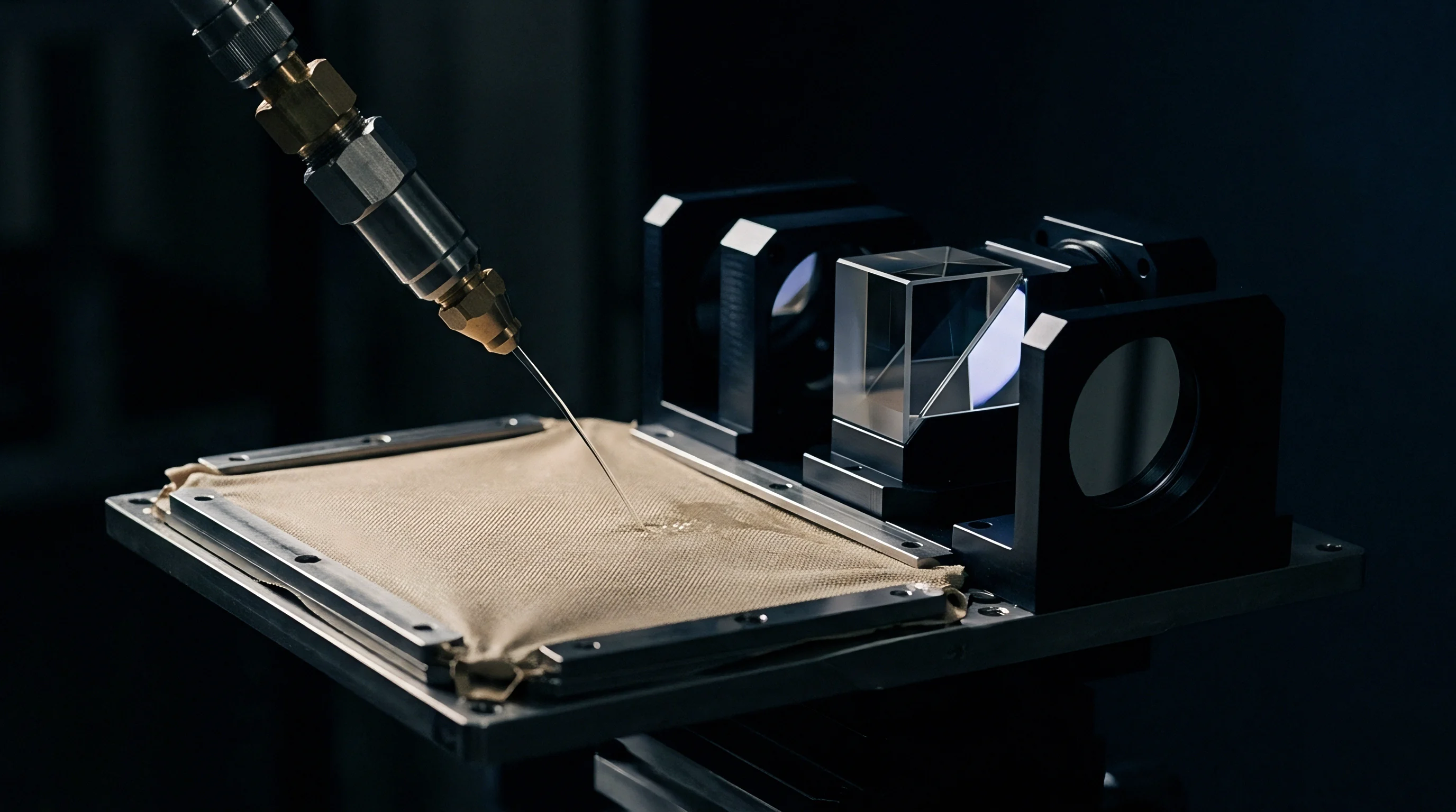
Holding stable rejection notches across operating temperatures requires a dedicated timing source. Silicon relaxation oscillators integrated on converter dies drift with temperature, age, and supply variations ~ effects large enough to pull the narrow decimation zero off frequency. High-precision designs therefore rely on quartz crystals or temperature-compensated crystal oscillators to stabilize filter timing.
Typical converter datasheets specify integrated clock tolerances of plus or minus 2.5 percent from minus forty to plus one hundred twenty-five degrees Celsius. Over a modest five-degree temperature swing, an internal RC oscillator drifts between 150 and 300 parts per million. That shift nudges the filter zero away from the line frequency by dozens of millihertz, costing ten to twenty decibels of rejection.

Comparative Performance of Converter Clock Architectures
Selecting an external timing device dictates the sustained depth of interference attenuation. The table contrasts common timing references evaluated under industrial instrumentation conditions.
| Timing Device Modality | Initial Tolerance | Thermal Drift (-40C to +85C) | Aging per Year | Sustained Rejection at 50 Hz |
|---|---|---|---|---|
| Internal RC Oscillator | ±1.5% | ±2.0% | ±0.5% | 38 dB |
| Ceramic Resonator | ±0.5% | ±0.3% | ±0.1% | 52 dB |
| Standard AT-Cut Quartz Crystal | ±10 ppm | ±30 ppm | ±3 ppm | 88 dB |
| Temperature-Compensated Crystal (TCXO) | ±1.0 ppm | ±2.5 ppm | ±1 ppm | 106 dB |
| Mains-Synchronous Digital PLL | ±0.05% | Tracks Grid | None | 112 dB |
AT-cut quartz crystals with temperature stabilities within 30 parts per million maintain filter notch placement with minimal degradation. At that point, the limiting factor becomes the stability of the grid itself: if the line shifts by 0.2 Hz, an atomic reference on the board cannot keep the notch aligned with the interference.
Hum breakthrough is frequently attributed to board layout or missing ground shields. Phase noise on the modulator clock plays a minor role in high-resolution converters, though it primarily lowers effective number of bits rather than moving the notch. In field transmitters, the main cause of degraded line rejection remains the temperature coefficient of uncompensated oscillator circuits.
Published notch depths of 120 dB assume an external crystal reference operating under laboratory conditions.


Procurement
The chosen converter sample rate largely dictates silicon architecture, setting bill of materials costs and restricting second-source availability. Precision delta-sigma converters with simultaneous 50/60 Hz rejection come from a small group of analog manufacturers. When a specification demands 100 dB rejection at both 50 Hz and 60 Hz at a 10 Hz word rate, procurement narrows to specific part families that integrate programmable sinc filters and programmable gain amplifiers.
High-resolution delta-sigma parts running at low sample rates are readily available in sample quantities, but volume production runs face long lead times when multi-channel simultaneous sampling is required. Choosing multi-channel SAR converters with external digital filtering running on the host microcontroller opens sourcing to dozens of pin-compatible options across multiple fabs.

Modality Trade-Offs in Industrial Converters
Balancing acquisition hardware expenses requires evaluating peripheral component burdens alongside converter unit prices. The following criteria govern procurement audits for noise-sensitive sensing channels.
- Converter Silicon Modality governs whether anti-aliasing burdens fall on discrete analog active filters or integrated digital decimation pipelines. Delta-sigma architectures eliminate multi-pole operational amplifier circuits while consuming higher baseline conversion power.
- Clock Source Cost Overhead demands budget allocation for an external crystal and loading capacitors when internal oscillators fail to hold required notch bandwidths. High-stability crystals add bill of materials expense that budget-constrained IoT monitors cannot absorb.
- Channel Expansion Density determines package footprint and routing layout complexity on high-density input modules. Simultaneous sampling delta-sigma parts carry higher per-channel price points than multiplexed SAR solutions.
- Multi-Sourcing Pin Compatibility limits vulnerability during wafer fab allocation cycles. Highly specialized analog converters featuring proprietary decimation filters rarely possess direct pin-compatible drop-in alternatives from competing suppliers.
Cross-qualifying second sources often fails on digital filter behavior. Two 24-bit delta-sigma converters may share a pinout and an SPI register map, but their internal decimation ratios and master clock division schemes rarely match. A device requiring a 4.9152 MHz crystal for a 10 Hz output word cannot drop into a layout configured for 4.096 MHz without shifting the filter zeros off the powerline frequency.
The standard procurement specification under IEC 60770-1 mandates that intelligent industrial transmitters document static and dynamic measurement accuracy across supply and ambient extremes, explicitly binding warranty validation to defined line-frequency rejection tolerances.